83062165_201508
Information regarding the system hydraulics
All details are recommendations and may vary from system to system. The expansion vessel sizes stated are valid for a static
head of up to 10 metres only.
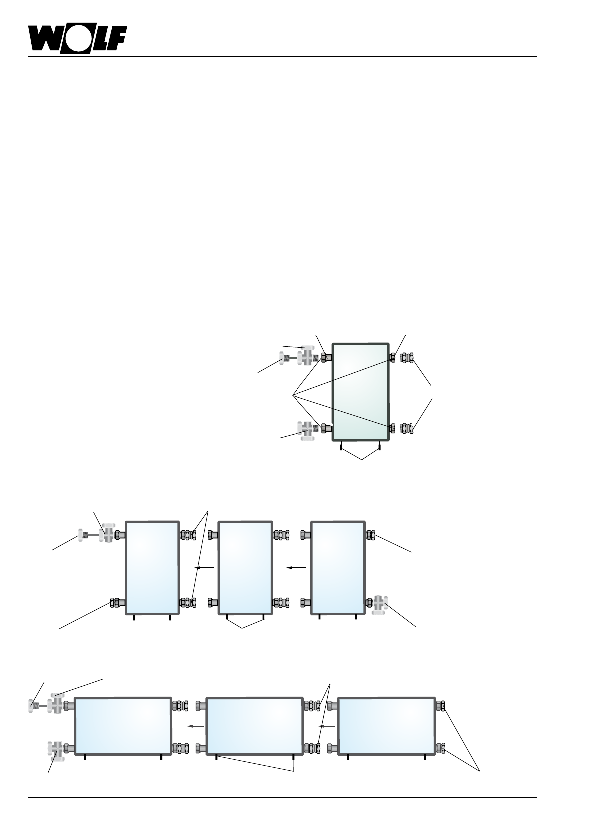
Information regarding
the system hydraulics
• Thecollectorscanbeoperatedwithahigh specic owrate(so-called
High-Flow).Advantages:Thecollectoriswellcooled=highcollectorefciency
level,lowheatlossesattheowline.Disadvantages:Highpressuredrop
= powerful pump, large pipe cross-sections.
• The collectors can be operated with a low specic ow rate (so-called
Low-Flow). Here, the advantages and disadvantages are reversed compared
totheHigh-Flowoperation.Anadditionaladvantage,duetothehigherow
temperature,istheeffectiveoperationofastraticationcylinder.
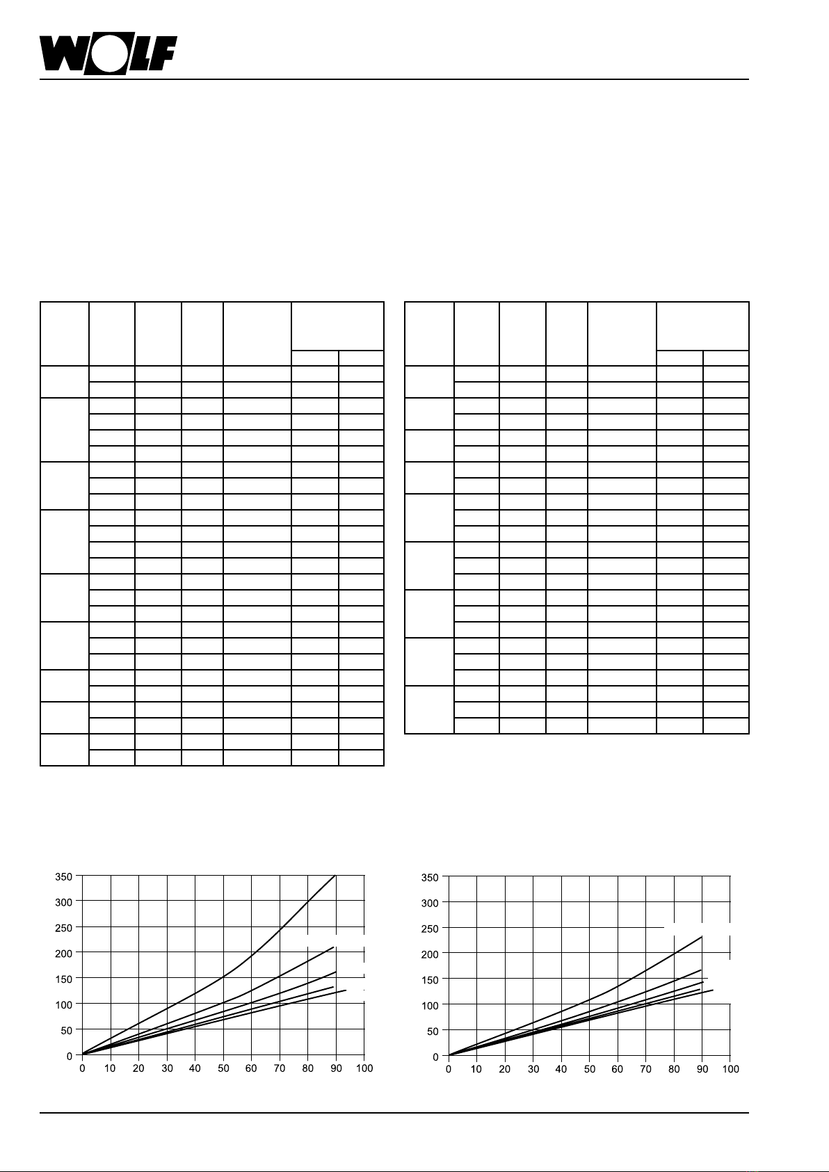
Flow data: High-Flow (90 l/h x coll), ANRO 30 °C Flow data: Low-Flow (50 l/h x coll), ANRO 30 °C
Collector
number
Solar
line
length
(m)
Solar
pipe Ø
(mm)
Pump
group
DHW
cylinder
Expansion vessel
2.5 bar
F3-1 F3-Q
2
2
15 15 x 1 10 SEM-2-300 18 18
30 18 x 1 10 SEM-2-300 18 18
3
3
3
3
10 15 x 1 10 SEM-2-400 25 35
20 18 x 1 10 SEM-2-400 35 35
30 15 x 1 20 SEM-2-400 25 35
70 18 x 1 20 SEM-2-400 35 35
4
4
4
15 18 x 1 10 SEM-1-500 35 50
30 22 x 1 10 SEM-1-500 50 50
50 18 x 1 20 SEM-1-500 35 50
5
5
5
5
10 18 x 1 10 SEM-1-750 50 50
20 22 x 1 10 SEM-1-750 50 50
35 18 x 1 20 SEM-1-750 50 50
90 22 x 1 20 SEM-1-750 50 50
6
6
6
15 22 x 1 10 SEM-1-750 80 80
30 18 x 1 20 SEM-1-750 50 80
70 18 x 1 20 SEM-1-750 50 80
7
7
7
15 28 x 1.5 10 SEM-1-1000 80 80
15 18 x 1 20 SEM-1-1000 80 80
50 22 x 1 20 SEM-1-1000 80 80
8
8
50 22 x 1 20 SEM-1-1000 80 80
100 28 x 1.5 20 SEM-1-1000 80 105
9
9
20 22 x 1 20 SEM-1-1000 80 80
80 28 x 1.5 20 SEM-1-1000 80 105
10
10
10 22 x 1 20 SEM-1-1000 80 105
50 28 x 1.5 20 SEM-1-1000 105 105
Collector
number
Solar
line
length
(m)
Solar
pipe Ø
(mm)
Pump
group
DHW
cylinder
Expansion vessel
2.5 bar
F3-1 F3-Q
2
2
20 12 x 1 10 SEM-2-300 18 18
50 15 x 1 10 SEM-2-300 18 18
3
3
35 15 x 1 10 SEM-2-400 25 35
80 18 x 1 10 SEM-2-400 35 35
4
4
25 15 x 1 10 SEM-1-500 35 35
50 18 x 1 10 SEM-2-400 35 50
5
5
20 15 x 1 10 SEM-1-500 50 50
45 18 x 1 10 SEM-1-750 50 50
6
6
6
15 15 x 1 10 SEM-1-750 50 80
30 15 x 1 20 SEM-1-750 50 80
35 18 x 1 10 SEM-1-750 50 80
7
7
7
30 18 x 1 10 SEM-1-1000 80 80
30 15 x 1 20 SEM-1-1000 80 80
60 18 x 1 20 SEM-1-1000 80 80
8
8
8
25 18 x 1 10 SEM-1-1000 80 80
25 15 x 1 20 SEM-1-1000 80 80
50 18 x 1 20 SEM-1-1000 80 80
9
9
9
20 18 x 1 10 SEM-1-1000 80 80
50 22 x 1 10 SEM-1-1000 80 80
50 18 x 1 20 SEM-1-1000 80 80
10
10
10
15 18 x 1 10 SEM-1-1000 80 80
40 18 x 1 10 SEM-1-1000 80 105
40 22 x 1 10 SEM-1-1000 80 105
1 coll. 1 coll.
3 coll. 3 coll.
5 coll. 5 coll.
7 collectors
7 coll.
10 collectors
10 collectors
Pressure drop, F3-1Q, F3-Q with ANRO 30 °C Pressure drop, F3-1 with ANRO 30 °C
Flow rate per collector (l/h) Flow rate per collector (l/h)
Pressure drop, entire array (mbar)
Pressure drop, entire array (mbar)