Solahart SE3000H User manual

Battery System Quick Start Guide
Battery System: SolarEdge Energy Bank and SolarEdge Energy
Hub Series Inverter
System Overview Diagram
Note:Installation of the PV system is not within the scope of this document.
Warnings
Disclaimer of Liability and Warranty: This pictorial guide does not replace installation manuals supplied
with the components. Solahart assumes no responsibility for loss, damage or expense resulting from
improper installation, handling or misuse of components. Refer to the warranty statement in the Solahart
Owner’s guide for full warranty terms and conditions.
Installer Responsibilities
The installer is solely responsible for:
•Observing and conforming to all relevant Australian Standards, all relevant Clean Energy Council
Accreditation guidelines and all applicable laws, ordinances, regulations, codes of practice and local
or national building codes, including any that may have superseded this guide.
•Ensuring that the installation complies with AS/NZS 3000, AS/NZS 5139, AS/NZS 5033, AS 4777.1,
AS/NZS 1768, and any relevant electrical service and installation rules for the state or territory where
the system is installed.
•Ensuring that the Battery system and associated components are appropriate for the particular
installation and the installation environment.
2
•Ensuring only parts supplied by Solahart Industries and installer supplied parts as specified by
Solahart Industries are utilised (substitution of parts may void the warranty and invalidate certification).
•Ensuring that mounting fasteners have adequate pull-out strength and shear capacities to suit the
installation.
•Ensuring safe installation of all electrical aspects of the Battery system.
•Ensuring that the building and building structures can withstand the additional loads and forces
generated as a result of installing the Battery system.
•Ensuring mounting clearance requirements for all components are maintained.
•Ensuring components are not exposed to direct sunlight, rain fall and snow accumulation.
•Ensuring that the batteries and their components are protected from damage during transportation
and storage.
•Ensuring that the weight of the battery is taken into account when handling and that all WHS policies
are followed.
•Ensuring the Battery is connected to an approved SolarEdge Inverter and the SolarEdge Monitoring
Platform (via an internet connection).
Tools Required
•Drill and drill bits suitable for drilling holes in the desired mounting surface/structure.
•M5 tools.
•Torque wrench.
•Spirit level.
•Adjustable spanner.
•Electricians hand tools (screwdrivers, pliers, side cutters, cable crimps etc.)
•DC cable 600V insulated
•Dolly with lift and ratchet straps
•An Android or IOS smart device.
Note: The SolarEdge Inverters SetApp mobile App must be downloaded before commissioning.
Note: See each component installation guides for additional tools required for installation.
Planning the Installation
Installation environment
•The battery is floor/wall mounted as per the instructions provided in this guide.
•The operating temperature (charge / discharge) for the battery is -10~50℃.
•Avoid exposing the equipment to direct sunlight or rain.
•Install the equipment away from heat/cold source where the temperature can vary significantly.
•Battery may cause interference with radio/TV interference if not installed correctly.
•Keep children / pets away from the equipment.
•Do not install the equipment in places prone to accumulate water.
•Do not put inflammable or explosive matters near the equipment.
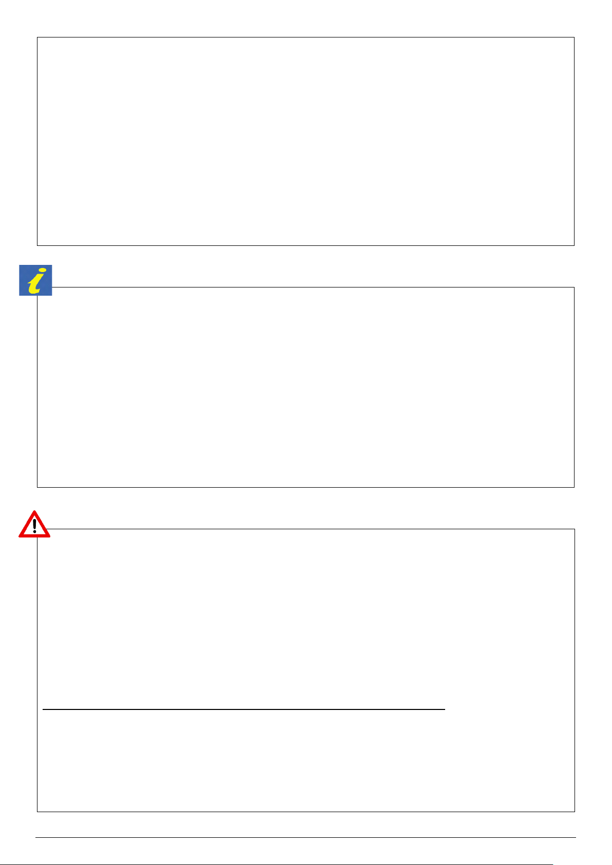
Mounting space requirements
For the SolarEdge Home Battery (High Voltage) for use with SolarEdge inverters
Floor and wall mounting space requirements:
3
20cm spacing around the battery and max 50m away from the inverter.
Note: The Installation location of the Battery must also comply with the requirements of AS/NZS 5139.
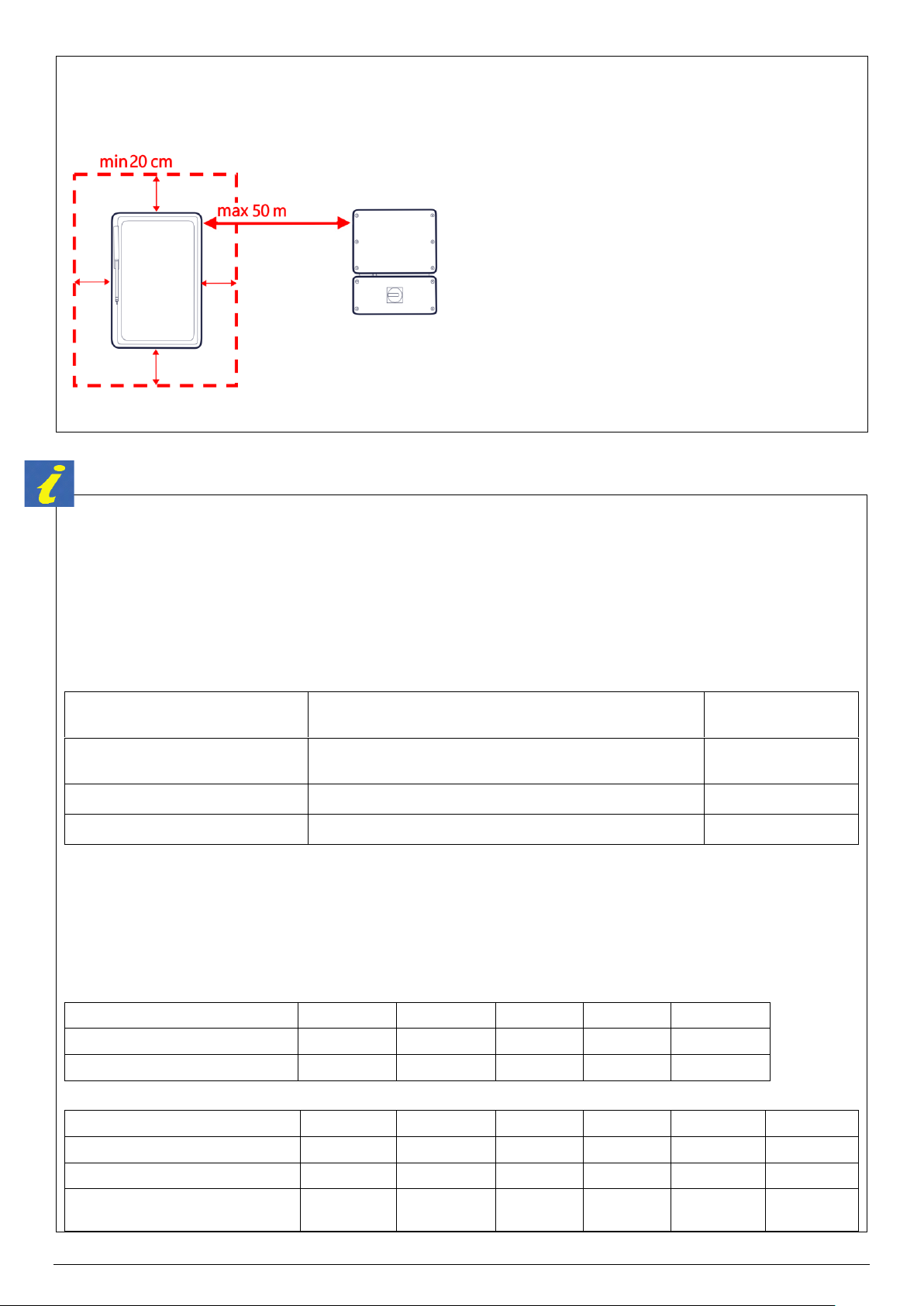
Cabling and Conduits
Any earthing cable, AC cable and conduits are not supplied by Solahart and should be selected based on
the following criteria.
Inverter DC/AC cabling must be sized and installed in accordance with AS/NZS 3000, AS/NZS 3008.1.1
and any local applicable codes.
The Battery contains an in-built 25A circuit breaker.
DC CABLE SIZING
Cable description
Cable type
Minimum Conductor
Size
Low Voltage (LV) Battery to Battery
and DC Combiner
Pair, double-insulated DC cables, 90 deg. rated
4 mm2
DC combiner to Inverter
Pair, double-insulated DC cables, 90 deg. rated
4 mm2
Battery earthing (PE)
Earthing cable complying with requirements of AS/NZS 3000
4 mm2
Note: Each 4mm2DC cable must be located in accordance with AS/NZS 3008.1.1 to achieve a current
carrying capacity of >25A (in-built battery circuit breaker).
INVERTER CABLING
Cables from the inverter(s) must be selected so that the current carrying capacity is suitable for the
maximum continuous current as shown below:
Inverter Model - Genesis
SE3000H
SE5000H
SE6000H
SE8250H
SE10000H
Maximum Input Current (Adc)
9 A
13.5 A
16.5 A
20.5 A
25.5 A
Maximum Cont. Output Current
14 A
23 A
27.5 A
37.5 A
45.5 A
Inverter Model –Energy Hub
SE3000H
SE4000H
SE5000H
SE6000H
SE8250H
SE10000H
Maximum Input Current (Adc)
8.5 A
11 A
14 A
16.5 A
22.5 A
25.5 A
Maximum Cont. Output Current
14 A
18.5 A
23 A
27.5 A
37.5 A
45.5 A
Maximum Cont. Output Current
(Back Up Operation)
14 A
18.5 A
23 A
27.5 A
34 A
41.5 A
4
Note: Rated current in backup operation are valid for installations with multiple inverters. For a single
backup inverter operation, rated current in backup is 90% of the stated value
COMMUNICATION CABLING
Cable Description
Cable Type
Cable between Inverter and Meter
CAT6
Cable between Meter and CT
CAT6
Cable between Inverter and
between each connected battery
CAT6
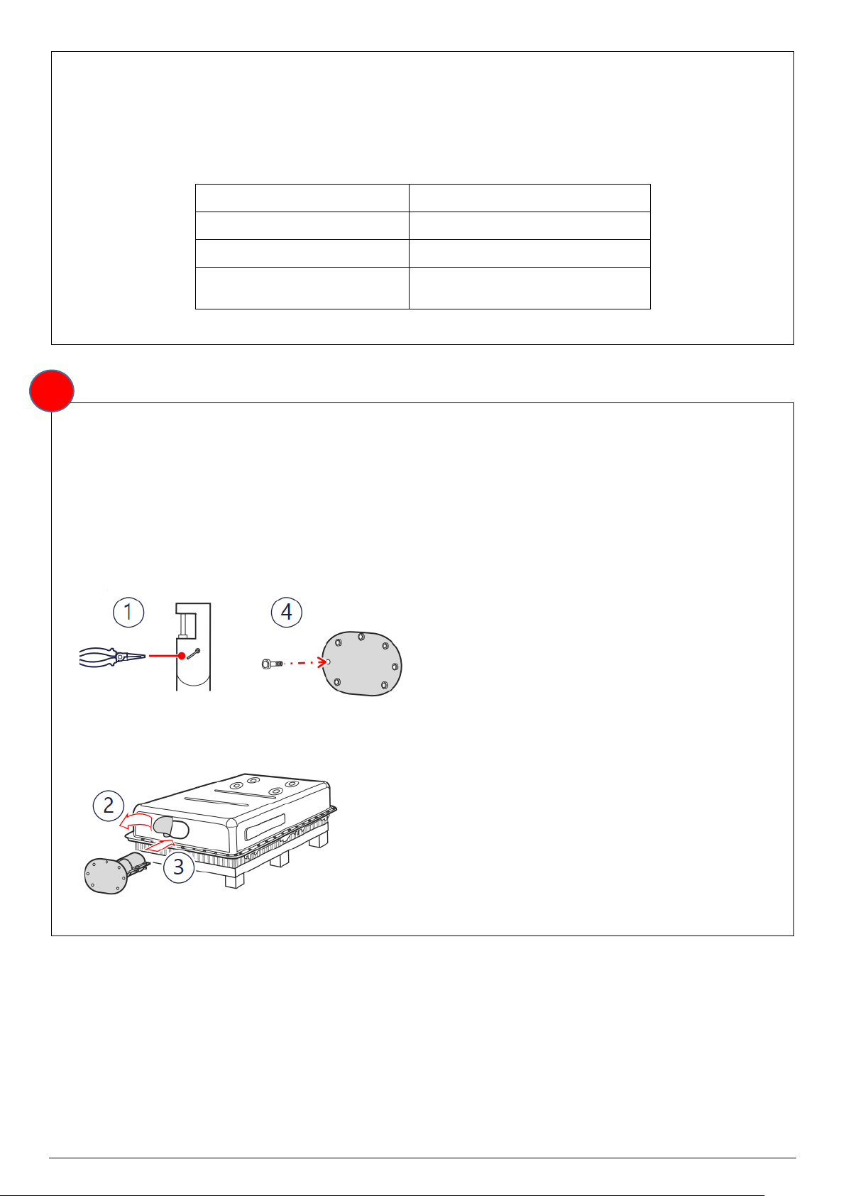
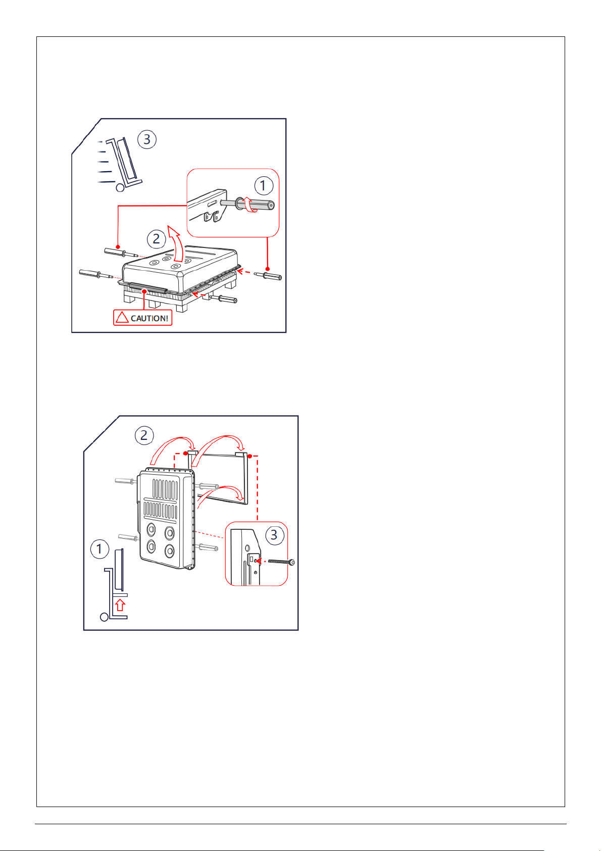
Install the fire extinguisher
Refer to the SolarEdge Home Battery Fire Extinguisher Installation Guide for further information.
1. Use long-nose pliers to straighten and remove the safety pin.
2. Remove the sticker that covers the fire extinguisher’s service hole.
3. Carefully insert the fire extinguisher into the service hole.
4. Secure the fire extinguisher with seven Allen screws (supplied). Apply a torque of 4.5N*m.
1
5
Unpacking and Mounting Battery
Refer to SolarEdge Home Battery User Manual for further mounting instructions.
Unpack contents from the SolarEdge battery packaging as per instruction
Warning: Battery modules are heavy (approximately 121 kg each). It is recommended that the
installation is done by two people.
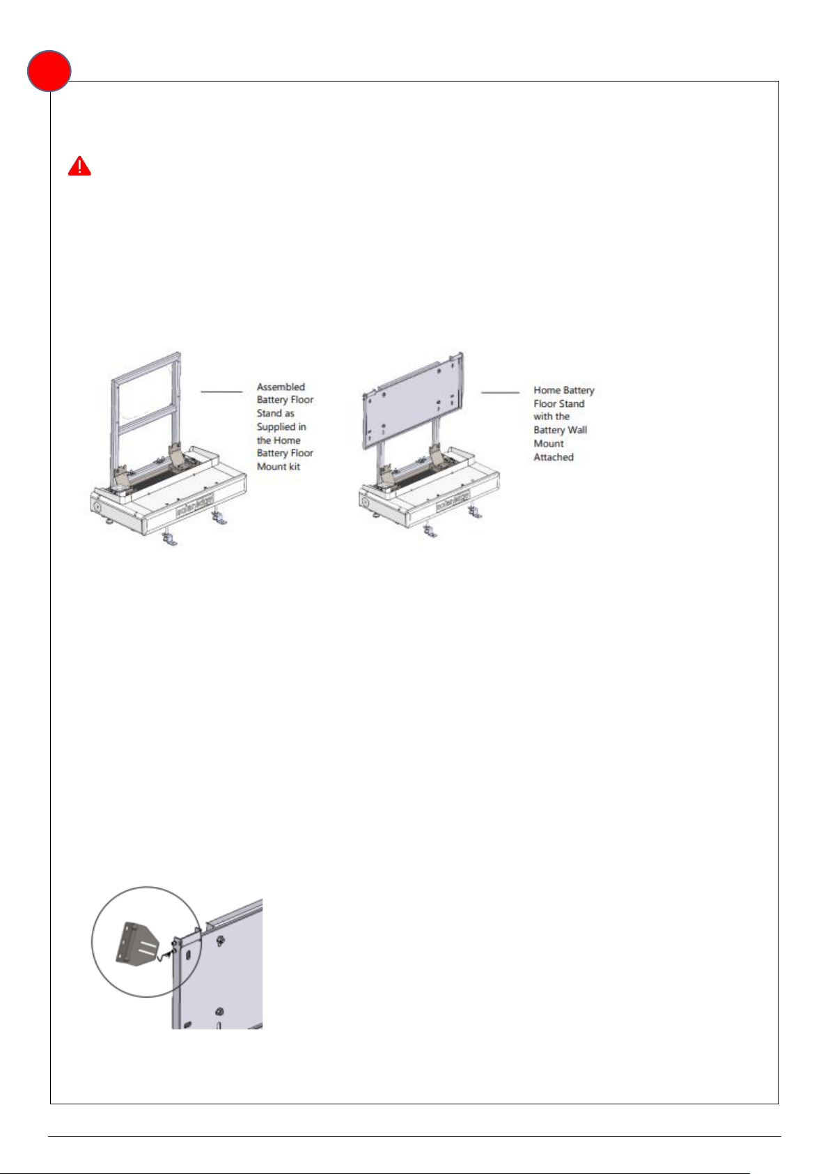
Floor mounting:
Parts for the Floor Stand Base Mount and Back Holder are supplied as part of the SolarEdge Home
Battery Floor Mount kit
The assembled floor stand includes the base and back holder as illustrated on the left in the Figure
below. The right part of the figure shows the Battery Wall Mount after being attached to the assembled
floor mount stand.
1. Unpackage the SolarEdge Home Battery Floor Mount Stand kit and arrange the parts so you can check
the parts against the parts list.
2. Move and position the floor mount base close to but not against the wall to which it will be secured.
Position the base so that the front of the base is parallel to and facing away from the wall.
3. Level and set the height of the base mount using a 5mm Allen key to turn the leg height adjustment
screws for each of floor mount base legs.
4. Hold the back holder so that the six studs are facing toward you and the connecting strut with four holes
is at the bottom.
5. Lower the back holder over the four connecting studs located at the rear of the base. As you do this,
the two lower studs on the Back Holder must sit in the outer slots of the Back Holder Securing Bracket.
6. Loosely screw the M8 nuts onto each of the back holder and base studs to hold the back holder in
place. Fully tighten at 17Nm to finally secure the back holder.
7. Hold the wall mount, front facing you, and position the mount on the securing studs of the back-holder’s
battery mounting bracket.
8. Loosely screw an M8 nut onto each of the four back holder studs to hold the wall mount in place and
then fully tighten at 17Nm to finally secure the wall mount as shown in Figure 4.
9. Use the M5 short screw to attach the lower slot of the wall bracket to each side of the wall mount and
then position the Floor Mount against the wall
10. Use the holes in the wall bracket to mark the position on the wall for three attachment holes on each
side. Move the Floor Mount aside to allow access to drill. Drill the holes, reposition the Floor Mount and
attach the wall brackets to the wall
2

6
11. (Optional) Insert a floor connector bracket between the bracket securing nut and the foot of each leg.
Position the floor connector bracket and mark a drilling hole. Remove the bracket and drill the floor
attachment holes.
12. Position and hang the battery on the wall mount.
13. Check that the battery is turned off.
14. Open the wiring gutter on the left side of the floor mount base and lay the wires in place. Pass the
cables through the wiring sleeve on the top left side of the floor mount base and connect to the battery.
If installing more than one battery per inverter, use branch connectors.
15. Insert and loosely tighten the long M5 wall bracket securing screw in the upper wall bracket slot on
each side. The long securing screw threads through the battery housing and acts a safety suspension
pin.
16. Recheck that the stand is level and if necessary fine tune the height of the legs until the stand is level.
17. In case the floor stand is being optionally fastened to the floor, replace the floor connector brackets,
and position them over the drilled hole. Secure to the floor at 17Nm and then tighten the M10 bracket
securing nuts on each leg also at 17Nm.
18. Tighten the two Wall Bracket screws M5 on each wall bracket at 17Nm.
19. Assemble the decorative cover
Note: Refer to the manufacturer’s intallation guide for details on mounting multiple batteries.
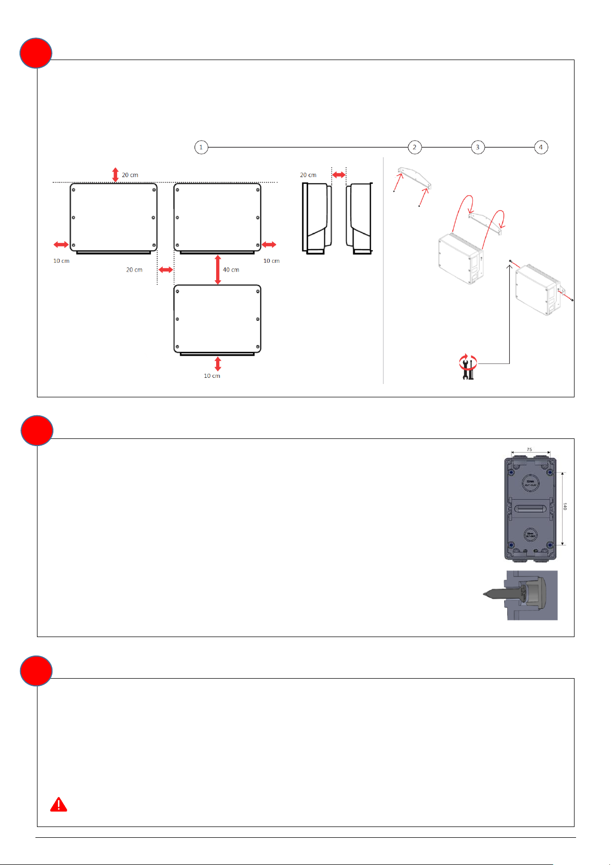
Wall mounting:
Install mounting bracket
When selecting the installation location:
• Maintain a clearance of min 20 cm from other objects.
• Make sure the max distance from the inverter is max 50 m
Warning: Make sure the installation surface sustains the weight of the battery (121kg).
1. Level the bracket.
2. Mark two drilling spots. Use either the inner or outer pair of holes. If necessary, you can use the
additional holes to secure the bracket.
3. Drill holes in the installation surface.
4. Install the mounting bracket and secure with screws.
7
Transport battery
1. Screw in all FOUR handles to the battery frame. Make sure to screw in the handles all the way.
2. Place the battery upright on a dolly and secure it with straps. Stand the battery on the rubber
protector only!
3. Transport the battery to the installation location.
Hang battery on mounting bracket
1. Lift the battery to the height of the mounting bracket.
2. Hang the battery on the mounting bracket, while holding it by the handles.
3. Secure with a mounting bracket screw (supplied) on each side. Apply a torque of 4.7Nm.
Note: The battery shall be installed and mechanically protected according to CEC Battery Installation
Guidelines and AS/NZS 5139. This includes:
•Providing restricted access to the battery system designed to prevent access by unauthorised
persons.
•Where subject to potential physical damage, mechanical protection shall be providedto the battery
system to minimise the risk of such, resulting in electrolyte leakage, including:
oCrushing
oImpact
oPuncturing
•Mechanical protection may be achieved via the use of a suitable battery system enclosure and/ or
bollards.
8
Mounting the Inverter
Follow the relevant User Manual to choose a suitable location and correctly mount the Inverter to the wall
using appropriate fasteners and with regards to clearance requirements. Diagram of the SolarEdge
Genesis inverter mounting below.
Mounting AC Isolator Enclosure(s)
ISOLATOR ENCLOSURES
1. Determine the mounting locations of the enclosures with regard to system clearances,
layout specifications and AS/NZS 3000.
2. Install a minimum of two (2) fasteners diagonally opposite, to fix the enclosure to the
wall.
3. Install the silicone rubber plugs supplied with the enclosure on the internal mounting
points.
Note: Where the Inverter is not adjacent to the switchboard to which it is connected,
an “Inverter AC Isolator” must be installed at the Inverter in accordance with
AS/NZS 3000.
Connecting DC and Communication Cables
For setting up communication between the battery and the inverter, SolarEdge strongly recommends using
SolarEdge Energy Net. If for some reason SolarEdge Energy Net cannot be used, you can set up
communication using an RS485 port
Use the following cable types:
DC - 10 AWG (10-12 AWG), 600V insulated.
Communication - 24 AWG (16-24 AWG), 600V insulated or CAT6
Warning: Carefully read all handling and safety instructions in the installation guides that come
with the battery and the inverter.
4
3
5
9
Warning: Before connecting the battery to the inverter, power off the battery.
Note: Check the communication cables to ensure the insulation is rated for the highest voltage present
inside the switchboard. Additional insulation may be required.
Note: If extension of communication cable is required, a female RJ45 joiner may be used to avoid crimping
the connector.
Warning: If extension of communication cable is required, ensure cable joints are adequately
protected from moisture.
Warning: Ensure all communication cables are adequately protected against mechanical
damage.
DC and AC Cable Wiring
Warning: Ensure all DC and AC cables are adequately protected against vermin and other
damage.
Warning: Ensure in-built DC isolator is switched OFF prior to wiring.
Note: Ensure the conductors on all cable ends are consolidated (e.g. using bootlace) before termination.
BATTERY
Connect DC cable and earthing wire according to the instructions in Operating Manual.
Ensure each conductor is stripped and exposes appropriate amount of copper. Crimp the cables to the
terminal lugs using mechanical hydraulic press pliers. All crimping shall be performed by an appropriately
qualified technician.
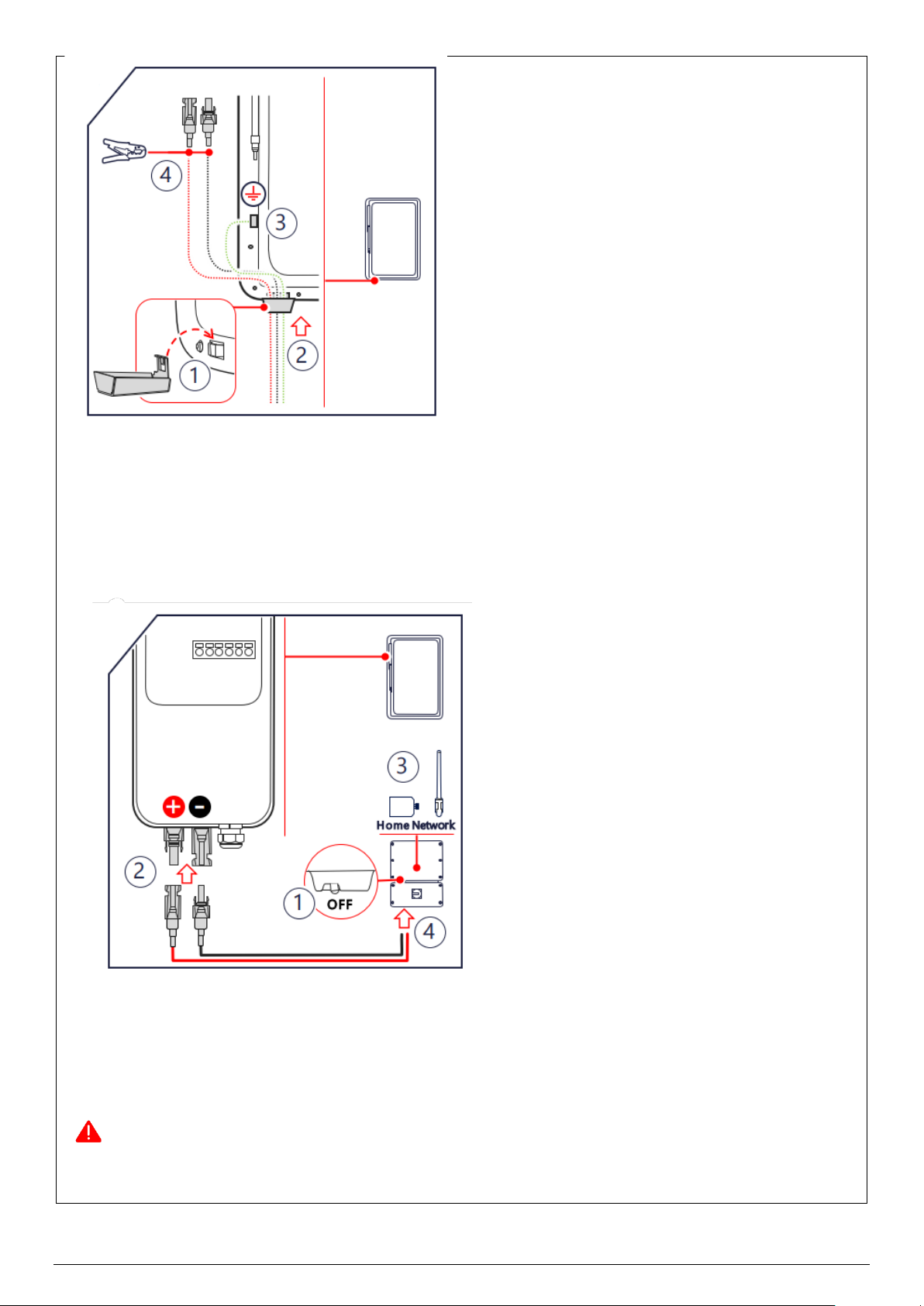
PREPARE CABLES
1. Mount the conduit holder.
2. Pass the DC cables and grounding cable through the conduit holder at the bottom of the battery.
3. Connect the grounding cable to the grounding terminal with a torque of 7.5 Nm.
4. Crimp the DC cables to the MC4 connectors (supplied) and tighten the MC4 connector glands with a
torque of 3.4Nm
6
10
CONNECT TO INVERTER
1. Make sure the inverter is OFF.
2. Connect the DC cables to the DC+ and DC- inputs. Observe correct polarity.
3. Install the SolarEdge Home Network plug-in and antenna in the inverter.
4. Connect cables to the inverter.
POWER ON AND ASSOCIATE
1. To power on and operate the battery, turn on the DC circuit breaker.
2. To associate with the inverter, move the battery’s ON/OFF/P switch to P for 2 seconds and then
release.
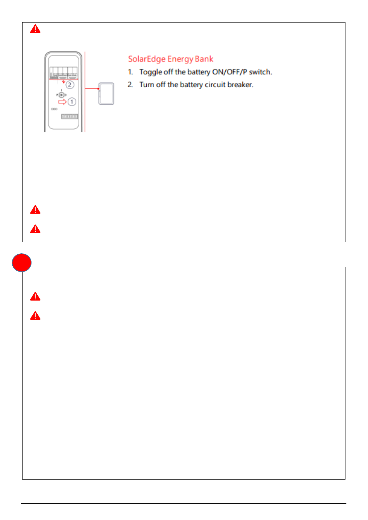
Warning: To power off the battery in case of emergency: Turn off the ON/OFF/P switch and DC
circuit breaker.

11
Cover an unused power supply ports with protective covers. Ensure the polarity of the cables is correct to
prevent any fuses from blowing.
NOTE: A DC circuit breaker is ‘in-built’ within the Battery unit. No additional external DC circuit breaker is
required.
Warning: Ensure all cable entries on the Battery are adequately sealed and the Battery IP
rating is maintained.
INVERTER
Follow instructions from SolarEdge User Manual to correctly connect the DC and AC power cables to the
Inverter.
Warning: Ensure Battery DC cable polarity is correct. Reverse polarity may cause damage to
the Battery.
Ensure each DC conductor is stripped and exposes appropriate amount of copper. Prepare DC cables and
accessories and place through battery cover, then crimp to battery terminals. Connect battery terminals to
the inverter
For all AC connections (both On-grid and Back-up), prepare the terminals and AC cables. Place the AC
cable through the terminal cover and screw the three cables tightly on the connectors. Lock the terminal
cover and screw up the terminal cap. Connect the assembled AC terminals onto the inverter.
INVERTER AC ISOLATOR (IF REQUIRED)
Wire the AC power cable from the Inverter to the Inverter AC Isolator in accordance with AS/NZS 3000.
MAIN SWITCH (INVERTER SUPPLY)
Wire the AC power cable from the Inverter AC Isolator (if present) or the Inverter, to the Main Switch
(Inverter Supply) in accordance with AS/NZS 3000 and the manufacturer’s instructions.
12
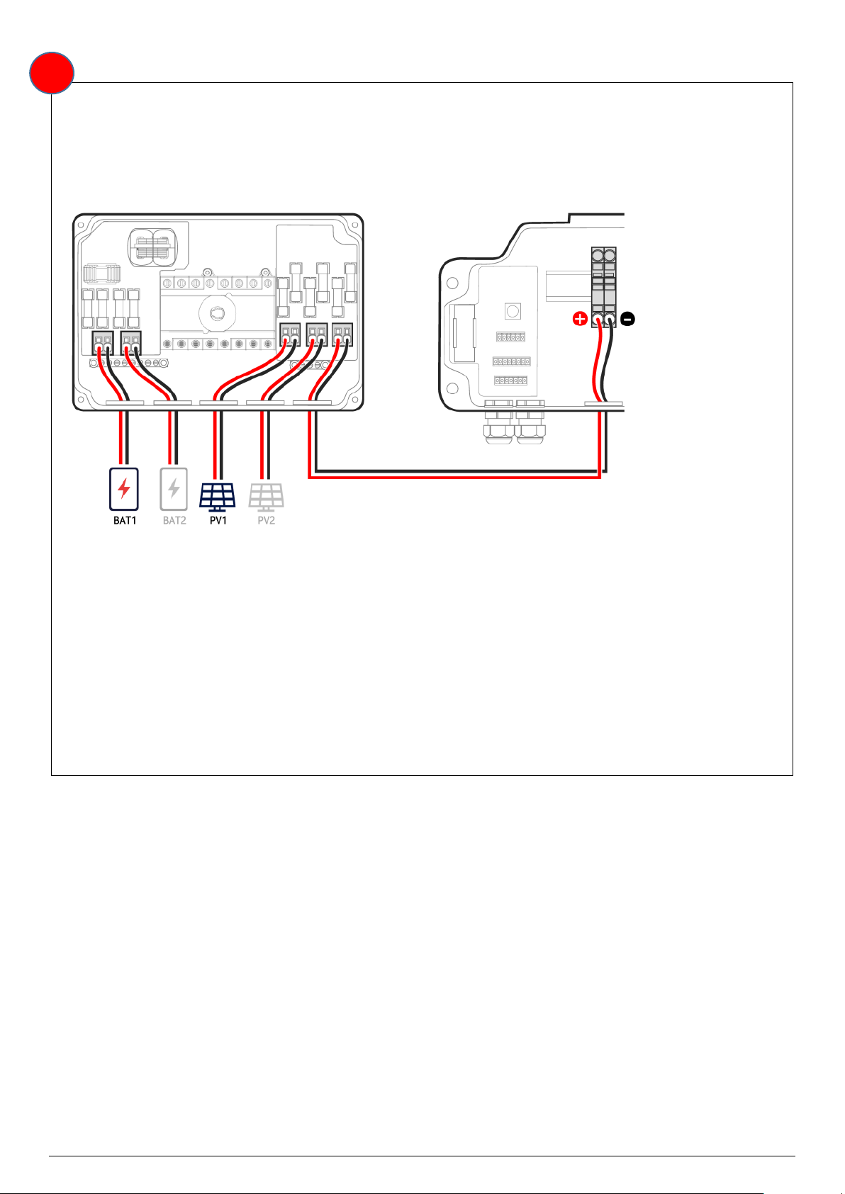
SolarEdge Combiner Box Use Cases (Optional)
With the Combiner Box
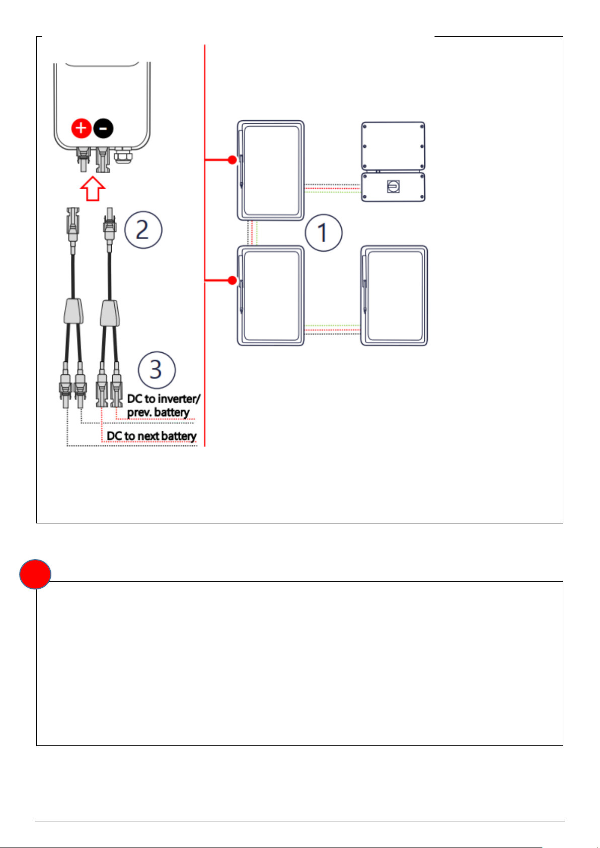
If three SolarEdge Home Batteries are to be connected, connect the DC cables from the battery/batteries
and the Power Optimisers to the Combiner Box. Then, connect the cables from the Combiner Box to the
DC terminals inside the inverter's Connection Unit
Without the Combiner Box
When one or two SolarEdge Home Batteries are to be connected, the DC cables from the battery and
Power Optimisers can connect directly to the DC terminals inside the inverter's Connection Unit. In this
case, the DC supplies from the battery/batteries and Power Optimisers must be combined because the
inverter has a single DC input.
Power Optimisers - If there are two or more PV arrays, combine their DC cables into a single home run
cable.
SolarEdge Home Batteries - When installing two SolarEdge Home Batteries, use branch connectors
(available from Solahart).
7
13
As the inverter's Connection Unit has a single DC input, crimp together the DC cable from the Power
Optimisers along with the batteries into one bootlace ferrule, terminating within the DC port of the
inverter.
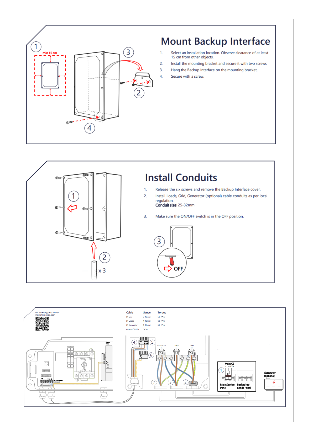
Backup interface (only available for Energy Hub inverters)
Read this before installing or operating the Backup Interface. Failure to do so or to follow any of the
instructions or warnings in this document can result in electrical shock, serious injury, or death, or may
damage the Backup Interface and other property.
Before operating the Backup Interface and inverter, ensure that they are properly grounded. The Backup
Interface and inverter must be connected to a grounded, metal, permanent wiring system, or an
equipment-grounding conductor must be run with the circuit conductors and connected to the equipment
grounding terminal or lead.
Opening the Backup Interface and repairing or testing under power must be performed only by qualified
service personnel familiar with the Backup Interface.
8
14
Connect Backup Interface

15
1. Turn off connection to grid by switching off the main circuit breaker.
2. Thread the L1, Neutral and Ground wires from the Main Service panel through the supplied ferrite
bead. Connect the wires to the L1, Neutral and Ground terminals.
3. Connect wires from the Backed-up Loads panel to the L1, Neutral and Ground terminals.
4. Use a CAT6 cable for the 12V connection between the inverter (Backup Interface connector) and
Backup Interface (6-pin RS485 connector).
5. Use a different CAT6 cable for communication between the inverter (Backup Interface connector)
and Backup Interface (6-pin RS485 connector).
6. Connect the Backup Interface’s CT to the inverter’s Energy Meter (L1 connector) using spare
wires of the communication CAT6 cable.
7. Optional, if a generator is installed: Connect wires from the generator to the L1, Neutral and
Ground terminals.

16
Commissioning
Warning: Before turning on the battery, please ensure that:
1. The equipment is levelled and installed firmly in a place where is convenient for operation
and maintenance. The installation place is clean and well ventilated.
2. The ground cable, power cables, communication cables and terminal resistance are
connected correctly and securely. Ensure that the polarity of all conductors is correct.
3. The CT is installed on and monitoring the appropriate active conductor and is correctly
orientated.
4. The cable ties meet the cabling requirements and are reasonably distributed. No cables
or ties are broken.
5. Unused ports are sealed.
6. The SolarEdge inverter is correctly commissioned following the user manual.
9
17
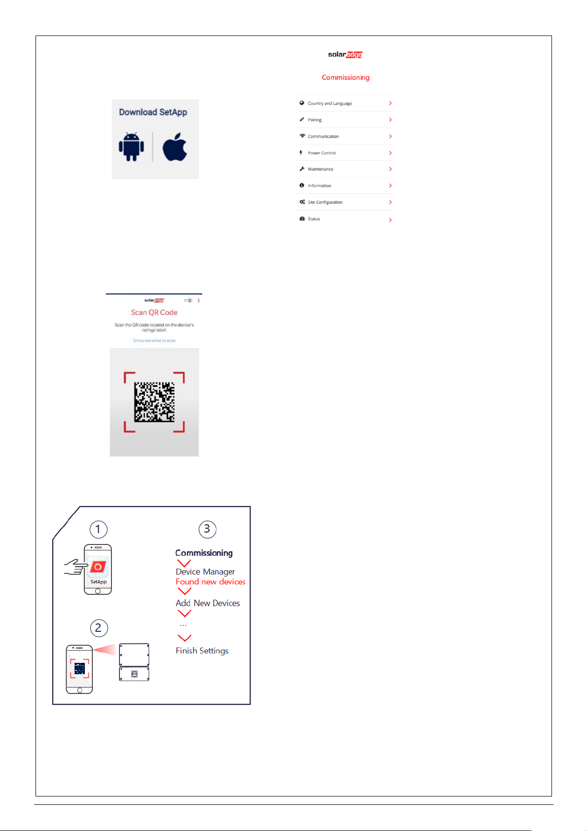
Configure installation
1. Run SetApp.
2. Scan the QR code on the inverter.
3. Follow the on-screen instructions
For post-installation settings, see Connection and Configuration application note.
The battery operation is managed by the SolarEdge inverter connected to the battery.
Configure installation
The purpose of the battery self-test is to check the battery's charge and discharge functionality.
1. Make sure the battery's circuit breaker switch is ON.

18
2. Switch the inverter ON/OFF/P switch to ON.
3. In SetApp, select Commissioning > Maintenance > Diagnostics > Self-Test > Battery Self-Test
> Run Test.
4. Wait for all tests to complete and check the results in the summary table. If any of the tests have
failed, see the table below for possible solutions:
Warning: If the battery system is not commissioned immediately after installation, turn off the
Battery Internal Circuit Breaker to avoid over-discharge and permanent damage to the Battery
cells. Once battery and inverter systems have been switched on and connected to the grid, both
systems will need to remain on at all times to ensure safe operation.
Note: Ensure firmware is updated as part of commissioning process of the Battery.
Monitoring Platform (Mandatory)
The Solahart warranty is conditional upon the Energy Bank being connected to the SolarEdge Monitoring
Platform (via an internet connection) for the entire duration of the Warranty Period.
The monitoring platform provides enhanced PV performance monitoring and yield assurance through
immediate fault detection and alerts at the module level, string level and system level.
No hardware or wiring is required to transmit data from the power optimizers to the inverter: the monitoring
sensors and transmittersare built into the SolarEdge power optimizer and solar inverter, andmeasurement
data is transmitted over the regular power lines.
Installers should contact their Solahart dealer to create their SolarEdge account.
10

19
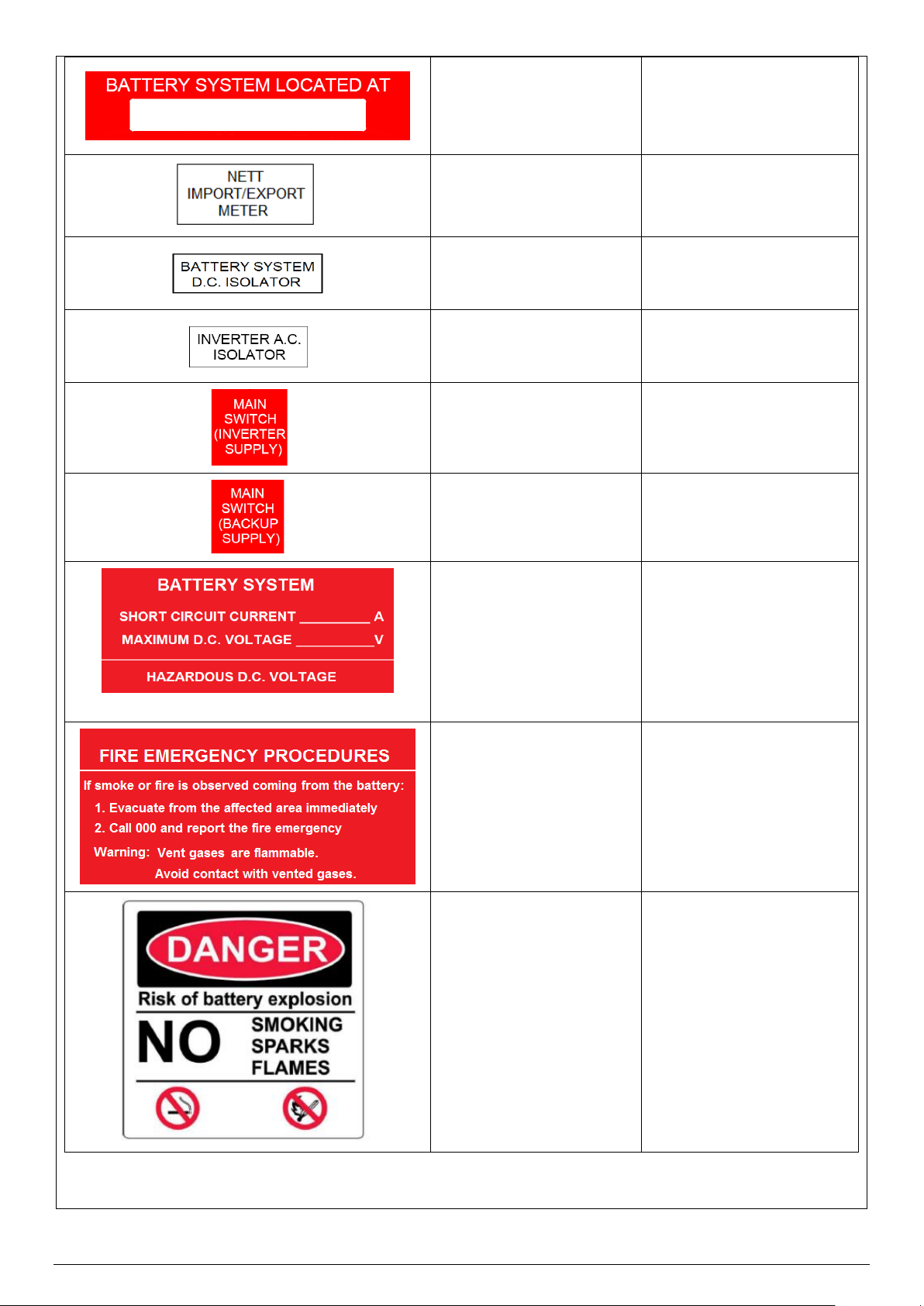
Labelling & Documents
This information is supplied here as a guide only. Additional labels may be required depending upon the
installation and local requirements. Labels must be constructed to AS 1319 and installed according to
AS/NZS 3000, AS/NZS 5139, AS/NZS 4777.1 and any local regulations. Refer to aforementioned
standards for more information.
Battery cables must be labelled according to AS/NZS 5139, section 7.
When segregation of circuits occurs, these circuits must be labelled according to AS/NZS 5139, section
7.
The purpose of labelling is to clearly indicate that the electrical installation has multiple supplies and which
circuits are affected by these supplies. Labelling also identifies the components that isolate the various
supplies. The following table details labels that are supplied for Solahart Battery Systems.
Item
Description
Location
Battery Safety Datasheet (SDS)- provided with the
Battery
Provided with the Battery
Place in document holder
at the main switchboard or
meter box
White text on
green background
On or immediately adjacent
to the meter box and main
switchboard
Black and white
Prominent position
adjacent to the Inverter
Black text on yellow
background
Directly below “Solar PV
and Battery Operating
Procedure” label
White text on
red background
Prominent position on main
switchboard
Note: This label replaces
the DUAL SUPPLY label
for PV systems.
11
20
White text on
red background
Prominent position on main
switchboard adjacent to
Inverter location label
Black text on
white background
Next to meter
Black text on
white background
Battery D.C. Circuit
Breaker
Black text
on
white background
Inverter AC isolator
(If required)
White text
on
red background
Inverter main switch in
switchboard
White text
on
red background
Inverter AC backup load
switch in switchboard
White text on
red background
Prominent position
adjacent to the Battery
White text on
red background
Prominent position
adjacent to the Battery
Black and white text with
symbols on
white background
Prominent position
adjacent to the Battery
This manual suits for next models
5
Table of contents
Other Solahart Solar Panel manuals


