EIP F2000P-TH-K02-a(B) User manual

Page 1of 2
C
Important safety information Warning
Always turn off power before installing, remove, cleaning controller.
Read all of the information in this manual before installing the controller.
Notice of the supply power voltage of the controller: 110VAC
Do not confuse them and do not install the controller over the voltages range.
Mounting and Wiring Diagram
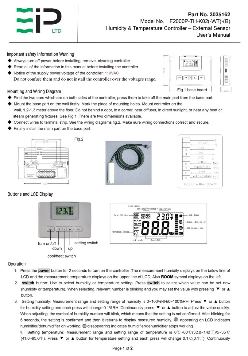
Find the two ears which are on both sides of the controller, press them to take off the
main part from the base part.
Mount the base part on the wall firstly: Mark the place of mounting holes.
Mount controller on the wall, 1.2-1.3 meter above the floor. Do not behind a door,
in a corner, near diffuser, in direct sunlight, or near any heat or steam
generating fixtures. See Fig 1. There aretwodimensions available.
Connect wires to terminal strip. See the wiring diagrams fig.2. Make sure wiring
connections correct and secure.
Finally install the main part on the base part.
Buttons and LCD Display
Operation
1. Press the power button for 2 seconds to turn on the controller. The measurement humidity displays on the below line of
LCD and the measurement temperature displays on the upper line of LCD. Also ROOM symbol displays on the left.
2. switch button: Use to select humidity or temperature setting. Press switch to select which value can be set now
(humidity or temperature). When selecting, relevant number is blinking and you may set the value with pressing ▼or ▲
button.
3. Setting humidity: Measurement range and setting range of humidity is 0~100%RH/0~100%RH. Press ▼or ▲button
for humidity setting and each press will change 0.1%RH. Continuously press ▼or ▲button to adjust the value quickly.
When adjusting, the symbol of humidity number will blink, which means that the setting is not confirmed. After blinking for
6 seconds, the setting is confirmed and then it returns to display measured humidity. appearing on LCD indicates
humidifier/dehumidifier on working. disappearing indicates humidifier/dehumidifier stops working.
4. Setting temperature: Measurement range and setting range of temperature is 0℃~60℃(32.0~140℉)/5~35℃(41.0~95.0
℉). Press ▼or ▲button for temperature setting and each press will change 0.1℃(0.1℉). Continuously press ▼or ▲
button to adjust the value quickly. When adjusting, the number of temperature blinks, which means that the setting is not
confirmed. After blinking for 6 seconds, the setting is confirmed and then it returns to display measured temperature.
appearing on right of the LCD indicates cooling/heating device on working. disappearing indicates s
cooling/heating device stops working.
5. set button : Use to select cooling or heating mode for temperature control . In cooling, symbol appears on the top left
turn on/off setting switch
down up
cool/heat switch
ON
ON
ROOM
AUTO
SET
temperature
lock temp
humidifying
dehumidifying
lock mode humidity
lock mode
temp. device on
RH device on
cooling/heating
Fig.1 base board
Fig.2
110vac
Part No. 3035160
Model No. F2000P-TH-K02-a(B)
Humidity & Temperature Controller – Internal Sensor
User’s Manual

Page 2of 2
of LCD. In heating, symbol appears on the top left of LCD. Press set button for 6 seconds until or appearing.
It indicates that the cooling/heating mode is locked. Now the working mode can not be changed.
6. Lock the set point:Press ▼and ▲at the same time for about 6 seconds until the symbol appearing on the top right
of LCD, which indicates that the set points of humidity and temperature are locked, after that, it’s impossible to adjust
humidity or temperature by ▼and ▲button.
7. Unlock set point : press ▼and ▲at the same time for about 7 seconds under the locking mode until the symbol disappearing.
Advanced Setup (V.A031)
Please use the below parameter setup carefully. Don’t change any default setting before you read and understand
all parameters.
Cut off power and press the ears on both sides to take off the main part from the base part. Then you will find a set
of four DIP switches DIP1~DIP4 on the top left of the circuit board.
DIP1: ON—parameterssetting OFF—normaluse (leavefactory:OFF)
DIP2: ON—Fahrenheit for temperature display
OFF—Celsiusfortemperaturedisplay (leavefactory:OFF)
DIP3: ON—Dehumidifymode; OFF—humidifymode (leavefactory:OFF)
DIP4: Ineffective for model F2000P-TH-K01
Put the DIP1 to ON (up is ON, down is OFF) and put the main part to the base part, then you can set up the following
parameters. Press switch button to select parameter and set up its value by press ▼or ▲.
Warning: must cut off power before open the controller.
LCD Parameter Range of setup Default
-1 RS485 communication address
(Ineffective for model F2000P-TH-K02) 1~255 1
-2 RS485 communication rate
(Ineffective for model F2000P-TH-K021) 1-4800, 2-9600, 3-14400, 4-19200, 5-38400 4
-3
RS485 communication odd/even calibration
and stop bit
(Ineffective for model F2000P-TH-K02)
1- none 1 stop bit
2- none 2 stop bits
3- odd calibration 1 stop bit
4- even calibration 1 stop bit
1
-4 Temperature modification ±3℃/±6℉0℃
-5 Humidity modification ±5%RH 0%RH
-6 Maximum limit of temperature setting 0~60℃/32~140℉35℃
-7 Minimum limit of temperature setting 0~60℃/32~140℉5℃
-8
Differential humidity to control the replay action 0~5%RH
For example, when it is set 2 and humidity set point is 40%RH, in humidify mode, the relay1 will be on
when measurement humidity< setting; if measurement humidity> (40+2)%RH, the relay1 will be off.
Dehumidifier working is in reverse mode.
2
-9
Differential temperature to control the relay action 0.0~3℃/0.0~6.0℉
For example, when it is set 1 and the setting temperature is 25℃, in heating mode, the relay2 will be on
when measurement temperature< setting; if measurement temperature>(25+1) ℃, the relay2 will be off. In
cooling mode it is in reverse mode.
1
-10 The state when the controller electrify again
after power broken
0- Turn off after electrify
1- Turn on after electrify
2- Keep the same state before power broken
2
Reset: in the state of parameter setup (DIP1=ON), cover the main part and turn it on. Press switch for about 25 seconds
until the controller turns off. The all parameters reset to default. After finish parameter setup, you must cut off the
power open the main part again, put the DIP1 to OFF, then the controller can work again.
Other EIP Controllers manuals
Popular Controllers manuals by other brands
Ledj
Ledj VersiLED 6 user manual

DSEGenset
DSEGenset DSE7110 Operator's manual and parts list
Johnson Controls
Johnson Controls M9200 Series quick start guide
Ascon tecnologic
Ascon tecnologic TLK 33 operating instructions
Hunter
Hunter Hydrawise HCC-FPUP quick start guide
AUTOTERM
AUTOTERM COMFORT BOILER CONTROL user manual
