AUTOTERM COMFORT BOILER CONTROL User manual


CONTENTS
INTRODUCTION ............................................................................................................................... 3
SAFETY INSTRUCTIONS .................................................................................................................... 3
LIABILITY .......................................................................................................................................... 4
1. GENERAL INFORMATION ......................................................................................................... 5
1.1. DISPLAY ........................................................................................................................... 5
1.2. ROTARY KNOB ................................................................................................................. 6
1.3. BACK BUTTON ................................................................................................................. 6
1.4. QUICK BUTTON ............................................................................................................... 6
1.5. LED INDICATORS ............................................................................................................. 6
2. MOUNTING AND CONNECTION ............................................................................................... 7
3. OPERATION AND SETTINGS ..................................................................................................... 8
3.1. MAIN MENU .................................................................................................................... 8
3.2. TIMERS ............................................................................................................................ 8
3.3. HEATING ....................................................................................................................... 10
3.4. VENTILATION ................................................................................................................ 12
4. SETTINGS ................................................................................................................................ 13
4.1. TIME/DATE .................................................................................................................... 13
4.2. DISPLAY ......................................................................................................................... 13
4.3. HEATER ........................................................................................................................ 13
4.4. BOILER .......................................................................................................................... 14
4.5. LED ............................................................................................................................... 14
5. ERRORS AND MAINTANACE .................................................................................................. 15
4.6. RESET ........................................................................................................................... 14

3
In case of questions about compatibility with older products please contact Your local
dealer or AUTOTERM Service center.
In case of any problems, we strongly recommend contacting certified service centers. Contact
information and the location of certified service centers can be found on our website
www.autoterm.com.
Please read carefully this manual before operating the AUTOTERM heaters.
This manual contains needful information in order to use this product correctly.
Disregarding of these instructions can void the warranty of the product, lead to
damage of product and/or property and be a risk to health.
If the heater /boiler is handled and/or installed improperly, there is a possibility of a
fire hazard and damage of property because fuel/electrical and hot water
components are being used. That is why all safety precautions, operation and
installation instructions must be observed.
For other languages of this manual, please visit www.autoterm.com/manuals.
SAFETY INSTRUCTIONS
Risk to health and/or damage of product
-The heater may only be used for the purposes specified in its respective operation manual.
-DO NOT use the heater in closed and/or poorly ventilated places (e.g. garage, workshop,
etc.) - Do not step on the heater or put any objects on it and in it.
-Do not put any body parts or items in to any of the air inlets or outlets of the heater. - For
air heaters. Do not allow hot air to be blown directly at people, animals or heat sensitive
objects.
-To avoid burns, do not touch the exhaust lines and the heater while it is operating.
-Caution: combiBOIL can heat water to up to 85°C (depending on the heating method).
-Direct un-mixed of domestic water can result in serious burns. Use a scald protection/pre-
mixing valve (recommended!) or set an appropriate target temperature on the Comfort
Boiler Control panel.
INTRODUCTION
Dear Customer!
Thank You for choosing the control panel AUTOTERM Comfort Boiler Control! We are doing
everything to make this product meet Your requirements, so its quality satisfies every customer.
Comfort Boiler Control is designed to be intuitive and comfortable to use, to ensure the best
experience when it comes to controlling Your climate and domestic water temperature.
The Comfort Boiler Control comes with a 5m long temperature probe specially designed for
AUTOTERM combiBOIL boiler.
AUTOTERM Comfort Boiler Control is compatible with all AUTOTERM AIR Series heaters.
Some older versions of AIR heaters may not support some of the functions.
4
Risk of fire and explosion
-The heater is not designed for installation and use on any type of ADR transportation vehicle.
-When refueling heater must be shut down. Note: the shutdown process can take up
to 10 minutes.
-The vehicle where the heater is installed must be equipped with a fire extinguisher.
-Do not cover the heater with clothing, pieces of fabric and so on, and do not place such
objects in front of the air intake pipe or inlet and output of the heated air.
-Do not use or install the heater in places, where flammable vapors or gases or large amounts
of dust may form and accumulate.
-Do not use or install the heater in places, where flammable and/or explosive items or
substances are stored.
-Avoid contact with any flammable objects with the heater’s exhaust pipe.
Risk of damage due electrical nature
-Do not connect/disconnect any wiring of the heater while it is connected to the power supply
or operating.
-Do not connect the heater to the power circuit of the vessel, when the engine is operating
and there is no battery.
-The heater can be switched on again 15-20 seconds after disabling indications on the control
panel, which means that the heater has shut down.
-The length of the control panel wiring cannot exceed 15 meters.
Personnel certified by AUTOTERM is needed
-In case of faults in the operation of the heater, contact specialized repair organizations
authorized by AUTOTERM.
LIABILITY
The manufacturer is not liable for any damage as a result of installation and repairs by
uncertified personnel and/or use of third-party parts and accessories without the
approval of the manufacturer.
In case of any problems, we strongly recommend contacting certified service centers. Contact
information and location of certified service centers can be found on our website
www.autoterm.com.

5
1. GENERAL INFORMATION
1. DISPLAY
3. BACK BUTTON
5. LED INDICATORS
2. ROTARY KNOB
4. QUICK BUTTON
1.1. DISPLAY
•While in sleep mode:
odisplay is inactive;
oscreensaver shows:
─temperature;
─current time and date;
─symbol of set operation mode, if active.
─ water temperature
─ frost protection
Control panel goes in to sleep mode after the time of inactivity set in
display settings.
Sleep mode is canceled by pressing the knob or the back button.
•While active display shows:
ocurrent time;
opower supply voltage;
otemperature;
oset operation mode, if active;
oactive timers;
owater temperature;
ofrost protection, if active
To access the main screen control panel has to be woken from sleep
mode.
For air heater temperature displayed depends on the temperature sensor selected.
Description of each symbol and screen layouts can be found in their respective sections
of the manual.
5
1
2
5
3
4

6
When an operation mode is active, the respective symbol is displayed on the main screen
(under the current time) and it works as a quick menu. By rotating the knob three options can
be accessed:
•Active operation mode
settings
•Shut off the heater
•Access the main menu
Confirm selection by pressing the knob.
1.2. ROTARY KNOB
The rotary knob is the main button for navigation through the interface.
•When control panel is active pressing the knob enters the main menu. After that pressing
the knob confirms selected item or setting.
•Turning right selects next item or increases value of selected setting.
•Turning left selects previous item or decreases value of selected setting.
•While control panel is in sleep mode, turning the knob to either side allows to change the
set temperature/power level of the active mode. Changes are applied without
confirmation.
1.3. BACK BUTTON
Back button is used to return to the previous screen by pressing it once.
1.4. QUICK BUTTON
Quick button can be used to start or stop the heater without entering the main menu or quickly
enabling or disabling timers.
•While the heater is off, pressing the button once opens the “Heating” menu.
•While the heater is off, long-pressing the button for 2 seconds starts the heater with
previous settings (Display message: “Starting…”).
•While the heater is operating, long-pressing the button for 2 seconds switches off the
heater (Display message: “Switching off…”).
•While the heater is operating (and in sleep mode), pressing the button once opens the
settings of the active operation mode. Changes are applied after confirmation.
•In the menu “Timers” pressing the button once enables/disables the selected timer (for
this action timer has to be set beforehand).
1.5. LED INDICATORS
LED indicators are used to indicate the operating mode or status of the heater:
•RED – heater is working in heating mode;
•BLUE – heater is working in ventilation mode;
•GREEN – heater is switching off (purge mode);
•RED (blinking combined with display message) – an error has occurred;
•LIGHT GREEN (one blink every 5 seconds) – a timer has been enabled.
7
2. MOUNTING AND CONNECTION
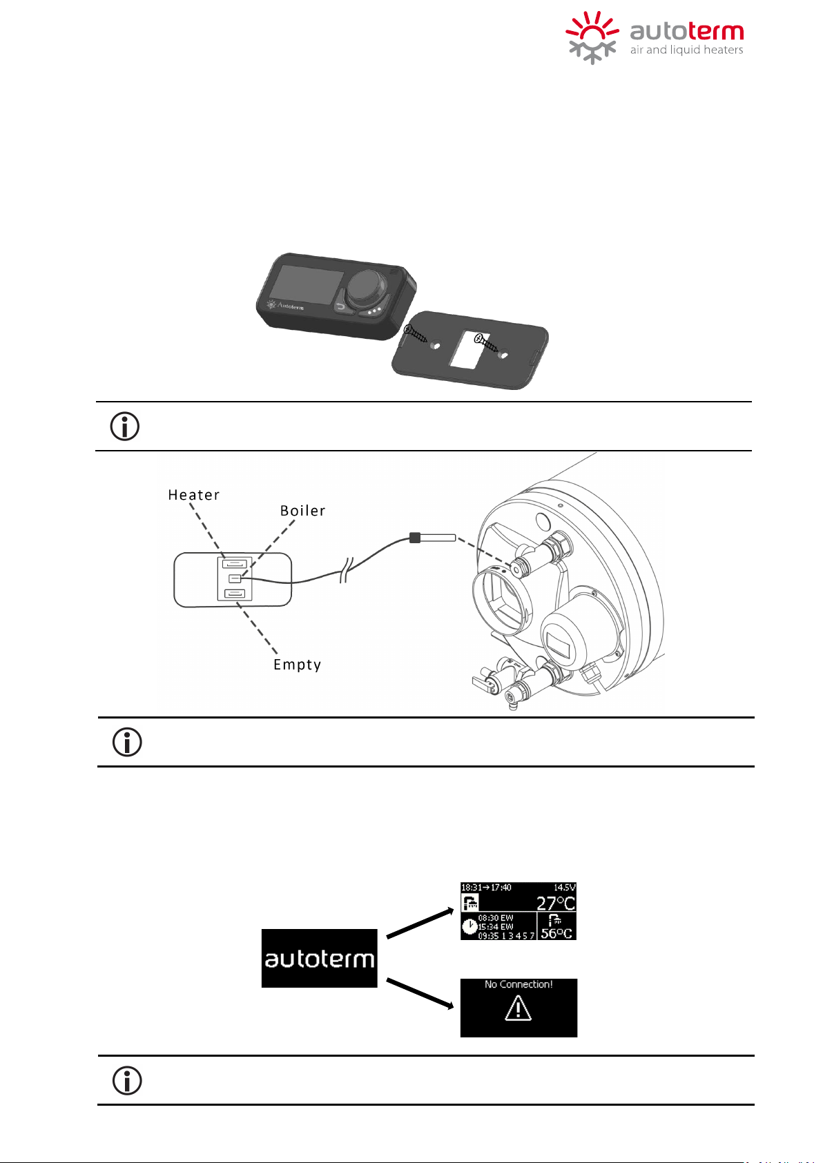
Control panel can be mounted using screws or double-sided adhesive tape.
For mounting with screws, gently remove the back panel using a thin flat screwdriver, by prying
it from the middle of one of the sides. Then screw the back panel to your desired surface.
For mounting with double-sided adhesive tape, before installation degrease the back of the
control panel and the desired surface.
To increase the length of control panel wiring, use only designated extension wirings.
When connected to the power supply control panel turns on automatically.
When turned on LED indicators light up, while showing AUTOTERM logos on the display.
Connection process takes approx. up to 20 seconds. If connection is established display shows
main screen. If connection fails message “No connection!” is displayed.
After disconnecting the control panel form the power supply time and date must be
reset. The rest of the settings, such as set timers, remain saved.
Connect temperature sensor to boiler temperature sensor socket and control panel before
connecting heater to power. Temperature sensor cable length is 5 meters.

8
3. OPERATION AND SETTINGS
3.1. MAIN MENU
The main menu can be accessed from the main screen by pressing the rotary knob once.
Navigate through the menu by turning the knob. To enter the selected menu, press the knob
once.
TIMERS
Is used to set and enable/disable up to 3 timers.
HEATING
Is used to set different heating modes, depending on the
connected heater.
VENTILATION
Is used to set ventilation mode (except for AIR 8D and liquid
heaters).
SETTINGS
Is used to change general settings of the control panel and
heater.
3.2. TIMERS
In “Timers” menu up to 3 timers can be set to start the heater at a
specific time in desired mode for desired duration.
To set timers select the “Timers” menu from the main menu by pressing
the knob once.
Choose one of three timers by rotating the knob and pressing the knob once
to confirm the selected timer.
The default values of the timers are 0:00 –ED –Heating.
Quick button ( ) can be used to enable/disable previously set timers.
After selecting a timer, choose to enable or adjust the timer by rotating the
knob and pressing the knob once to confirm one of the options.
BOILER Is used to set water heating only mode. The heater will
heat, and switch on/off following water temperature.
9
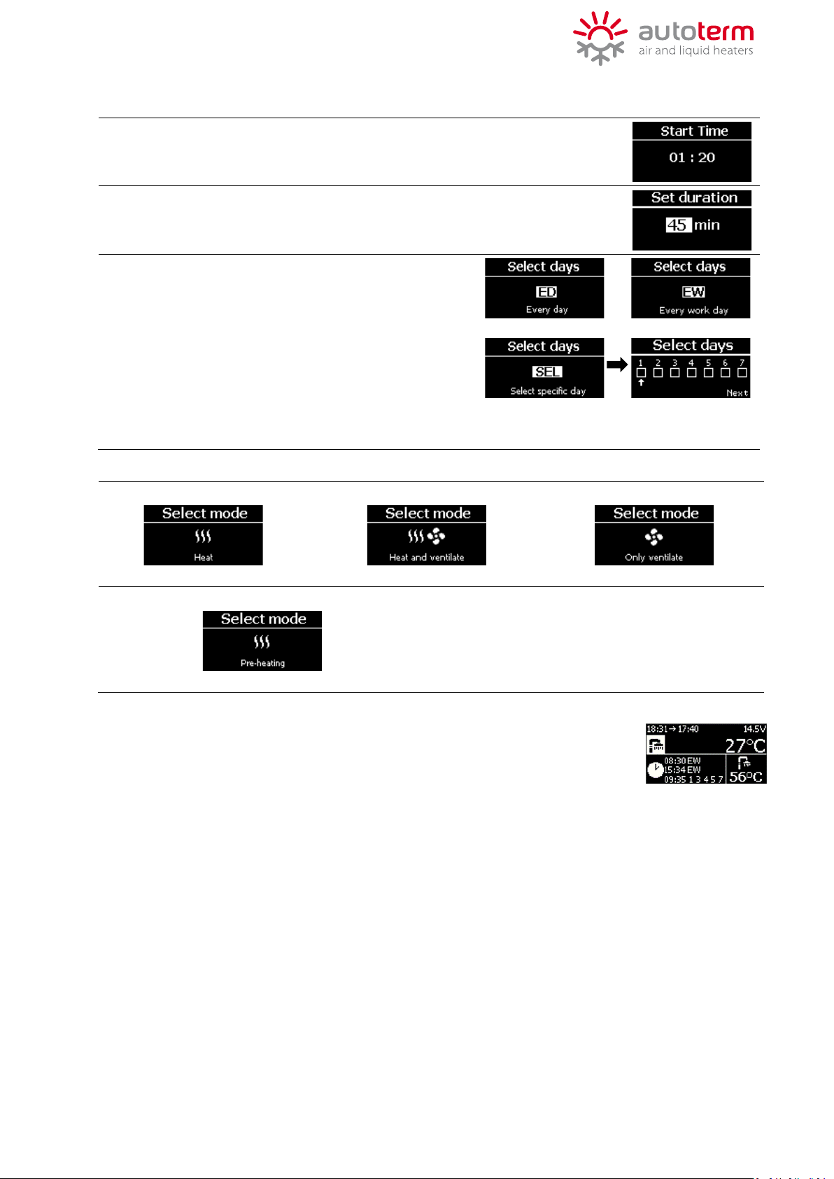
Editing the timer
Set the time of day for heater to start:
•Set hours and confirm;
•Set minutes and confirm.
Set working duration of the heater.
Duration can be set from 30min to 720min* with increasing step of 5min.
*up to 120min for liquid heaters
Set days for heater to start, where:
•ED (Every Day) – heater starts every day of the
week;
•EW (Every Workday) – heater starts every day from
Monday to Friday;
•SEL (Select specific day) – heater starts only on
specified days, where:
1 – Monday
3 – Wednesday
5 – Friday
7 – Sunday
2 – Tuesday
4 – Thursday
6 – Saturday
Set the operation mode for air heaters:
•Heating mode
•Heat + Ventilation mode
•Ventilation mode
Set the operation mode for liquid heaters:
•Pre-heating mode
When all the parameters are set message “Saved” is shown on the display and
the timer is enabled automatically. Enabled timers can be seen on the bottom
part of the main screen. LED indicators will blink light green once every 5sec
when timer is enabled.
10
3.3. HEATING
In “Heating” menu different operation modes for heating can be set,
depending on the connceted heater.
To set heater modes select the “Heating” menu from the main menu by
pressing the knob once and then select one of the heating modes:
Temperature can be set in a range of 0°C up to 30°C, with step of 1°C.
Work time can be set by turning the knob in either direction, in a range of
30 min up to infinity (or vice versa) by a step of:
•5min up to 2h;
•20min up to 12h;
•after 12h next step is ∞.
It is impossible to switch to any of heating modes while heater is operating in ventilation
mode!
Heating modes for air heaters:
TEMPERATURE MODE –Heater will maintain set temperature by reducing the
heating power, without shutting off the combustion process.(*)
POWER MODE – Heater will operate constantly at set power level.
HEAT + VENTILATION –
Heater will operate till the temperature is reached 1°C above the
set temperature, shut off the combustion process and start to
ventilate till the temperature drops 5°C below the set
temperature. When temperature drops, heating starts again.
THERMOSTAT MODE –
Heater will operate till the specified temperature is reached then
shuts off the combustion process and ventilation. After the
temperature drops by specified degrees heating will start again.
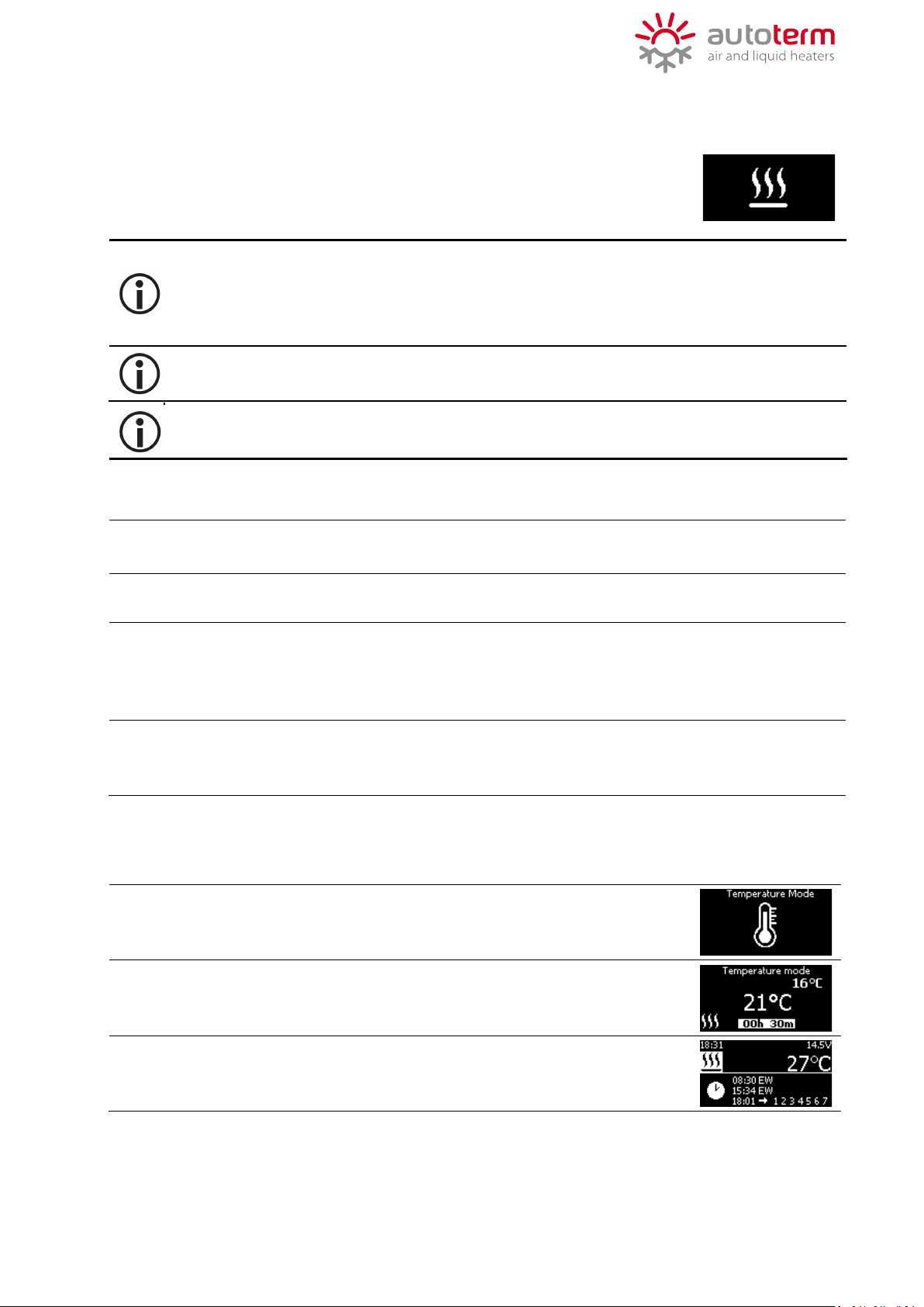
Setting Temperature mode
Select “Temperature mode” from the menu.
Set temperature and confirm.
Set work time and confirm.
When mode is active, respective symbol is shown on the main screen.
*The temperature mode for Air 2D 12/24V and 4D 12/24V heaters in the 6355, 6350, 6260,
and 6265 series versions have a new algorithm. In this mode, the heater acts normally by
lowering power when it gets near the set temperature. However, if it goes past the
temperature setpoint, the heater will turn off and wait until the temperature drops by 3
degrees below temperature setpoint before starting again.
For Flow 5 and Flow 14 v2 liquid heaters maximum operation time in pre-heating
mode is 8 hours.

11
Setting Power mode
Select “Power mode” from the menu.
Set power level and confirm.
Set work time and confirm.
When mode is active, respective symbol is shown on the main screen.
Setting Heat + Ventilation mode
Select “Heat + Ventilation” from the menu.
Set temperature and confirm.
Set work time and confirm.
When mode is active, respective symbol is shown on the main screen.
Setting Thermostat mode
Select “Thermostat mode” from the menu.
Set temperature and confirm.
Set work time and confirm.
When mode is active, respective symbol is shown on the main screen.
Default value for MAX temperature rise is 1°C and MIN temperature drop is 2°C. These settings
can be changed in “Settings -> Heater -> Advanced -> Thermostat”.

12
Water heating mode
Select “Water heating mode” from the main menu.
Set water temperature and confirm min 50°C max 75°C.
Set work time and confirm.
When mode is active, respective symbol is shown on the main screen.
Default value is 50°C. These settings can be changed in “Settings -> Boiler-> Hysteresis”(default
range 10°C.
Setting Ventilation mode
Set power level and confirm.
Set work time and confirm.
When mode is active, respective symbol is shown on the main screen
13
4.3. HEATER (for air heaters)
•TEMP. SENSOR – change the temperature sensor by which the temperature is read:
oBY PANEL – temp. sensor built in the control panel;
oBY HEATER – temp. sensor built in the heater;
oEXTERNAL – externally connected temp. sensor (sold separately). This option is
visible only when external temp. sensor is connected.
Temperature sensor cannot be changed while heater is operating in “Power mode” or
“Thermostat mode”.
•ADVANCED – change advanced settings of the heater:
oSHUTDOWN
VOLTAGE
– set voltage and time for battery protection.
If the actual voltage of the power supply is lower than the set voltage
for the set duration, heater shuts down and operation modes cannot
be activated.
oTHERMOSTAT – change default values for temperature rise and drop for thermostat
mode. MAX from 1°C to 3°C, MIN from 1°C to 7°C;
oINFO – displays information about serial numbers and software versions:
▪Control panel serial number (s/n)
▪Control panel software version (f/w)
▪Heater serial number (s/n)
▪Heater software version (s/w)
▪Total heater operating hours (w/t)
ThThe e ““ININFOFO”” sectiosectionn ccanannnotot bbe e accaccessedessed wwhhileile hheaeatterer isis operatoperatiinng.g.
4. SETTINGS
In the “Settings” menu general settings for control panel and advanced
settings for the heater can be changed. Available settings are displayed
depending on the connected heater.
To enter the “Settings” menu select it from the main menu by pressing the knob once and select
one of the options.
Turn the knob to change value, press the knob to confirm set value.
4.1. TIME/DATE
•Set the current time and date.
4.2. DISPLAY
•LANGUAGE –change the display language of the control panel.
•UNITS –Change displayed format of units. Metric (24h time format, °C) or
Imperial (12h time format, °F).
•BRIGHTNESS –change the brightness level of the display.
•SLEEP MODE –change the time after which control panel goes to sleep mode.
Enable/Disable screen saver.

14
oINFO – displays information about serial numbers and software versions:
▪Control panel serial number (s/n)
▪Control panel software version (f/w)
▪Heater serial number (s/n)
▪Heater software version (s/w)
▪Total heater operating hours (w/t)
The “INFO” section cannot be accessed while heater is operating.
Default algorithm that does no allow the water temperature to rise above +80°C.
When water temperature reaches +80°C heating will stop completely an error
message will appear (Water overheating!).
Passive boiler protection!
4.5.LED
•Turn on or off the LED indicators.
4.6.RESET
•Reset the control panel to factory settings.
•BOILER SETTINGS –change boiler settings:
oHYSTERESIS –water heating hysteresis defines heating start and stop sequence.
Value can be adjusted from 10°C to 20°C.
oTEMPERATURE
LIMIT
–controls water temperature in any heating mode. The goal of this
function is to not allow water to pass above the desired water
temperature. Value can be adjusted from 60°C to 75°C. When the
active protection value is reached, heating will switched off and
ventilation will start to cool down water by 10°C from setpoint. After
cooldown heater will start heating in the previous heating settings.
–protects against negative temperature.
When the temperature reaches (<1°C air temperature
and/or <1°C degree water, heating will start and heat
till water +15°C, air +7°C, heating will stop after both
conditions are met).
oo FROSTFROST
PROTECTIONPROTECTION
NOTE: The frost protect function if it is on stands above all other settings in case the
panel is adjusted to 0°C in any heating mode and room or boiler temperature drops
lower than 1°C it will cancel previous heating settings.
4.5.LED
BOILER
4.4.

5. ERRORS AND MAINTANACE
Maintenance and repair of the heater should only be performed by personnel trained
and qualified by AUTOTERM.
ERROR MESSAGE FAULT CODE BY HEATER
AIR HEATERS FLOW 5 / Flow 14D v2 FLOW 14D
Air Ducting or
Outlet! 1;2 -
Service! 4; 5; 6; 9; 10; 13; 16; 27; 28
7; 11; 29; 32; 34; 36; 37 3; 24; 25; 26; 3
Overvoltage! 12
Undervoltage! 15
Low voltage! 35 -
Fuel pump! 17 17; 22 17
No connection! 20; 30 20; 30; 50 20
Overheating! 31 1 1; 2
Heater Locked! 33 37 -
Check fuel system! 8; 78 29; 78
Coolant
pump/circuit! - 14
If the water temperature reaches 80 degrees, the heater will shut down and
an error message will appear.
In case of an error LED indicators blink red once every 5 seconds and an error
message is displayed depending on the fault and the heater connected. Full
descriptions of the fault codes can be found in the respective manual of the
heater.
REMINDER!
To ensure reliable operation of the heater, it is required to start it once in 30 days on
max heating power for 30 minutes including the warm seasons of the year, when heater
is out of operation.
This action is necessary to remove any viscous film sediments on moving parts of the
fuel pump. Failure to do so may lead to premature failure of the heater.
That is why AUTOTERM Comfort Boiler Control has a built-in reminder to
start the heater for 30 minutes if it has been out of operation for at least
30 days. After 30 days of inactivity since the last start red LED indicators
blink once in every 5 seconds and message is displayed.
Accept the start by pressing the knob once. Decline the start by pressing the “Back” button
once. In case of a decline, this message is repeated if the heater hasn’t been launched in any
of the heating modes.
15

Table of contents
Other AUTOTERM Controllers manuals


Popular Controllers manuals by other brands

Lenze
Lenze 9200 Series operating instructions

Samson
Samson 42-20 Mounting and operating instructions

Pego
Pego ECP200 BASE Series Use and maintenance manual

DMC
DMC TSC-10/IC instruction manual

Motorola
Motorola MaraTrac Advanced Control Head operating instructions

National Instruments
National Instruments VXI Series Getting started


