Warner Electric MCS-805 Series User manual

MCS-805 Series Clutch/Brake Controls
Installation Instructions
819-0556
P-8854-WE

2Warner Electric • 800-825-9050 P-8854-WE • 819-0556
Introduction
Warner Electric’s MCS-805-1 and MCS-805-
2 series clutch/brake controls are designed for
operation with Warner Electric electrically released
brakes. The correct brake release voltage is a
specific point between 35-75VDC. This point is
set by adjusting the control at the time of brake
installation. These controls are factory set for 60
volts output.
The MCS-805-1 and MCS-805-2 controls operate
from 115/230VAC single phase input power.
Switching may be provided on either the AC or DC
side of the control.
The MCS-805-1 and the MCS-805-2 have an
internal adjustment potentiometer that is used for
the release band adjustment. The MCS 805-2 is
similar to the MCS-805-1 except that it has torque
adjustment capability for soft stop applications.
The MCS 805-2 requires two switching circuits
when used for those applications requiring soft
engagement.
Contents
Introduction .............................2
Specifications ...........................3
Installation ..............................4
Dimensions .............................5
Connection .............................5
Warranty .......................back cover
Failure to follow these
instructions may result in product damage,
equipment damage, and serious or fatal injury
to personnel.

Warner Electric • 800-825-9050 P-8854-WE • 819-0556 3
Specications:
Input power:
• MCS-805-1 115/230VAC ± 10%,
50/60Hz, single phase.
• MCS-805-2 115/230VAC ± 10%,
50/60Hz, single phase
Output:
MCS-805-1 35-75VDC, 0.40 amps
MCS-805-2 35-75VDC, 0.40 amps
Switching inputs:
(external to control, supplied by customer)
• DC switching: single pole, single throw.
Minimum contact rating 1 amp, 120 VDC.
• AC switching: single pole, single throw.
Minimum contact rating 1 amp, 120 VAC.
Ambient temperatures:
-20° to 150°F (-29° to 65°C)
Circuit protection: (fusing)
500 ma Fuse-fast act (5 mm x 20 mm)
Adjustments:
Release band adjustment (via internal
potentiometer)
MCS-805-2 only: Torque adjust (via external
potentiometer)
Wiring Entrance:
Two 7/8” diameter conduit entrance holes
located on the bottom and on the top of the
control chassis.
Reorder Information
Model Part No.
MCS-805-1 6090-448-006
MCS-805-2 6090-448-007
Mounting
Any vertical, horizontal, or angled surface is suitable
for mounting the MCS-805-1 or MCS-805-2.
Follow these procedures to mount your control:
A. Remove the front cover by removing the top
retaining screws.
B. Set the control on the mounting surface and
mark for the four mounting holes in accordance
with dimensions.
C. Install and tighten the four screws.
The control is now ready to be wired.
To avoid injury (or even death),
always make certain all power is off before
attempting to install this control or any
electrical equipment. Do not touch the board if
power is applied.

4Warner Electric • 800-825-9050 P-8854-WE • 819-0556
Installation
A. For 115VAC: Connect power supply to
terminals 1 and 2. Insure AC input switch is in
the 115 position. For 230VAC: Connect power
supply to terminals 1 and 2. Insure AC input
switch is in 230 position.
B. A chassis ground should be provided as a non-
current conducting ground wire (color coded
green). Connect this ground to the PC board
screw labeled “Chassis GND.”
C. Switching.
• For switching DC side: switch must be
connected to terminals 3 and 4. Switch
open will allow brake to be engaged. Switch
closed will release the brake. For MCS-
805-2 Only: Switch open will allow brake to
be partially engaged and AC power off will
allow brake to be fully engaged.
• For switching AC side: Line power off will
allow brake to be engaged. Line power on
will release brake. Install a jumper between
terminals 3 and 4.
D. Connect the positive terminal of the brake
to terminal 6 on the control and the negative
terminal of the brake to the terminal 5 on the
control.
Brake Release Adjustment
When setting the MCS-805 control, the objective
is to achieve armature release by adjusting the coil
voltage so it counteracts the permanent magnet to
the maximum extent possible. Proceed as follows:
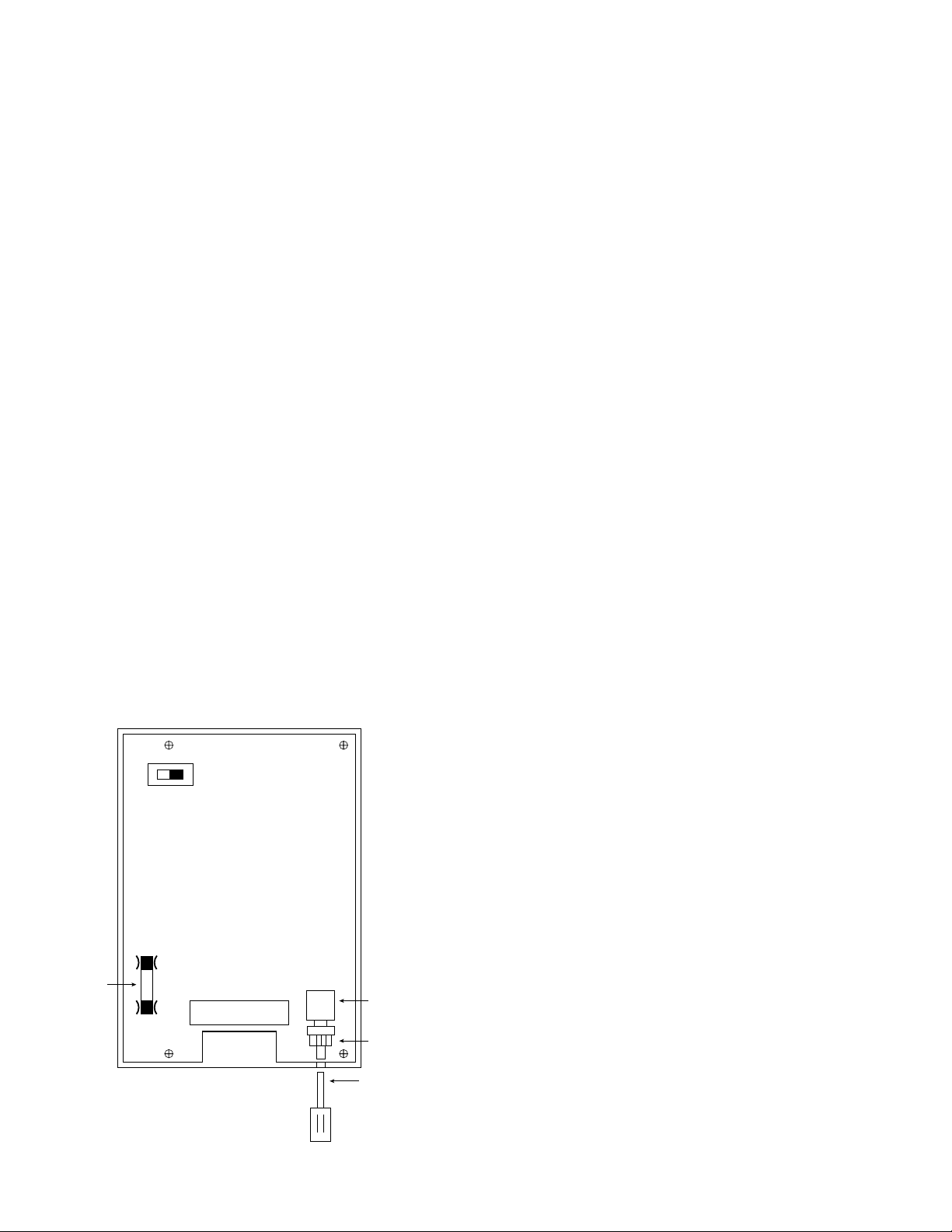
A. Remove the 3/8” hole plug from the housing
for the release adjust potentiometer. While
holding the potentiometer locking mechanism
with 1/2” wrench, loosen the 7/16” locking
nut on the adjustment potentiometer. Ensure
user connected switch S1 is closed (see
Connections on page 5). Turn on AC power.
Turn the potentiometer adjusting screw (through
access hole in enclosure) to the maximum
counterclockwise position. Slowly turn the
adjustment screw clockwise until the brake
armature disengages from the magnet. If the
usual autogap spring is used, this will normally
cause the armature to separate approximately
1/32” from the magnet. If the autogap is not
used, an external release force of approximately
5-10 pounds should be applied by hand, to
detect the point of armature release. Using a
voltmeter, note and record the voltage at this
point.
B. Turn the adjusting screw to the maximum
clockwise position that will normally cause
the armature to be reengaged. If the armature
does not make contact, it should be physically
moved into contact, with caution exercised to
prevent fingers from being injured.
C. Turn the adjusting screw slowly counterclock-
wise until the armature releases through the
same technique as used under (A). Note and re-
cord the voltage, which will be somewhat higher
than the value noted under (A). Adjust the final
voltage setting to the mid-point between the
two readings.
D. While holding the potentiometer locking
mechanism with 1/2” wrench, tighten the
locking nut with 7/16” wrench. Plug access hole
with 3/8” hole plug previously removed. The
brake is then ready for normal operation.
For MCS-805-2 Only: Set partial engagement
torque using the external potentiometer. Switch
connected to terminals 3 and 4 must be open
to make this adjustment. A setting of 10 gives
maximum torque.
115 230
1 2 3 4 5 6
Release
Adjust
Potentiometer
Locking Nut
Screwdriver
Adjust
Chassis
GND
Fuse:
500 ma
FA

Warner Electric • 800-825-9050 P-8854-WE • 819-0556 5
Top and Bottom
3-7/16"
1.000"
2-1/32"
7/8" Diameter Knockouts
for 1/2" Conduit Both Ends
Typical
Back
3-3/4"
5-1/16"MAX
6"
4-13/16"
9/16"
9/32" Diameter
4 Mounting Holes
Clearance for 1/4" Screw
Side
3-7/16"
Front
7-1/8"
1 2 3 4 5 6
AC INPUT
115/230 VAC
50-60 Hz
AC INPUT
115/230 VAC
50-60 Hz
BrakeS1
(DC Switching)
S1
S1Closed - brake released
S2Open - brake engaged
805-1
OPTIONS
Chassis
GND
1 2 3 4 5 6
BrakeJumper
(AC Switching)
Chassis
GND
1 2 3 4 5 6
AC INPUT
115/230 VAC
50-60 Hz
BrakeS1
S2
S2Closed - brake released
S2Open - brake engaged
S1 Closed - full engage volts
S1 Open - reduced engage volts
(torque adjust)
805-2
ONLY
Chassis
GND
Dimensions
Connections

Warranty
Warner Electric, Inc. warrants that it will repair or replace (whichever it deems advisable) any product
manufactured and sold by it which proves to be defective in material or workmanship within a period
of one (1) year from the date of original purchase for consumer, commercial or industrial use.
This warranty extends only to the original purchaser and is not transferable or assignable without
Warner Electric, Inc.’s prior consent.
Warranty service can be obtained in the U.S.A. by returning any defective product, transportation charges
prepaid, to the appropriate Warner Electric, Inc. factory. Additional warranty information may be obtained by
writing the Customer Satisfaction Department, Warner Electric, Inc., 449 Gardner Street, South Beloit,
Illinois 61080, or by calling 815-389-3771.
A purchase receipt or other proof of original purchase will be required before warranty service is rendered. If
found defective under the terms of this warranty, repair or replacement will be made, without charge, together
with a refund for transportation costs. If found not to be defective, you will be notified and, with your consent,
the item will be repaired or replaced and returned to you at your expense.
This warranty covers normal use and does not cover damage or defect which results from alteration, accident,
neglect, or improper installation, operation, or maintenance.
Some states do not allow limitation on how long an implied warranty lasts, so the above limitation may not apply
to you.
Warner Electric, Inc.’s obligation under this warranty is limited to the repair or replacement of the defective
product and in no event shall Warner Electric, Inc. be liable for consequential, indirect, or incidental damages
of any kind incurred by reason of the manufacture, sale or use of any defective product. Warner Electric, Inc.
neither assumes nor authorizes any other person to give any other warranty or to assume any other obligation or
liability on its behalf.
WITH RESPECT TO CONSUMER USE OF THE PRODUCT, ANY IMPLIED WARRANTIES WHICH THE
CONSUMER MAY HAVE ARE LIMITED IN DURATION TO ONE YEAR FROM THE DATE OF ORIGINAL
CONSUMER PURCHASE. WITH RESPECT TO COMMERCIAL AND INDUSTRIAL USES OF THE PRODUCT,
THE FOREGOING WARRANTY IS IN LIEU OF AND EXCLUDES ALL OTHER WARRANTIES, WHETHER
EXPRESS OR IMPLIED BY OPERATION OF LAW OR OTHERWISE, INCLUDING, BUT NOT LIMITED TO, ANY
IMPLIED WARRANTIES OF MERCHANTABILITY OR FITNESS.
Some states do not allow the exclusion or limitation of incidental or consequential damages, so the above
limitation or exclusion may not apply to you. This warranty gives you specific legal rights and you may also have
other rights which vary from state to state.
Changes in Dimensions and Specications
All dimensions and specifications shown in Warner Electric catalogs are subject to change without notice.
Weights do not include weight of boxing for shipment. Certified prints will be furnished without charge on request
to Warner Electric.
P-8854-WE 819-0556 7/20
www.warnerelectric.com
449 Gardner Street
South Beloit, IL 61080
815-389-3771
This manual suits for next models
2
Table of contents
Other Warner Electric Controllers manuals