eisfink varithek acs 600 EasyClean User manual
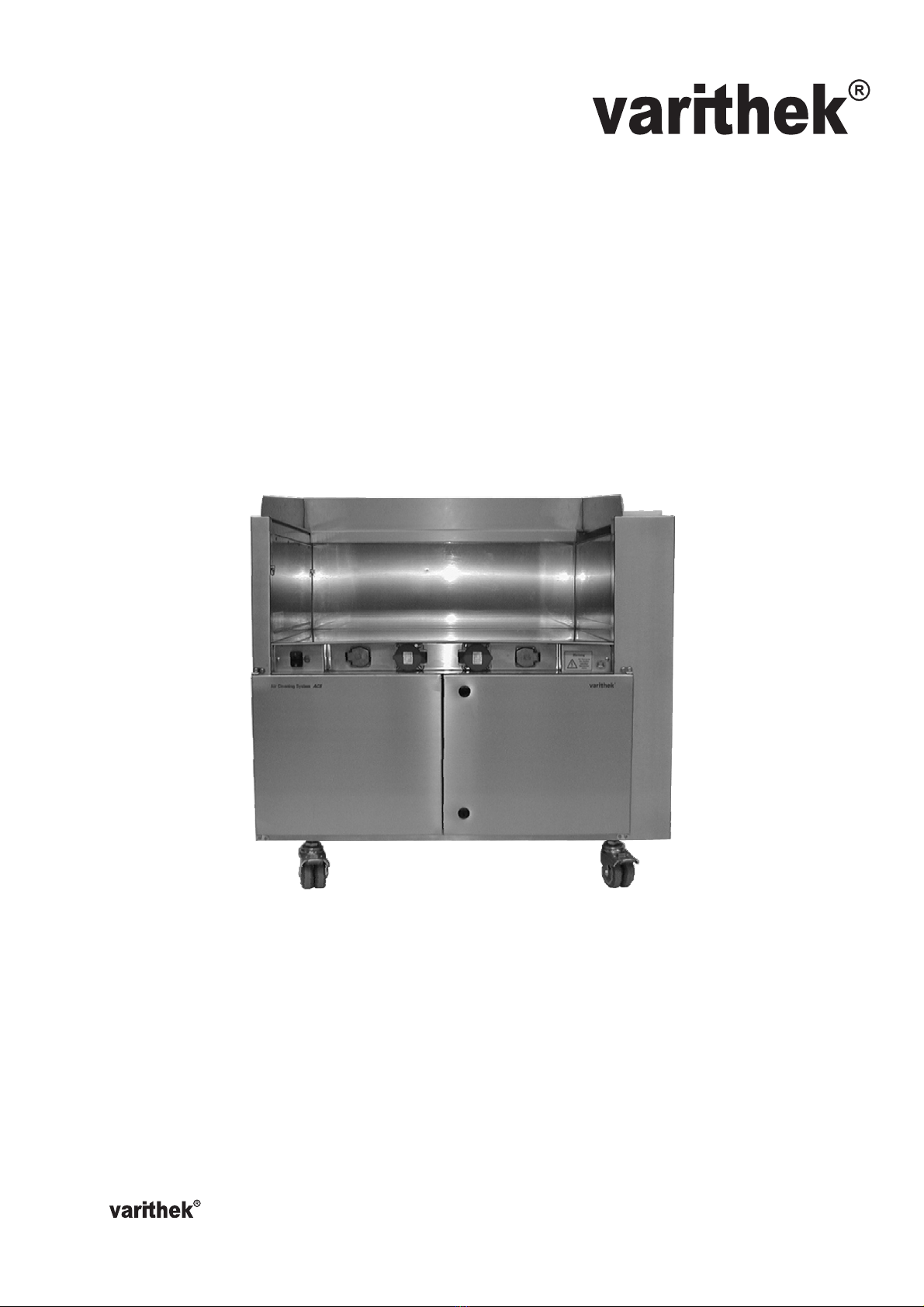
Air Cleaning System ACS
Operating Instructions
Please read carefully before use
- Eisfink and RieberThe product innovation from
Type: acs 600 EasyClean, 800 EasyClean, 1000 EasyClean
Fig.: varithek acs 1000 EasyClean
®

Page 2
Air Cleaning System ACS
The Air Cleaning System ACS has been declared in accordance with guidelines 89/336 and
73/23/EWG, Low-Voltage. The respective documents are on file with the manufacturer.
Technical modifications reserved!
Due to constant development, illustrations, functional steps and technical specifications may differ
slightly.
Manufacturer’s address
EISFINK MAX MAIER GMBH & CO.KG
Im Werkzentrum Weststadt
Rheinlandstr. 11
D 71636 Ludwigsburg
Fon: +49/7141/479-0
Fax: +49/7141/479-299
http://www.eisfink.de or http://www.varithek.de
Information from: June 15, 2004

Page 3
Air Cleaning System ACS
Table of contents
1 General 4
1.1 Preliminary remarks 4
1.2 Symbols for user instructions 4
1.3 Laws, norms and guidelines 4
1.4 Contents of delivery 5
1.5 Instructions for the operator 5
1.6 Guaranty 5
2 Safety 6
2.1 Proper use 6
2.2 Improper use 6
3 Product description 7
3.1 Basic measurements and technical specifications 7
3.2 General equipment 7
3.3 Electrical equipment 8
3.4 varithek®functional cooking elements 8
4 Transport / Installation / Assembly 9
4.1 Mechanical 9
4.2 Electrical 9
5 Operation 10
5.1 General safety instructions 10
5.2 Putting the ACS into operation 10
5.3 Putting the varithek®functional cooking components into operation 11
6 Cleaning and Maintenance 12
6.1 General 12
6.2 Initial cleaning, routine cleaning and maintenance of the ACS module 12
6.3 Routine cleaning and maintenance of the varithek®functional cooking components 15
7 Switching off and taking breaks 16
8 Troubleshooting 17
9 Wiring Diagram 18
10 Line Diagram 19
Page 4
Air Cleaning System ACS
1 General
1.1 Preliminary remarks
The operating instructions were devised specifically for the Air Cleaning System ACS operating
personnel. They contain important instructions for assembling, installing, operating and cleaning
the system.
The operating instructions are valid for all available ACS modules and their variants.
The model type of the ACS module can be found in the delivery and ordering documents as well
as on the type plate.
Read the operating instructions carefully before initial operation and see to it that all users have
read these instructions before use. The operating instructions must always be available at the
place of operation.
1.2 Symbols for user instructions
Caution!
Designates a possibly dangerous situation. Failure to comply may lead to injuries and/or material
damage.
Caution! Hot Surface!
Designates a possibly dangerous situation involving hot surfaces. Failure to comply may lead to
burns and/or material damage.
Tip!
Designates user tips for optimal utilisation and provides other useful information.
1.3 Laws, norms and guidelines
Conception and manufacturing were conducted in compliance with requirements of the following
guidelines and regulations:
·Guideline 93/43/EWG: Hygiene Guideline
·Guidelines 89/336 and 73/23/EWG: Low-Voltage Guideline
·EN 60335-1: Safety of Electronic Appliances for Household Use and Conventional Purposes
·EN 60335-2-36 (in accordance)
·Draft EN 60335-2-99 (in accordance)
·TPS Test Programme for Large Kitchen Equipment: Ventilation Devices in Commercial Kitchens
(in accordance)

Page 5
Air Cleaning System ACS
1.4 Contents of delivery
·Contents of delivery and element type can be found in the respective enclosed delivery
documents.
·Remove the packaging from the elements and dispose of the packing material in an environment-
friendly and orderly manner.
·Check the elements for possible transport damage. Record any faults on the waybill of the carrier
and report them immediately to your supplier.
1.5 Instructions for the operator
As the operator you are responsible for:
·the proper operation as intended and directed of all elements of the Air Cleaning System,
·compliance with safety regulations and safety instructions,
·instructing the operating personnel and making them aware of the operating instructions,
·the proper functioning of existing safety devices,
·providing adequate protective and work clothing and
·suitable operating conditions.
1.6 Guaranty
As a general principle, EISFINK’s “terms of business” are effective. Details of the guaranty are regulated
therein.
The guaranty only covers appliances used as directed (see following chapter “Safety”).

Page 6
Air Cleaning System ACS
2 Safety
2.1 Proper use
The Air Cleaning System ACS is an extractor system, which, in combination with adequate and fitting
cooking appliances (e.g. varithek®functional cooking components), serves to remove cooking fumes and
vapours wherever it is set up. For proper use of the fitted cooking elements, consult the respective
operating instructions.
The Air Cleaning system does not replace kitchen ventilation equipment according to VDI 2052.
The following functions can be carried out in the ACS:
·frying, grilling on a grill surface or in a pan,
·cooking, wokking in pots and woks,
·deep-frying, frying dough in deep fryers and specialised dough-frying appliances.
Any other use is improper and may have unforeseen consequences.
2.2 Improper use
Improper and dangerous are particularly:
·flambéing,
·gas cooking appliances,
·transporting persons on mobile ACS-modules,
·using the fitted cooking appliances to heat rooms or anything other than food.
Caution!
Never leave the appliance unattended when in use.
The safety and operating instructions contained here do not supersede the observance of legal
and trade association regulations (e.g. ZH1/37 – Safety Instructions for Kitchens). These are to
be observed irrespective of all the directions listed here.
Page 7
Air Cleaning System ACS
3 Product description
The Air Cleaning System ACS is an extractor system, which, in combination with adequate and fitting
cooking appliances (e.g. varithek®functional cooking components), serves to remove cooking fumes and
vapours wherever it is set up. For proper use of the fitted cooking elements, see the respective operating
instructions.
The user can flexibly react to special requirements and wishes by transposing elements.
3.1 Basic measurements and technical specifications
Measurements/Model ACS 1000ec ACS 800ec ACS 600ec
Width 1000 mm 800 mm 600 mm
Depth with door(s) closed 720 mm 720 mm 720 mm
Depth with door(s) opened 1160 mm 1160 mm 1160 mm
Total height with splashguard 1000 mm 1000 mm 1000 mm
Height without splashguard 900 mm 900 mm 900 mm
Body height w/o wheels or splashguard 790 mm 790 mm 790 mm
Power supply 3N AC 400 V, 50 Hz, 16 amp., max. 11 kW
Power connection 2 m cable, 400 V, 16 amp., CEE-plug
IP-degree of protection IP 40 IP 40 IP 40
Weight : 140 kg 125 kg 110 kg
3.2 General equipment
ACS models: free-standing appliance as a:
·mobile version: equipped with 4 castor wheels, wheel diameter 75 mm. The castors on the
operational side have absolute locks.
·stationary version: equipped with 4 height-adjustable feet.
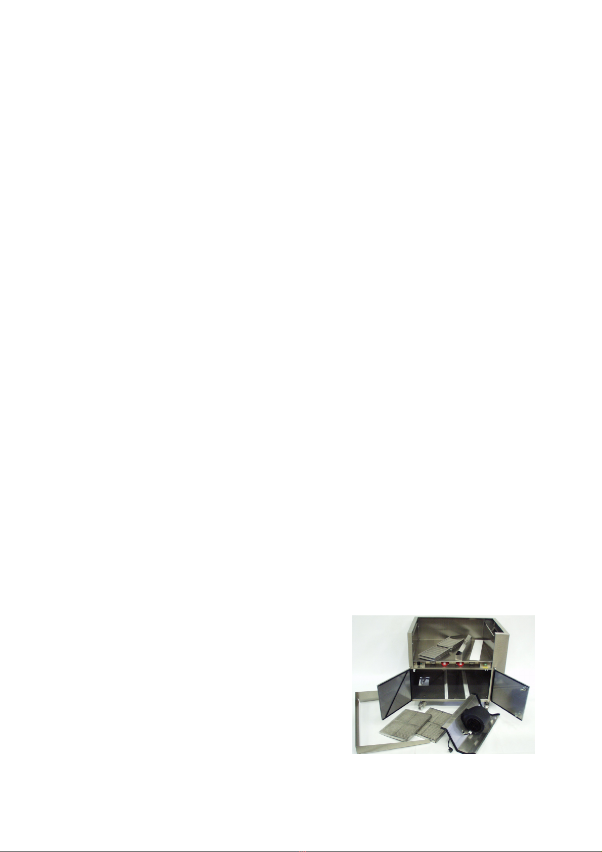
Standard features and parts:
The ACS module comes standard with four castor wheels; the two on the operational side have absolute
locks. Also included are one removable splashguard made of chromium-nickel steel CNS 18/10 (Material
# 1.4301), an E-cyclone eddy current filter made of CNS 18/10, a grease drip pan, a fan motor unit, a
double deodorising filter cassette with zeolite filling and a wrench.
1: Body made of CNS 18/10 with built-in
control panel and hinged bay interior side
and inspection doors
2: E-cyclone eddy current filter
3: Grease drip pan
4: Fan motor unit with power supply
cable and shrouded contact plug.
5: Double deodorising filter cassette
(2 pieces)
6: Cutting board, Hygenia white
7: Removable splashguard attachment
5
4
3
2
1
6
7

Page 8
Air Cleaning System ACS
3.3 Electrical equipment
Model Number of sockets
ACS 1000ec 2 x 230 V earthing-contact plugs
2 x 400 V CEE-plugs
ACS 600ec, 800ec 1 x 230 V earthing-contact plugs
1 x 400 V CEE-plugs
Power consumers Power input
Fan motor unit max. 230 V ACS 800,1000: 440 W ACS 600: 330 W
varithek®grill surface gp 3500 (hv) max. 230 V 3.5 kW (for use in ACS 600ec, 800ec, 1000ec)
varithek®deep grill surface gp-b 3500 max. 230 V 3.5 kW (for use in ACS 600ec, 800ec, 1000ec)
varithek®induction cooking surf. ik 3500 max. 230 V 3.5 kW (for use in ACS 600ec, 800ec, 1000ec)
varithek®induction cooking surf. ik 5000 max. 400 V 5.0 kW (for use in ACS 600ec, 800ec, 1000ec)
varithek®Ceran®cooking surf. ck 3400 max. 230 V 3.4 kW (for use in ACS 600ec, 800ec, 1000ec)
varithek®grill surface gp 5500 (hv) max. 400 V 5.2 kW (for use in ACS 600ec, 800ec, 1000ec)
varithek®grill surface gp 9000 (hv) max. 400 V 6.6 kW (for use in ACS 800ec, 1000ec)
varithek®grill surface gp 11000 (hv) max. 400 V 10.4 kW (for use in ACS 1000ec)
3.4 varithek®functional cooking elements
Element Purpose
Grill surfaces 1/1-gp 3500 for grilling and frying
400-gp 5500 (hv)
600-gp 9000 (hv)
800-gp 11000 (hv)
Deep grill surfaces 1/1-gp-b 3500 for grilling and frying in juice
Induction cooking surfaces ik 3500 for cooking and frying with induction energy

Page 9
Air Cleaning System ACS
4 Transport / Installation / Assembly
The valid electrotechnical, fire prevention and local Surveyor’s Office regulations are to be observed
during assembly and installation. Competent installation, operation and maintenance in compliance with
these instructions are necessary in order to provide a trouble-free function and operating safety of the
appliance.
Caution! Material damage possible!
When changing the location of the ACS module, the locks on the castors must be released. All
electrical couplings and any mechanical fastenings to surrounding furniture must also be
released. Always make sure that the power-supply cable is secured in such a way (adhesive
tape), that it cannot get caught under the wheels.
4.1 Mechanical
Bring the ACS module to the planned location, which must be level and clean.
Be careful not to roll over any objects lying on or sticking out of the floor when transporting the
ACS module. They could cause damage to the power-supply cable on the bottom of the
appliance.
Also make sure that the extractor module is “horizontal”. The attached castors are height-adjustable for
this purpose. You can adjust the castors by releasing the lock nut with the enclosed wrench, then turning
the axle of the respective castor with the wrench. To lower the extractor module, turn clockwise; to raise
the extractor module, turn counterclockwise.
Use a level to be sure. As soon as the correct height is reached, lock the position by tightening the lock
nut with the enclosed wrench.
To lock the appliance in place, lock the wheels on the operational side by stepping on the wheel locks.
4.2 Electrical
Before operating, check the line voltage and type of current. They must comply with the specifications on
the type plate.
The DIN / VDE 0100 ff. regulations and the technical connection conditions of the electricity-supplying
company must be observed.
The unit is equipped with a power supply cable with a CEE-plug to connect to a wall socket. Make sure
the 400 V / 16 amp. CEE-socket is fused. Please note that the appliances may be damaged in the event
of a neutral interruption. The socket must be easily accessible, so that the unit can be unplugged at any
time. As a protection class one appliance, it must always be connected to the protective conductor. The
cable is to be placed where there is no chance of it being crushed.
If there are any uncertainties, consult an electrical technician.
If the lead wire of this appliance is damaged, it must be replaced by the manufacturer, an authorised
service center or a similarly qualified person in order to avoid danger.

Page 10
Air Cleaning System ACS
5. Operation
5.1 General safety instructions
Caution! Danger of rolling over and tipping!
When rolling the ACS module over uneven surfaces, you should be prepared for uncontrolled
drifting. Do not let go of the module or let it roll by itself.
Caution! Danger of being crushed!
When changing the location it is important that no body parts come between the ACS module and
any surrounding furniture, especially when rolling it into a recess. After putting the module into
position, the castors must be locked to avoid any rolling.
5.2 Putting the ACS into operation
The function of the extractor module was checked after production. Prior to the initial use, please make
sure that no traces of packaging or any other objects have found their way into the housing interior or the
side air canals and that the filter and grease drip pan have been fitted correctly
The ACS module is never to be operated without the correctly fitted and correctly placed filter
components or without the grease drip pan.
The extractor module is put into operation by inserting the power supply cable into a properly installed and
fused 400 V CEE-socket. As soon as the connection is made, the indicator light (1) lights up in green.
From this point on, the sockets built into the control panel are receiving power.
To start the ventilation system, the on/off switch for the ventilation system must also be turned on. Once
the ventilation system is turned on, a curtain of air blown over the working area guides the greasy,
odorous vapours from the left of the operational side to the right into the suction canal and the filter
system.
We recommend leaving the ventilation system on for an additional 10 minutes after cooking, so
that the vapours rising from the remaining heat are not able to spread into the surroundings.
No objects or food may enter the air canals (exhaust slit and suction canal) or the curtain
of air.
Before opening the door(s) of the ACS module, the on/off switch for the ventilation system must
be switched off. Otherwise, the fan in the ventilation unit may cause injury.
Operating panel
1: On/off switch for
ventilation system
2: Indicator lamp
3: 230 V earthing-contact
plug (ACS 1000ec has 2)
4: 400 V CEE plug
(ACS 1000ec has 2)
1 2 3 4

Page 11
Air Cleaning System ACS
5.3 Putting the varithek®functional cooking components into operation
Make sure that the left interior side of the bay has been properly locked to the sides of the housing using
the turning knobs.
When using varithek®functional cooking components, first fit the basic unit into the bay of the extractor
module.
Then fit the varithek®cooking appliance into the basic unit.
Caution! Danger of being crushed!
There is a danger of crushing body parts when fitting the cooking appliance. Also make sure that
the electrical cables of the varithek®functional elements are not crushed!
Please make sure that the varithek®basic units and functional components are placed in the
correct order: the higher appliance should always be placed to the left on the operational side
(exhaust side).
Example fittings of the ACS 1000 with varithek®functional components
Functional elements in basic unit Placement in ACS 1000
2 x grill surfaces gp 3500 (hv), 230 V 2 x AST 255 (high) 1 x left, 1 x right
2 x deep grill surfaces gp-b 3500, 230 V 2 x AST 255 (high) 1 x left, 1 x right
1 x grill surface gp 3500 (hv), 230 V,
1 x deep grill surface gp-b 3500, 230 V 2 x AST 255 (high) gp 3500 left, gp-b 3500 right
2 x induction cooking surfaces ik 3500, 230 V 2 x AST 155 (low) 1 x left, 1 x right
2 x induction cooking surfaces ik 5000, 400 V 2 x AST 155 (low) 1 x left, 1 x right
1 x grill surface gp 3500 (hv), 1 x induction 1x AST 255 (high) gp 3500 left,
cooking surface ik 3500, 230 V 1x AST 155 (low) ik 3500 right
Follow the operating instructions valid for the varithek®functional components.
Caution! Danger of burns and being crushed!
When using cooking or grilling appliances or deep fryers, there is a danger of being burned or
injured on hot surfaces. This danger exists even after turning these appliances off, because the
heated surfaces may cool off very slowly.
Let the cooking appliances cool completely before starting to clean and remove the cooking
appliances as well as the ACS.
If you wish to change the location of the ACS module after use, please remove the fitted cooking
appliances or secure them from sliding.

Page 11a
Air Cleaning System ACS
Use the enclosed holding clamps to prevent varithek®grills and deep grills from sliding out of the
basic unit.
Deep fryer in the ACS Air Cleaning System
If a deep fryer FT 6 is to be used in the ACS 1000, the deep fryer must be inserted into a
varithek®countertop basic unit AST 255 and secured with an insert mask EM AST FT 6. In
principle, the basic rules for filters and grease maintenance should be observed in order to
prevent a reduction in the effectiveness of the filter systems.
The countertop basic unit with the deep fryer is to be placed on the right on the operational side,
close to the suction canal. We recommend operating a deep fryer solely in combination with
another deep fryer or grill.
Danger of explosion! Danger of burns!
Never pour water into the deep fryer, as long as it is filled with fat / oil – neither in hot nor in cold
working conditions.

Page 12
Air Cleaning System ACS
6 Cleaning and Maintenance
6.1 General
Cleaning is especially important for facilities and appliances in which food is prepared or offered for sale.
In order to maintain hygienic conditions, the operating personnel must master the chapter “Cleaning and
Maintenance”.
Caution! Danger of burns, cuts, and being crushed!
When cleaning the system, use gloves that are appropriate for cleaning; skin that is softened by
cleansing agents can be injured on metal edges.
Let the cooking appliances cool completely before starting to clean and remove the cooking
appliances as well as the ACS. (Grill approx. 30 min.)
Caution! Material damage!
Do not use any acidic cleansing agents. The cleansing agent may not contain any hydrochloric or
hydrofluoric acid, because these may lead to discoloration of the surfaces or even rust holes. Do
not use any sharp-edged cleaning instruments.
Warning!
The appliance must be unplugged before cleaning.
Cleansing agents
Clean the housing parts only with appropriate cleansing agents and a small amount of water. Use
the cleansing agents in accordance with the manufacturer’s instructions. Stubborn deposits should
be treated intensely, e.g. with a soft plastic fleece, then rinsed with fresh water..
6.2 Initial cleaning, routine cleaning and maintenance of the ACS module
The module should be cleaned before operating for the first time, to thoroughly remove any residues left
from manufacturing and assembly.
We recommend thoroughly cleaning the ACS module after every use.
The appliances must be unplugged before cleaning. Parts (plastic parts) that may be sensitive to
the cleansing agent should be protected. The splashguard and side cheek cover must first be
removed. The appliances in the bay may remain in place.
To clean the housing parts, use a soft cloth and a mild, grease-dissolving but non-abrasive cleansing
agent mixed with water. Grease deposits and grease-bound pigment stains are easily removed with all-
purpose cleanser, neutral cleanser or alkaline cleansing agents.
Solvent-based cleansing agents and non-abrasive emulsions help to remove very strong grease deposits
(resinified oils and fats) from housing parts.
The folding parts of the housing, the junctions of the elements as well as bottom lips and edges must be
cleaned very carefully. Bits of food and dirt can settle in these areas.

Page 13
Air Cleaning System ACS
The left side wall of the bay can be opened for cleaning. For this purpose, the varithek®basic units and
respective functional elements must be removed from the bay and securely stowed. The left side panel is
opened by turning the knobs counterclockwise and folding the side panel toward the middle of the
appliance. The inside of the air canal can subsequently be cleaned with conventional mild cleansers.
Cleaning the filter area
Make sure that the ACS module is unplugged from the power supply.
To clean the filter area, open the inspection doors by turning the locking knobs one-half turn
counterclockwise with a wide flat tip screwdriver.
Caution! Danger of injury!
Never open the doors of the extractor module while in operation. Danger of being injured by the
fan of the ventilation unit. Always unplug appliance from the power supply first. There is a danger
of fire if cleaning is not in compliance with the following instructions.
E-cyclone eddy current filter (grease separating filter) / grease drip pan
The eddy current filter is found in the right side cheek. It is removed by pulling the handle on top upwards
and can then be cleaned in the dishwasher. The cleaning interval depends on the intensity of use and the
degree of grease pollution – we recommend a daily cleaning. The same applies to the grease drip pan.
The grease filter and the grease drip pan are replaced after being cleaned and completely dried. Make
sure that both components fit perfectly in their respective recesses and that the handle on the filter is
pointing up.
Fan motor unit
The fan motor unit, located in the middle, is only to be removed for cleaning when it is very soiled, e.g., if
traces of grease are apparent on or around the fan housing. For this purpose the power supply cable plug
must be removed from the socket located above the ventilation unit. The fan can then be pulled forward
out of the plastic guide.
Caution!
It is imperative that water does not enter the fan motor during cleaning. When cleaning the interior
with water, remove the fan motor unit and seal the blue socket with the lid.
Double deodorising filter cassette (zeolite filter)
The zeolite-filter, located on the left side, serves to separate odours. Its effect depends on the type of
vapours and their grease ratio.
To always attain an optimal odour binding, we recommend cleaning (technical term: “desorbing”) the filter
after approx. 24 hours of operation, in any case at least twice a week.
This process can be repeated as necessary throughout the lifespan of the ACS module, when the effect
of the filter diminishes.

Page 14
Air Cleaning System ACS
The deodorising filter cassettes are cleaned or desorbed in an oven or hot-air steamer.
Remove the deodorising filter cassettes and place them in an oven or hot-air steamer. Desorption occurs
using only hot air (not steam) at approx. 220°C over a period of about one hour.
After desorption has occurred, the odorous substances are released from the filter and are contained in
the hot-air steamer / oven. Before opening the door, the extractor system above should thus be turned on
in order to extract the released odorous substances.
Caution! Danger of burns!
After heating the deodorising filter to 220°C, the filter components must be left to cool with the
door of the oven or hot-air steamer open, because they are extremely hot. To prevent burns,
please use special gloves to remove the deodorising filter!
Should the zeolite filter cassettes become covered in a greasy film, they may also be washed with water
and dishwashing detergent. In this case, the zeolite filter must be completely dried. The drying process
should be carried out in the oven or hot-air steamer as described above.
When cleaning is completed, the deodorising filters are replaced in the ACS module and the door is
locked. To do this, turn both locking knobs one-half turn clockwise.
Caution! Danger of being crushed!
Make sure that no electric cable is pinched between the doors and housing and that the door
gaskets lie neatly on the body.
If you wish to wash the entire inner compartment of the module after completely removing all filter
components, the grease drip pan and the fan motor unit, first seal the socket for the ventilation
connection with the blue lid.
Make sure that the bottom opening to the left of the zeolite filter is not shifted or (even partly)
covered, because that would influence the air speed on the exhaust side. This opening was
adjusted correctly at the plant.
Any change to the bottom opening has a negative effect on the function of the ventilation system and the
development of odours.

Page 15
Air Cleaning System ACS
6.3 Routine cleaning and maintenance of the varithek®functional cooking components
The respective operating instructions must be followed, in particular the instructions about
cleaning and maintenance.
Caution! Danger of burns, cuts, and being crushed!
When cleaning the system, use gloves that are appropriate for cleaning; skin that is softened by
cleansing agents can be injured on metal edges.
Let the fitted cooking appliances cool completely before starting to clean and remove the cooking
appliances as well as the ACS.
Here are a few exemplary extracts:
varithek®basic unit
If subject to strong vapours, the varithek®basic unit(s) should be cleaned after every use.
varithek®grills / deep grills
These appliances are to be cleaned after every use.
To clean the grill surface, use a grill surface cleaning blade to remove coarse, stuck-on deposits. Then
use a cleaning sponge with a rough surface and a grease-dissolving cleansing agent for the fine cleaning.
Rinse thoroughly with fresh water after cleaning to make sure that no cleansing agent residue is left on
the grill surface. Guide the water out through the grease drain opening found in the grill surface after
checking that the grease drip pan is in place.
varithek®grills / deep grills with hard-chromed grill surface
Cleaning proceeds as above, except that no cleaning blade may be used.
Caution! Material damage!
Sharp-edged objects damage the hard-chromed surface.
varithek®induction and Ceran®hobs
Use a special Ceran®glass cleaner and a soft cloth to clean the Ceran®glass. A Ceran®glass cleaning
blade may also be used to remove coarse deposits.
To completely remove cleansing agent residue, wipe with a moist soft cloth and water until no more
residue can be seen.
Caution! Material damage!
Do not use any sharp-edged objects to clean the Ceran®glass, as they scratch the Ceran®glass.

Page 16
Air Cleaning System ACS
7 Switching off and taking breaks
Before turning off the ACS module for a longer period of time, pull the power supply cable out of the
socket. This disconnects all the electrically connected functional elements from the power supply. The
ACS module is switched off.
Caution!
Aside from the ACS module, all fitted functional cooking elements are to be turned off separately
after every use.
Caution! Danger of burns!
The fitted cooking elements maintain their heat for a while after being switched off, so that even
then there is a danger of being burned.
A grill requires, for example, about 30 minutes to cool down.
Caution! Danger of being crushed!
Secure the module as well as the fitted cooking functions from sliding.
Caution! Presence of children in the hazard area!
Make sure that no children are present in the vicinity of the module or the functional cooking
elements or playing with the appliances.

Page 17
Air Cleaning System ACS
8 Troubleshooting
Check the ventilation system equipment for damage at least every 6 months.
If there are any disturbances, the ACS module is to be separated from the mains by unplugging it.
Repairs to the ACS module as well as to the utilised functional cooking elements may only be carried out
by an authorised service center.
Attention!
Should anyone who is not a service technician authorised by the manufacturer attempt any repairs
to the housing or appliance technology, the guaranty becomes immediately void, irrespective of
the respective manufacturer.
For any faults not caused by deposits and inadequate cleaning, we recommend contacting your supplier,
who will give you the address of a suitable authorised service center.
Attention!
Only original parts of the respective manufacturer may be used for repairs.
If the lead wire of the ACS module or the utilised cooking function is damaged, the appliance may
not be used and must not be re-connected to the mains until the manufacturer or authorised
service center has replaced the cable with an original part.
Problem Possible cause Remedy
plug connections interrupted check if plugs are connected
damaged cable contact service center
no power supply
to ACS module
module not plugged in plug the module in
appliances not plugged in plug them incooking appliances
don’t work defective appliance contact service center
no exhaust current exhaust opening clogged,
covered, or blocked. Observe
positioning height of 260mm.
remove blockage
temperature of cooking
appliances set too high
reduce temperature to max. 230° Cheavy smoke and odour
development
filter components clogged clean filters
module difficult to move castor locks are on release locks
Manufacturer’s address
EISFINK MAX MAIER GMBH & CO.KG
Im Werkzentrum Weststadt
Rheinlandstr. 11
D 71636 Ludwigsburg
Fon: +49/7141/479-0
Fax: +49/7141/479-299
Seite 18
Air Cleaning System ACS
9 line diagram ACS 600ec, 800ec, 1000ec
ACS 600ec
ACS 800ec
Seite 19
Air Cleaning System ACS
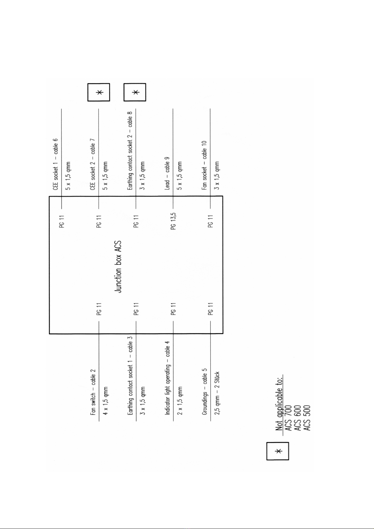
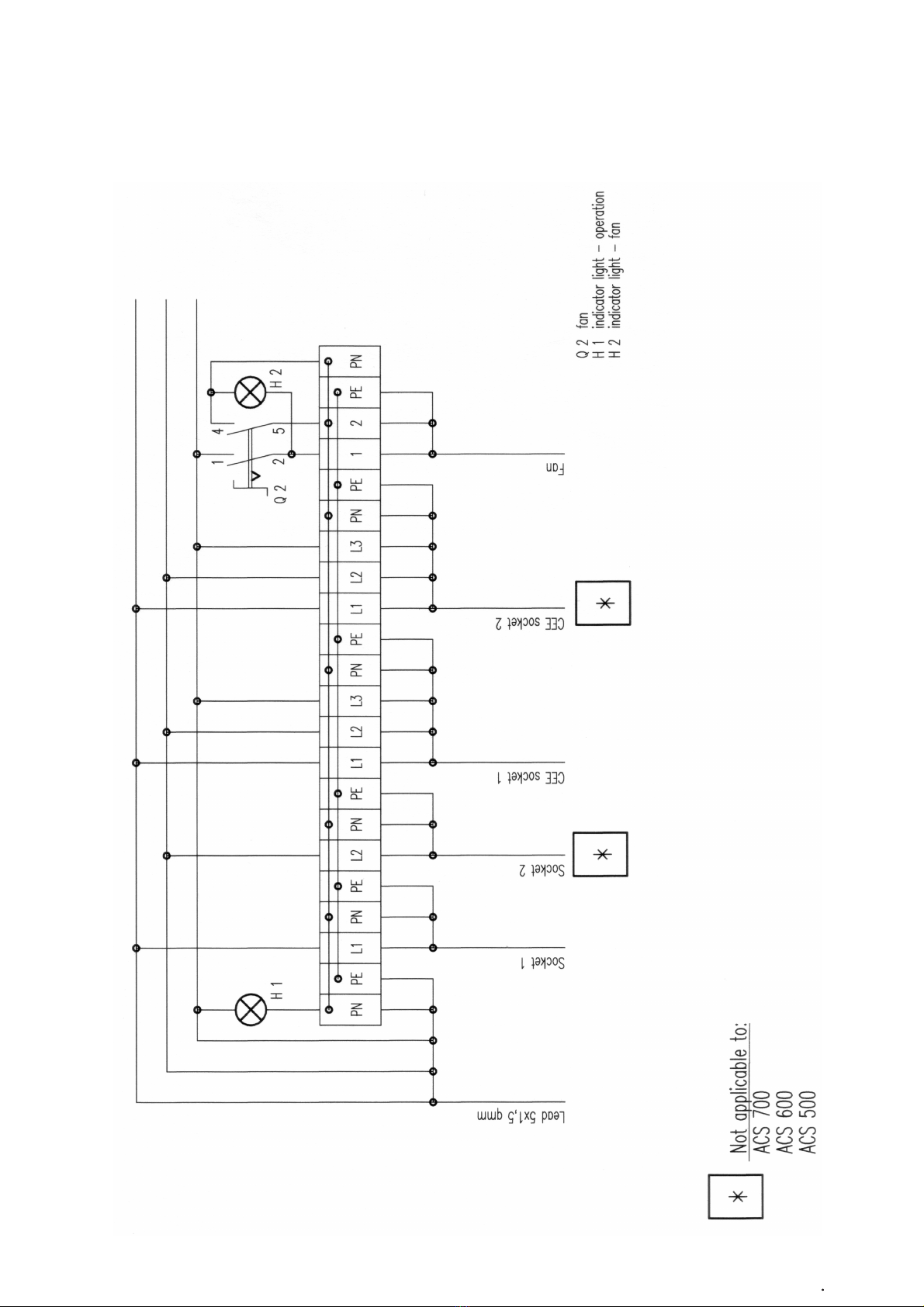
10 wiring diagram ACS 600ec, 800ec, 1000ec
ACS 600ec
ACS 800ec
This manual suits for next models
2
Table of contents
Other eisfink Air Cleaner manuals


