Ekckom XC8602JE User manual

2013.
2013.6
6(
(Version
Version 1
1)
)
XC8602JE
Optical Receiver
Manual

XC
XCXC8602JE
8602JE8602JE Optical
OpticalOptical Receiver
ReceiverReceiver Manual
ManualManual
- 1 -
1. Product Summary
XC8602JE outdoor optical receiver is our latest 1GHz optical receiver. With wide range
receiving optical power, high output level, low power consumption and compact structure, easy to
install. It is the ideal equipment to build the high-performance NGB network.
2. Performance Characteristics
■Adopt advanced optical AGC technique, optical AGC control range: +2dBm ~-9/-8/-7dBm
adjustable;
■Forward working frequency extended to 1GHz, RF amplifier part adopts the high performance
low power consumption GaAs chip, the maximum output level up to 116dBμV;
■EQ and ATT both use the professional electric control circuit, make the control more accurate,
operation more convenient;
■Built-in the Ethernet responder, support remote network management (optional);
■The optical output port and network management interface are external or internal (optional);
■Built-in high reliability low power consumption power supply;
3. Technique Parameter
Item Unit Technique Parameters
Optical Parameters
Receiving Optical Power dBm -9 ~ +2
Optical Return Loss dB >45
Optical Receiving
Wavelength nm 1100 ~ 1600
Optical Connector Type SC/APC or specified by the user
Fiber Type Single mode
Link Performance
C/N dB ≥ 51 EQ 6dB, Output level 108 dBμV
(FZ110)
42-channel signal source input,
-2dBm optical power received
C/CTB dB ≥ 67
C/CSO dB ≥ 62
RF Parameters
Frequency Range MHz 45 ~1003 45 ~862
Flatness in Band dB ±0.75
Rated Output Level dBμV ≥ 108
Max Output Level dBμV ≥ 112 (-9 ~ +2dBm Optical power receiving)
≥ 116 (-7 ~ +2dBm Optical power receiving)
Output Return Loss dB ≥16
Output Impedance Ω 75
Optical AGC Range dBm (-9dBm/-8dBm/-7dBm)—(+2dBm) adjustable
Electrical control EQ range dB 0~15
Electrical control ATT range dB 0~15
XC
XCXC8602JE
8602JE8602JE Optical
OpticalOptical Receiver
ReceiverReceiver Manual
ManualManual
- 2 -
General Characteristics
Power Voltage V A: AC (150~265) V B: AC (35~90) V
Operating Temperature ℃-40~60
Consumption VA ≤14
Dimension mm 220(L)* 205(W)* 65(H)
Note: The forward RF indexes above are tested when adopt NEC module. Use other module, the indexes will be a
little different.
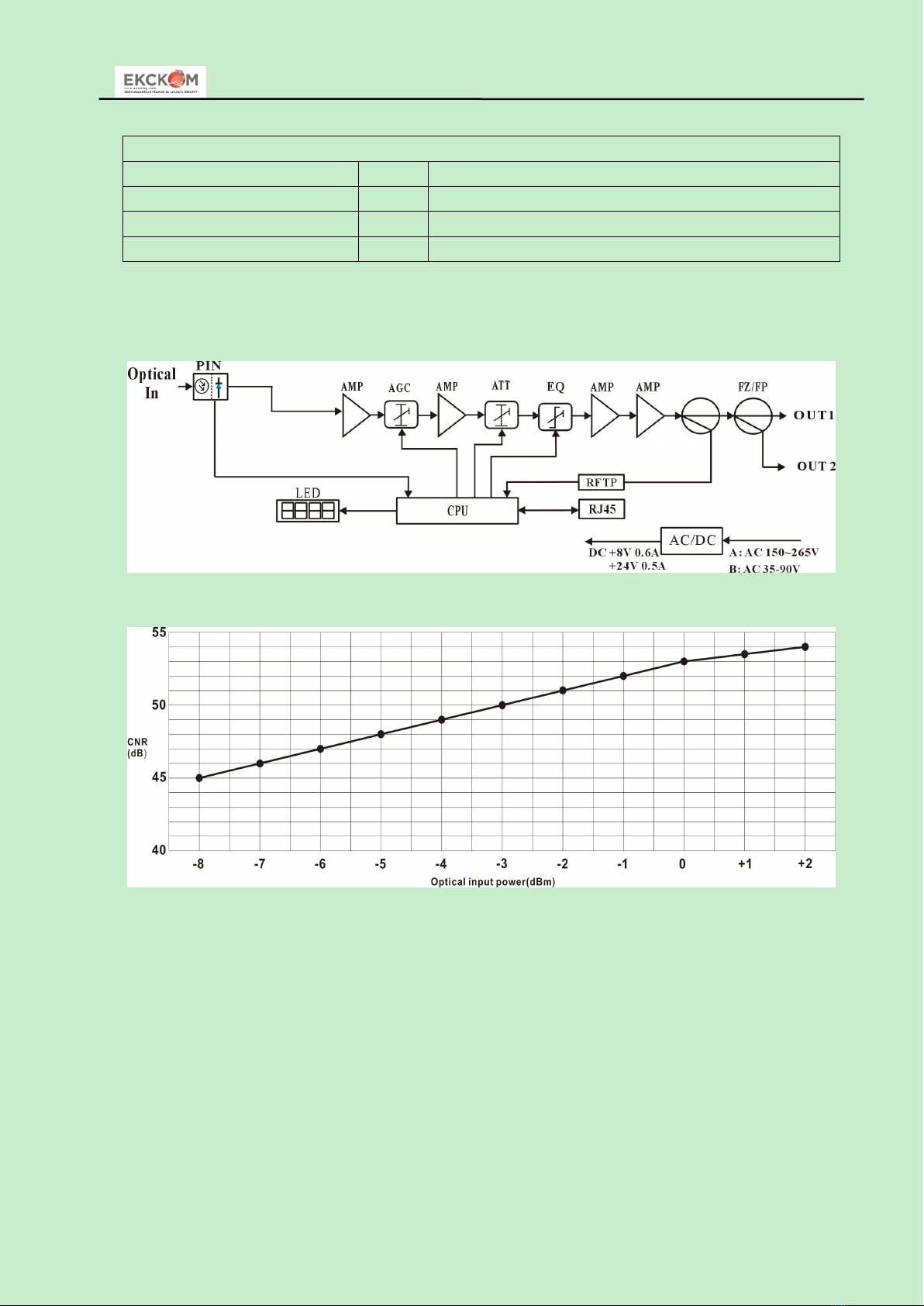
4. Block Diagram
5. Relation Table of Input Optical Power and CNR
XC
XCXC8602JE
8602JE8602JE Optical
OpticalOptical Receiver
ReceiverReceiver Manual
ManualManual
- 3 -
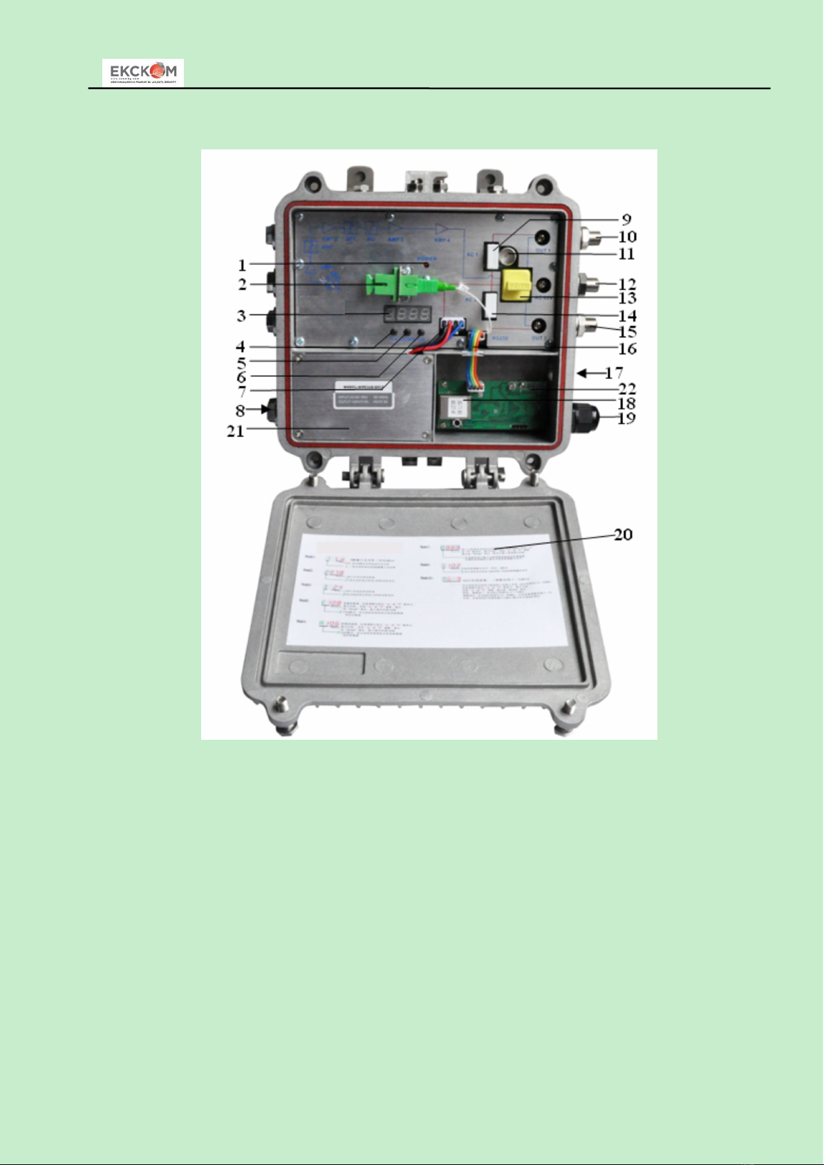
6. Structure Description
1. Working indicator 2. Optical receiving port
(or external, optional)
3. LED digital display tube
4. Enter key 5. Down key 6. Up key
7. Power Interface 8. AC220V input port
(when AC220V power supply)
9. AC60V power-pass inserter port
10. OUT1 11. -20dB test port 12. AC60V feed port
13. FZ110 or FP204 14. AC60V power-pass inserter port 15. OUT 2
16. Transponder connecting wire 17. Optical fiber access port 18. RJ45 interface (or external, optional)
19. Network cable in 20. Operating instruction 21. Switching power supply
22. Transponder
XC
XCXC8602JE
8602JE8602JE Optical
OpticalOptical Receiver
ReceiverReceiver Manual
ManualManual
- 4 -
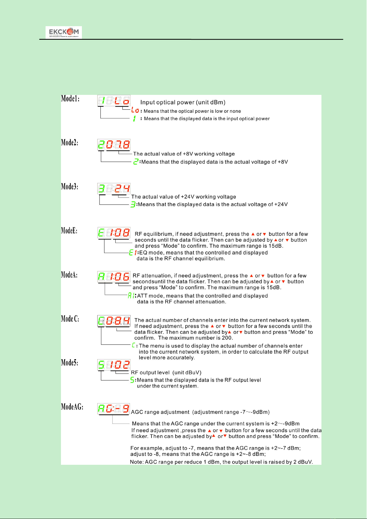
7. Function Display and Operating Instruction
Mode: Mode selection button, total twelve modes, press the mode selection button to enter the
corresponding status display, twelve modes to cycle.
The following is the detailed instructions:
XC
XCXC8602JE
8602JE8602JE Optical
OpticalOptical Receiver
ReceiverReceiver Manual
ManualManual
- 5 -
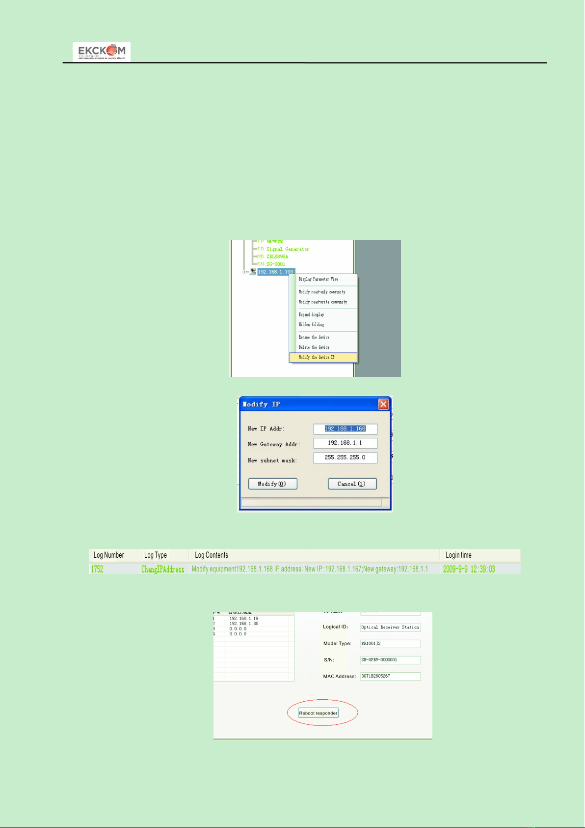
8. NMS setup instructions
If users configured the network management responder, need to do the following settings:
Responder IP setup instruction:
Network management directly modify:
1. Default IP is 192.168.1.168 ,default gateway is 192.168.1.1 ,default subnet mask is
255.255.255.0
2. Connect the computer and responder (can be direct connected), and change the computer
IP to 192.168.1.XXX (XXX is any number from 0 to 255 except 168); start upper computer
network management software, then search the device and log in.
3. Right-click device icon and choose modify the device IP.
4. Enter new IP address, gateway and subnet mask.
5. Click modify ,then exit, it is done. There will show new IP address and gateway on
operational logbook.
6. Reboot the responder, the new IP take effect (Click the reboot button in the network
management software or power on again)

XC
XCXC8602JE
8602JE8602JE Optical
OpticalOptical Receiver
ReceiverReceiver Manual
ManualManual
- 6 -
9. Common Failure Analysis and Troubleshooting
Failure phenomenon Failure cause Solution
After connecting the
network, the image of the
optical contact point has
obvious netlike curve or
large particles highlights
but the image background
is clean.
1. The input optical power of the
optical receiver is too high, make the
output level of the optical receiver
module too high and RF signal index
deteriorate.
2. The RF signal (input the optical
transmitter) index is poor.
1. Check the input optical power and make
appropriate adjustments to make it in the
specified range; or adjust the attenuation of
optical receiver to reduce the output level and
improve index.
2. Check the front end machine room optical
transmitter RF signal index and make
appropriate adjustments.
After connecting the
network, the image of the
optical contact point has
obvious noises.
1. The input optical power of the
optical receiver is not high enough,
results in the decrease of C/N.
2. The optical fiber active connector
or adapter of the optical receiver has
been polluted.
3. The RF signal level input the
optical transmitter is too low, make
modulation degree of the laser is not
enough.
4. The C/N index of system link
signal is too low.
1. Check the received optical power of the
optical contact point and make appropriate
adjustments to make it in the specified range.
2. Recover the received optical power of the
optical contact point by cleaning the optical
fiber connector or adapter etc methods.
Specific operation methods see “Clean and
maintenance method of the optical fiber
active connector”.
3. Check the RF signal level input the optical
transmitter and adjust to the required input
range. (When the input channels number less
than 15, should higher than nominal value.)
4. Use a spectrum analyzer to check the
system link C/N and make appropriate
adjustments. Make sure the system link signal
C/N﹥51dB.
After connecting the
network, the images of
several optical contact
points randomly appear
obvious noises or bright
traces.
The optical contact point has open
circuit signal interference or strong
interference signal intrusion.
1. Check if there is strong interference signal
source; change the optical contact point
location if possible to avoid the influence of
strong interference signal source.
2. Check the cable lines of the optical contact
point, if there is shielding net or situation that
the RF connector shielding effect is not good.
3. Tightly closed the equipment enclosure to
ensure the shielding effect; if possible add
shielding cover to the optical contact point
and reliable grounding.
After connecting the
network, the images of
several optical contact
points appear one or two
horizontal bright traces.
Power supply AC ripple interference
because of the bad earth of equipment
or power supply.
Check grounding situation of the equipment,
make sure that every equipment in the line
has been reliably grounding and the
grounding resistance must be﹤4Ω.

XC
XCXC8602JE
8602JE8602JE Optical
OpticalOptical Receiver
ReceiverReceiver Manual
ManualManual
- 7 -
After connecting the
network, the received
optical power of the optical
contact point is unstable
and has large continuous
change. The output RF
signal is unstable, too. But
the detected output optical
power of the optical
transmitter is normal.
The optical fiber active connector
types do not match, maybe the APC
type connect to PC type, make the
optical signal cannot normal
transmission.
The optical fiber active connector or
adapter may be polluted seriously or
the adapter has been damaged.
1. Check the type of optical fiber active
connector and adopt the APC type optical
fiber active connector to ensure the normal
transmission of optical signal.
2. Clean the polluted optical fiber active
connector or adapter. Specific operation
methods see “Clean and maintenance method
of the optical fiber active connector”.
3. Replace the damaged adapter.
10. Clean and maintenance method of the optical fiber active connector
In many times, we consider the decline of the optical power as the equipment faults, but
actually it may be caused by that the optical fiber connector was polluted by dust or dirt. Inspect the
fiber connector, component, or bulkhead with a fiberscope. If the connector is dirty, clean it with a
cleaning technique following these steps:
1. Turn off the device power supply and carefully pull off the optical fiber connector from the
adapter.
2. Wash carefully with good quality lens wiping paper and medical absorbent alcohol cotton. If
use the medical absorbent alcohol cotton, still need to wait 1~2 minutes after wash, let the
connector surface dry in the air.
3. Cleaned optical connector should be connected to optical power meter to measure output
optical power to affirm whether it has been cleaned up.
4. When connect the cleaned optical connector back to adapter, should notice to make force
appropriate to avoid china tube in the adapter crack.
5. The optical fiber connector should be cleaned in pairs. If optical power is on the low side after
clean, the adapter may be polluted, clean it. (Note: Adapter should be carefully operated, so as
to avoid hurting inside fiber.
6. Use compressed air or degrease alcohol cotton to wash the adapter carefully. When use
compressed air, the muzzle aims at china tube of the adapter, clean the china tube with
compressed air. When use degrease alcohol cotton, insert directions need be consistent,
otherwise can’t reach a good clean effect.
Table of contents
Other Ekckom Receiver manuals


