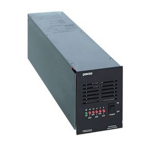
Paso PM2092-V User manual

1- PMS2000 System -
INTRODUZIONE
Nel ringraziarVi per aver scelto un prodotto
PASO, vogliamo ricordarVi che la nostra
azienda opera con sistema di qualità certificato.
Tutti i nostri prodotti vengono pertanto
controllati in ogni fase della produzione per
garantirVi la piena soddisfazione del Vostro
acquisto. Per ogni evenienza la garanzia
coprirà, nel periodo di validità, eventuali difetti
di fabbricazione. Vi raccomandiamo di leggere
attentamente le seguenti istruzioni d’uso per
sfruttare appieno le prestazioni offerte da
questo prodotto e per evitare eventuali
problemi.
INTRODUCTION
While thanking you for having chosen a PASO
product, we would like to remind you that our
company works according to a certified Quality
System. This means that all our products are
checked during every phase of manufacturing
in order to ensure that you will be fully satisfied
with your purchase. In any case, the guarantee
will cover any manufacturing flaws during the
guarantee period. We recommend that you
read the following instructions for use and
follow them carefully in order to exploit in full
the performance of this product and use it
correctly.
NOTA
Nel continuo intento di migliorare i propri prodotti,
la PASO S.p.A. si riserva il diritto di apportare
modifiche ai disegni e alle caratteristiche tecniche
in qualsiasi momento e senza alcun preavviso.
NOTE
PASO S.p.A. strive to improve their products
continuously, and therefore reserve the right to
make changes to the drawings and technical
specifications at any time and without notice.
SISTEMA MODULARE PROFESSIONALE PMS2000
PMS2000 PROFESSIONAL MODULAR SYSTEM
VES
Scheda di controllo amplificatore
Amplifier control card PM2092-V
Istruzioni per l’uso
Instructions for use
Manuel d'utilisation
Gebrauchsanleitung
Gebruiksaanwijzing
Instrucciones de empleo
Carte de contrôle amplificateur
Verstärkerkontrolleinheit
Besturingskaart versterker
Tarjeta de control amplificador

- PMS2000 System -
Ref. 11/596 PM2092-V
2
1. DESCRIZIONE GENERALE
La scheda di controllo PM2092-V è stata creata
per consentire l'esecuzione semplice e veloce di
test sugli amplificatori modulari PMWxx(1)e per
verificare l’integrità della/e linea/e altoparlanti
tramite l’utilizzo delle schede PM2094-V.
Questa scheda gestisce tutte le funzioni
dell'amplificatore, dagli ingressi alla diagnostica
ed è in grado di eseguire le seguenti funzioni:
• misure di impedenza di linea;
• diagnostica dell'amplificatore;
• verifica dell’integrità della linea altoparlanti
(PM2094-V).
• verifica isolamento di terra (GND FAULT);
• controllo di volume;
• selezione di due ingressi;
• controllo del relè di potenza;
• possibilità di inserimento del filtro LOW CUT;
• funzionamento in modalità di risparmio
energetico ‘LOW POWER’.
La scheda può inoltre essere controllata tramite
interfaccia seriale. Oltre ad eseguire tutte le
operazioni e/o verifiche impostate localmente con
i dip-switches, sarà possibile visualizzare e
modificare tutti i parametri tra cui:
• lettura dell'impedenza di riferimento per il test;
• valore minimo e massimo entro cui il test risulta
valido;
• lettura dello stato dei test;
• test dell'ingresso;
• misura della temperatura dei transistor finali;
• regolazione del volume;
• comando remoto del relè.
(1) Nel modello PMW500-V la scheda è integrata
all’interno dell’apparecchio.
(2) Procedura valida per i modelli PMW60, PMW120
e PMW240.
1.1 Installazione(2)
Il funzionamento dell'amplificatore con la scheda
di controllo PM2092-V installata sarà legato al
funzionamento della scheda stessa. Attenersi, per
l’installazione della scheda di controllo, alla
seguente procedura:
1. assicurarsi che l'apparecchio sia disconnesso
dalla rete;
2. rimuovere il pannello laterale sinistro
dell'amplificatore;
1. GENERAL DESCRIPTION
The PM2092-V control card was created to
provide a simple and rapid way of testing the
PMWxx(1)modular amplifiers and for checking the
integrity of the loudspeaker line(s) using the
PM2094-V cards.
This card manages all the functions of the amplifier,
from the inputs to diagnostics, and is capable of
carrying out the following functions:
• line impedance measurements;
• amplifier diagnostics;
• check of the integrity of the loudspeaker line
(PM2094-V).
• check of insulation to earth (GND FAULT);
• volume control;
• selection of two inputs;
• check of the power relay;
• possibility of including the LOW CUT filter;
• operation in the ‘LOW POWER’ energy-saving
mode.
The card can also be controlled via a serial interface.
In addition to carrying out all the operations and/
or checks set locally by means of the dip switches,
it will also be possible to display and alter all the
parameters, including the following:
• reading of the reference impedance for the test;
• minimum and maximum values between which
the test is valid;
• reading of the test status;
• testing of the input;
• measurement of the temperature of the end
transistors;
• volume adjustment;
• remote control of the relay.
(1) In the PMW500-V, the card is built into the
equipment.
(2) Procedure valid for models PMW60, PMW120 and
PMW240.
1.1 Installation(2)
Operation of the amplifier with the PM2092-V
control card installed inside it will therefore be
linked to the operation of the card itself. To install
the control card, follow the procedure described
below:
1. Make sure that the equipment is disconnected
from the mains;
2. Remove the left side panel of the amplifier;
- PMS2000 System -
Ref. 11/596 PM2092-V
3
3. togliere la piastrina (particolare [A], fig. 2.1)
dal pannello posteriore dell'amplificatore
svitando la vite [B];
4. togliere la scheda regolazione volume
(particolare [C]);
5. posizionare la scheda di controllo all'interno
dell'amplificatore, come illustrato in fig. 2.2
facendo combaciare i fori del connettore
femmina a 17 poli (particolare [D]) con i
terminali del corrispettivo connettore a pettine
dell'apparecchio;
Fig. 2.1 Fig. 2.2
6. inserire nel foro passante [E] un piccolo giravite
e, facendo leva sul pannello superiore
dell'amplificatore, spingere verso l'alto la scheda
di controllo fino a che i terminali a pettine
risultino completamente inseriti nel connettore
[D];
7. fissare la scheda al pannello posteriore
dell’apparecchio avvitando la vite autofilettante
[F] (fornita a corredo della scheda di controllo)
nell’apposito foro (vedi fig. 2.2);
8. avvitare la vite con passo metrico [G] (anch’essa
fornita a corredo della scheda di controllo) nel
foro indicato in fig. 2.2;
9. richiudere l’amplificatore con il pannello
precedentemente rimosso.
3. Remove the small plate (detail [A], Figure 2.1)
from the rear panel of the amplifier by
unscrewing the screw [B];
4. Take out the volume-control card (detail
[C]);
5. Position the control card inside the amplifier
as illustrated in Figure 2.2, in such a way that
the holes in the 17-pole female connector
(detail [D]) match the terminals of the
corresponding comb-type connector on the
equipment;
6. Insert a small screwdriver into the through
hole [E] and then, by exerting a lever effect
on the upper panel of the amplifier, push the
control card upwards until the comb-type
terminals have fitted completely into the
connector [D].
7. Secure the card to the rear panel of the
equipment, screwing the tapping screw [F]
(included in the supply of the control card)
into the appropriate hole (see Figure 2.2).
8. Screw the threaded screw [G] (also included
in the supply of the control card) into the hole
indicated in Figure 2.2.
9. Close the amplifier again with the panel that
was removed earlier.

- PMS2000 System -
Ref. 11/596 PM2092-V
4
3. CONNESSIONI
La morsettiera ‘CONTROL I/O’ presente sul
pannello posteriore dell’amplificatore deve essere
utilizzata per effettuare le principali connessioni
della scheda PM2092-V. Il pannello superiore
dell’amplificatore è stato dotato di una legenda
riassuntiva delle connessioni (vedi fig. 3.1).
Fig. 3.2
Fig. 3.1
• Collegamento alla linea altoparlanti
Collegare il terminale 1 della morsettiera
‘CONTROL I/O’ all’uscita di potenza 100 V.
La linea altoparlanti deve essere invece collegata
al terminale 2(vedi figura 3.2).
9
24V
W
048
50
V
70 100
--++
1
C
O
N
T
R
O
L
I
O
2
3
4
5
6
7
8
10
MADE IN ITALY
3. CONNECTIONS
The ‘CONTROL I/O’ terminal strip on the rear
panel of the amplifier has to be used to make
the main connections of the PM2092-V card.
A key summarising the connections has been
provided on the upper panel of the amplifier
(see Fig. 3.1).
• Connection to the loudspeakers line
Connect terminal 1 of the ‘CONTROL I/O’
terminal strip to the 100 V power output.
The loudspeaker line has instead to be
connected to terminal 2 (see Figure 3.2).

- PMS2000 System -
Ref. 11/596 PM2092-V
5
• Collegamento ingressi (opzionale)
Qualora si volesse collegare un secondo ingresso,
utilizzare i terminali 8, 9 e 10 della morsettiera
‘CONTROL I/O’ come mostrato in figura 3.3.
Fig. 3.3
• Collegamento relè
Come riportato sul pannello superiore
dell’amplificatore, i collegamenti del relè sono
quelli illustrati in figura 3.4.
• Funzionamento del relè
Le modalità di funzionamento del relè sono tre.
La prima (MODE 0 - impostazione di fabbrica)
prevede che il relè sia sempre eccitato e si disecciti
solo per mancanza di alimentazione o guasto
all’amplificatore. In questa modalità è possibile,
tramite l’utilizzo della scheda PM2095, impostare
un sistema di più amplificatori con l’inserzione
automatica di una o più riserve.
La seconda modalità (MODE 1), il relè è sempre
eccitato e si diseccita solo in presenza di un guasto
sulla linea degli altoparlanti.
Nella terza modalità (MODE 2), il relè è sempre
eccitato e si diseccita se vi è un guasto di linea o
dell’amplificatore.
d
5
1
2
3
4
ON
67
8
a
5
1
2
3
4
ON
67
8
b
5
1
2
3
4
ON
67
8
c
5
1
2
3
4
ON
67
8
MODE 0
da
5
1
2
3
4
ON
67
8
b
5
1
2
3
4
ON
67
8
c
5
1
2
3
4
ON
67
8
5
1
2
3
4
ON
67
8
MODE 1
da
5
1
2
3
4
ON
67
8
b
5
1
2
3
4
ON
67
8
c
5
1
2
3
4
ON
67
8
5
1
2
3
4
ON
67
8
MODE 2
Fig. 3.4
• Impostazione della modalità
di funzionamento del relè
Viene di seguito illustrata la sequenza da effettuare
per impostare le diverse modalità tramite il dip
switch della scheda. Le leve vanno abbassate in
modo sequenziale (non simultaneo).
• Connecting the inputs (optional)
If you wish to connect a second input, use
terminals 8, 9 and 10 of the ‘CONTROL I/O’
terminal strip, as shown in Figure 3.3.
• Connecting the relay
As shown on the upper panel of the amplifier, the
connections for the relay are those illustrated in
Figure 3.4.
• Operation of the relay
There are three operation modes of the relay.
In the first mode (MODE 0 – factory setting),
the relay is always excited and is de-energized
only if it is not powered or in the event of a
failure of the amplifier. In this mode, a system
consisting of several amplifiers, with automatic
switching of one or more stand-by units, can be
set using the PM2095 card.
In the second mode (MODE 1), the relay is
always excited and is de-energised only in the
event of a failure on the loudspeaker line.
In the third mode (MODE 2), the relay is always
excited and is de-energised if there is a line or
an amplifier failure.
• Setting the operating
mode of the relay
The sequence to be carried out to set the various
modes by means of the dip switch on the card
is illustrated below. The levers must be lowered
in sequence (not simultaneously).

- PMS2000 System -
Ref. 11/596 PM2092-V
6
• Collegamento a potenziometro remoto
Il potenziometro remoto deve essere collegato ai
terminali 6, 7e 8della morsettiera ‘CONTROL
I/O’. Fare riferimento alla fig. 3.5 per incrementare
o decrementare il volume.
Fig. 3.5
• Connettore ‘REMOTE CONTROL’
Questo connettore deve essere utilizzato per il
collegamento dell’amplificatore ad un personal
computer.
Pin Descrizione
1alimentazione esterna 24V (opzionale)
2alimentazione esterna 24V (opzionale)
3massa
4selezione ingressi
5RS485 +
6alimentazione esterna 24V (opzionale)
7massa
8massa
9RS485 –
Una volta effettuata questa
connessione, sarà possibile
controllare tramite software
dedicato la scheda PM2092-V.
Nella tabella sottostante è
riportata la piedinatura del
connettore.
Fig. 3.6
• Connection to the remote potentiometer
The remote potentiometer has to be connected
to terminals 6, 7 and 8 of the ‘CONTROL I/O’
terminal strip. Refer to Figure 3.5 for raising or
lowering the volume.
• ‘REMOTE CONTROL’ Connector
This connector has to be used to connect the
amplifier to a personal computer.
Once this connection has been
made, it will then be possible to
control the PM2092-V card by
means of dedicated software.
The following table shows the
pinout of the connector.
Pin Description
124V external power supply (optional)
224V external power supply (optional)
3GND
4inputs selection
5RS485 +
624V external power supply (optional)
7GND
8GND
9RS485 –

- PMS2000 System -
Ref. 11/596 PM2092-V
7
4. MODALITÀ DI FUNZIONAMENTO
Le modalità di funzionamento consentite dalla
scheda PM2092-V sono due:
• Modalità ‘STAND-ALONE’;
• Modalità ‘REMOTE CONTROL’
Nei paragrafi seguenti verranno illustrate tutte le
impostazioni e le modifiche che possono essere
applicate alla scheda in entrambe le modalità
d’uso.
A)Modalità ‘STAND-ALONE’
In questa modalità, è necessario impostare alcuni
parametri tramite l'apposito dip-switch ‘MODE
SEL.’ presente sul posteriore dell'amplificatore.
NOTA
La levetta 1del dip-switch svolge la funzione di
‘Invio’: deve essere cioè utilizzata per dare
conferma delle scelte effettuate con le altre leve.
• Acquisizione dell'impianto
Una volta installata in modo definitivo la linea di
altoparlanti e collegato l'amplificatore come
indicato nel capitolo ‘Connessioni’, è necessario
che l'amplificatore acquisisca l'impedenza
corrente. Tale impedenza verrà presa come
riferimento per le misurazioni future.
Qualora le misure superino il ± 20% della
misura di riferimento, l'amplificatore segnalerà
tramite led l'anomalia rilevata. Per acquisire
l'impedenza di riferimento, procedere nel seguente
modo:
1. Accendere l'amplificatore.
2. Operare sul dip-switch portando in posizione
ON la levetta 8 e successivamente la levetta 1
come indicato in figura 4.1.1.
Fig. 4.1.1
4. OPERATING MODES
There are two possible operating modes enabled
by the PM2092-V card:
• ‘STAND-ALONE’ mode;
• ‘REMOTE CONTROL’ mode
The settings and the changes that can be applied
to the card in each of the operating modes are
described in the following paragraphs.
A)‘STAND-ALONE’ mode
In this mode, it is necessary to set some
parameters using the ‘MODE SEL.’ dip switch
provided for this purpose on the rear of the
amplifier.
NOTE
Lever 1 of the dip switch has an ‘Enter’ function.
That is to say, it has to be used to confirm the
choices opted for with the other levers.
• Acquisition of the system
Once the loudspeaker line has been permanently
installed, and the amplifier has been connected as
indicated in the chapter on ‘Connections’, it is
necessary for the amplifier to acquire the current
impedance. This impedance value will be used as
a reference for the future measurements. If the
results of the measurements exceed the reference
value by ± 20%, the amplifier will signal the
problem that has been detected by means of the
LED. To acquire the reference impedance value,
proceed as follows:
1. Switch on the amplifier.
2. Operate the dip switch by moving lever 8 to
the ON position and then lever 1 as shown in
Figure 4.1.1.

- PMS2000 System -
Ref. 11/596 PM2092-V
8
0= 5 sec. (intervallo minimo/minimum interval)
1= 1 min
2 = 2 min
29 = 29 min
30 = 1 h (intervallo massimo/maximum interval)
31 = NO TEST
Fig. 4.1.2
Il led verde ‘OK’ lampeggierà due volte e dopo
alcuni secondi rimarrà acceso in modo fisso ad
indicare la corretta acquisizione della linea.
3. Riportare la leva 1 e la leva 8 in posizione OFF:
il led verde si spegne.
• Impostazione dell'intervallo
tra un test ed il successivo
Per impostare l'intervallo di test desiderato, devono
essere utilizzate le levette da 4 a 8.
La levetta 2 identifica il modo ‘test time’.
Impostiamo ad esempio un intervallo di 5 secondi:
1. Portare la levetta 2 in posizione ON;
2. Portare in posizione ON la levetta 1(Invio):
il led verde ‘OK’ si accende in modo fisso.
3. Riportare in posizione OFF la leva 1 e
successivamente la leva 2; il led si spegne
indicando che l'impostazione è stata
acquisita correttamente.
Riportiamo nella figura 4.1.2 gli esempi
dell’impostazione degli intervalli più comuni.
The green ‘OK’ LED will then flash twice, and after
a few seconds it will remain on steadily to indicate
that the line has been correctly acquired.
3. Return lever 1and lever 8 to their OFF positions.
The green LED will extinguish.
• Setting the interval
between one test and the next
Levers 4 to 8 have to be used for setting the
required testing interval.
Lever 2 identifies the ‘test time’ mode.
For example, to set an interval of 5 seconds:
1. Move lever 2 to the ON position;
2. Move lever 1to the ON position (Enter): the
green ‘OK’ LED will light up steadily.
3. Return lever 1 and then lever 2 to the OFF
position. The LED will extinguish to show that
the setting has been correctly acquired.
Figure 4.1.2 shows examples referred to setting the
most commonly used intervals.

- PMS2000 System -
Ref. 11/596 PM2092-V
9
Per gli altri valori, consultare la ‘Tavola di
configurazione’ a pag. 38.
Una volta scelto l'intervallo desiderato,
l'amplificatore ripeterà periodicamente il test.
Questo consentirà di monitorare il funzionamento
dell'amplificatore e di verificare in tempo reale la
presenza di guasti o anomalie della linea.
Si tenga in ogni caso presente che in assenza di
guasti, i led sul pannello frontale dell'amplificatore
fungono da VU-METER.
Qualora vi sia almeno un guasto, la funzione
VU-METER viene abbandonata e i led indicheranno
il guasto rilevato.
Led Guasto Trouble
Il led SPK lampeggia
•
The SPK LED is flashing
Durante il test è stato rilevato un
valore d'impedenza inferiore al
20% rispetto al valore acquisito
durante l'installazione.
During the test, an impedance
value was measured that was
20% lower than the acquired
value.
Il led SPK è acceso (fisso)
•
The SPK LED is ON (steady)
Durante il test è stato rilevato un
valore d'impedenza superiore al
20% rispetto al valore acquisito
durante l'installazione.
During the test, an impedance
value was measured that was
20% higher than the acquired
value.
Il led GND lampeggia
•
The GND LED is flashing
Indica che c'è una mancanza di
isolamento tra la linea degli
altoparlanti e la terra.
This indicates a lack of insulation
between the loudspeaker line
and earth.
Il led AMP si accende
•
The AMP LED lights up
Indica un guasto dell'amplificatore. This indicates a failure of the
amplifier.
For the other values, consult the ‘Configuration
Table’ on page 38.
Once the required interval has been chosen, the
amplifier will repeat the test periodically.
This will make it possible to monitor operation of
the amplifier and to check the presence of any
failures or upsets in the line in real time.
It must in any case be kept in mind that in the
absence of failures, the LED's on the front panel
of the amplifier act as VU-METERs.
If there is at least one failure, the VU-METER
function is quit, and the LED's will indicate the
failure that has been detected.

- PMS2000 System -
Ref. 11/596 PM2092-V
10
• Controllo di volume
Alla prima accensione, la regolazione del volume
di uscita viene affidata al trimmer posto a lato del
led ‘OK’. È possibile inoltre controllare il volume
dell'amplificatore con un potenziometro posto a
distanza oppure tramite collegamento seriale con
un pc dotato di apposito software.
Per selezionare la sorgente della regolazione di
volume, operare sulle levette del dip-switch come
indicato nella figura 4.1.3.
Potenziometro remoto • Remote potentiometer • Trimmer •
• RS485 •
Fig. 4.1.3
• Selezione degli ingressi
Il funzionamento degli ingressi può assumere due
modalità:
1) ingressi in commutazione
2) ingressi in miscelazione
L’impostazione di fabbrica prevede la miscelazione
dei due ingressi (mod. 2); qualora siano entrambi
presenti, verrà data priorità al segnale proveniente
dai connettori IN/OUT.
Questo consente, nel caso di utilizzo in impianti di
evacuazione, di garantire il test dell’amplificatore
e l’invio prioritario di messaggi d’allerta e/o
d’evacuazione.
Per impostare la modalità di commutazione, è
necessario, dopo aver disconnesso l’apparecchio
da ogni fonte di alimentazione, intervenire sulla
scheda come segue:
1. togliere la copertura dell’amplificatore.
• Volume control
When the equipment is switched on for the first
time, adjustment of the output volume is made
by means of a trimmer situated next to the ‘OK’
LED. It is also possible to control the volume of
the amplifier by means of a potentiometer situated
in a remote location or by means of a signalling
link to a PC in which a specific software has been
installed. To select the source of the volume
control, position the levers of the dip switch as
indicated in Figure 4.1.3.
• Selection of inputs
The inputs can function in two different modes
of operation:
1) switched inputs
2) mixed inputs
The factory settings provide mixing of the two
inputs (mode 2). If they are both present, priority
will be given to the signal from the IN/OUT
connectors [10].
This means that in the case of evacuation systems,
testing of the amplifier and the sending of alert
and/or evacuation messages as priorities are
ensured.
To set the switching mode, disconnect the
equipment from all sources of power and proceed
as follows on the card:
1. remove the cover of the amplifier

- PMS2000 System -
Ref. 11/596 PM2092-V
11
Prese • XLR • Sockets Morsettiera • CONTROL I/O • Terminal strip
Fig. 4.1.4
2. togliere il jumper dal connettore CN7 (MIX)
ed inserirlo nel connettore CN6 (NO MIX).
3. riposizionare la copertura.
1) ingressi in commutazione
La sorgente da cui l’amplificatore preleverà il
segnale può essere determinata tramite i dip-
switches. L’utente potrà scegliere, a seconda delle
esigenze, di utilizzare le prese XLR o la morsettiera
‘CONTROL I/O’. Alla prima accensione, la scheda
seleziona automaticamente il segnale dall'ingresso
XLR (impostazione di fabbrica).
Nella figura 4.1.4 sono indicate entrambe le
impostazioni. L’impostazione effettuata tramite
dip-switch verrà scritta nella memoria non-volatile
e ripresentata ad ogni accensione.
La selezione dell'ingresso può essere inoltre
effettuata attraverso un'interruttore remoto:
per fare ciò, è necessario collegare un interruttore
tra i pin 4e 8 del connettore ‘REMOTE CONTROL’
come mostrato in fig. 4.1.5.
Aperto = XLR
Chiuso = Morsettiera Opened = XLR
Closed = Terminal strip
Per poter cambiare l’ingresso tramite interruttore
remoto, è indispensabile selezionare per mezzo dei
dip-switches l’ingresso XLR.
• Filtro ‘LOW CUT’
Ai fini di migliorare l’intelligibilità del parlato, può
essere scelto l’inserimento di un filtro per i toni gravi.
Fig. 4.1.5
2. remove the jumper from connector CN7 (MIX)
and insert it into connector CN6 (NO MIX).
3. put the cover back into place.
1) switched inputs
The source from which the amplifier will take the
signal can be determined by means of the dip
switches. The user may choose, depending on his
specific requirements, to use either the XLR
sockets or the ‘CONTROL I/O’ terminal strip.
When the equipment is switched on for the first
time, the card will automatically select the signal
from the XLR input (factory setting). Both settings
are shown in Figure 4.1.4. The setting made by
means of the dip switch will be entered in the
non-volatile memory and presented every time the
equipment is switched on.
The input can also be selected by means of a remote
switch. In order to be able to do this, it is necessary
to connect a switch between pins 4 and 8 of the
‘REMOTE CONTROL’ connector, as shown in Fig.
4.1.5.
In order to be able to change the input by means
of the remote switch, it is essential to select the XLR
input by means of the dip switches.
• ‘LOW CUT’ Filter
For the purpose of improving the speech
intelligibility, it is possible to choose to include a
filter for the bass tones.

- PMS2000 System -
Ref. 11/596 PM2092-V
12
Filtro • ON • Filter Filtro • OFF • Filter
Fig. 4.1.6
• Modalità di risparmio energetico
Attivando questa funzione l’amplificatore rimarrà
in stand-by, consumando così una minima quantità
di energia: il led ‘ON’lampeggia. La normale
attività riprenderà nel momento in cui verrà
rilevato un segnale da uno dei due ingressi.
Fig. 4.1.7
Low Power • ON Low Power • OFF
L’utente dovrà anche in questo caso utilizzare
i dip-switches per attivare la funzione.
4.2 Modalità ‘REMOTE CONTROL’
Per la gestione tramite il controllo remoto, si
rimanda alla documentazione dei software
relativi. Alla prima accensione, l'impostazione
di fabbrica della scheda prevede che l'indirizzo
sia uguale a 1.
4.3 Impostazione indirizzo
Per cambiare indirizzo, procedere come segue:
1. Spegnere l'amplificatore.
2. Con l'aiuto di un matita, portare in posizione
ON la levetta 1 e la levetta 2 come indicato in
figura 4.3.1.a.
3. Effettuate queste operazioni utilizzare le levette
da 3 a 8 per impostare l'indirizzo desiderato (da
0a 63), seguendo la tavola di configurazione a
pag. 38.
4. Riaccendere l'amplificatore e verificare che si
accenda il led verde ‘OK’.
5. Riportare in posizione OFF la leva 1: il led ‘OK’
si spegne.
Again in this case the user will have to use the dip
switches to activate the function.
• Energy-saving mode
If this function is activated, the amplifier will
remain on stand-by, so that it will only use up a
minimum quantity of power. The ‘ON’ LED will
flash. Normal activity will be resumed as soon as
a signal on either of the two inputs is detected.
4.2 ‘REMOTE CONTROL’ mode
For management via a remote control, reference
should be made to the documentation concerning
the software being used. On switching on the
equipment for the first time, the address will be
equal to 1 according to the factory setting of the
card.
4.3 Address assignment
To change this address, proceed as follows:
1. Switch off the amplifier.
2. With the help of a pencil, move lever 1 and
lever 2 to the ON position as indicated in Figure
4.3.1.a.
3. Carry out these operations using levers from 3
to 8 to set the required address (from 0to 63),
on the basis of the configuration table on page
38.
4. Switch the amplifier on again and check that the
green ‘OK’ LED lights up.
5. Return lever 1to the OFF position: the ‘OK’
LED will extinguish.

- PMS2000 System -
Ref. 11/596 PM2092-V
13
6. Riportare in posizione OFF tutte le altre leve.
Impostazione indirizzo • Address setting Calibrazione • Calibration
Fig. 4.3.1
5. CALIBRAZIONE
Poichè l'accoppiamento scheda-amplificatore può
portare delle variazioni di guadagno nell'ordine
del 5%, è possibile (ma non indispensabile)
correggere tali variazioni effettuando la calibrazione
nel seguente modo:
1. Collegare sulla linea di uscita una resistenza da
100 ohm di adeguata precisione.
2. Agendo sul dip-switch, portare in posizione ON
le levette da 2a 8 come indicato in figura 5.1.1.
3. Portare in posizione ON la levetta 1 per
confermare la scelta ed attendere che il led verde
‘OK’ si accenda.
4. Riposizionare la leva 1su OFF.
5. Riportare tutte le altre leve in posizione OFF.
Con questa azione, il misuratore di impedenza
effettuerà misure assolute.
Fig. 5.1.1
Alimentazione interna Internal power supply 19 V
Alimentazione esterna External power supply 24 V
Assorbimento tipico Typical absorption 85 mA
Sensibilità ingresso morsettiera Terminal strip input sensitivity 720 mV ± 10%
Risposta in frequenza Frequency response 40 ÷ 20000 Hz
Distorsione Distorsion < 1%
Frequenza di taglio del filtro Cut-off frequency of the filter 320 Hz ± 20 Hz
Vmax relè Relay Vmax 100 V
Imax relè Relay Imax 3 A
Soglia di attivazione (mod. Low Power) Activation threshold (Low Power mode) ~ 55 mV
Soglia di lettura 20 kHz (ingresso) Reading threshold 20 kHz (input) ~ 30 mV
Comunicazione seriale Serial communication RS485
Velocità Speed 19200 bit/s
Modalità di trasmissione Transmission mode 8 bit
Bit di parità Parity bit no
Stop bit Stopbit 1
CARATTERISTICHE TECNICHE TECHNICAL SPECIFICATIONS
6. Return all the other levers to the OFF position.
5. CALIBRATION
Since the amplifier-card connection may lead to
variations in gain of the order of 5%, it is possible
(but not essential) to correct these variations by
carrying out a calibration as follows:
1. Connect a suitably accurate 100 ohm resistor
on the output line.
2. On the dip switch, move levers from 2 to 8 to
the ON position, as shown in Figure 5.1.1.
3. Move lever 1 to the ON position to confirm
the choice and wait for the green ‘OK’ LED to
light up.
4. Return lever 1to the OFF position.
5. Return all the other levers to the OFF position.
After doing this, the impedance measurement
device will carry out absolute measurements.

- PMS2000 System -
Ref. 11/596 PM2092-V
14
1. DESCRIPTION GÉNÉRALE
La carte de contrôle PM2092-V a été créée afin
de pouvoir réaliser de façon simple et rapide des
tests sur les amplificateurs modulaires PMWxx(1)
et pour vérifier l'intégrité de la(des) ligne(s) de
hauts-parleurs en utilisant les cartes PM2094-V.
Cette carte est en mesure de gérer l'ensemble des
fonctions de l'amplificateur, des entrées aux
fonctions de diagnostic, et permet en outre
d'assurer les fonctions suivantes:
• mesures d'impédance de ligne;
• diagnostic de l'amplificateur;
• vérification de l'intégrité de la ligne des haut-
parleurs (PM2094-V).
• contrôle de l'isolation de terre (GND FAULT);
• contrôle du volume;
• sélection de deux entrées;
• contrôle du relais de puissance;
• activation du filtre LOW CUT;
• fonctionnement modalité économie d'énergie
‘LOW POWER’.
La carte peut également être contrôlée par une
interface de type série. Outre la possibilité d'effectuer
l'ensemble des opérations et/ou contrôles
programmés localement par l'intermédiaire des dip-
switches, elle offre la possibilité de visualiser et de
modifier l'ensemble des paramètres, parmi lesquels:
• lecture de l'impédance de référence pour le test;
• valeur minimum et maximum établissant la
validité du test;
• lecture de l'état des tests;
• test de l'entrée;
• mesure de la température des transistors terminaux;
• réglage du volume;
• commande à distance du relais.
(1) Pour le modèle PMW500-V la carte est incorporée
dans l'appareil.
(2) Procédure valable pour les modèles PMW60,
PMW120 et PMW240.
1.1 Installation(2)
Le fonctionnement de l'amplificateur avec la carte
de contrôle PM2092-V installée dépend du
fonctionnement de la carte elle-même.
Pour l'installation de la carte de contrôle, procéder
comme suit:
1. S'assurer que l'appareil est isolé du secteur
d'alimentation;
2. Retirer le panneau latéral gauche de
l'amplificateur;
1. ALLGEMEINE BESCHREIBUNG
Die Kontrollkarte PM2092-V wurde entwickelt,
um eine einfache und zügige Durchführung der
Tests der modularen Verstärker PMWxx(1)zu
gewährleisten und um die Unversehrtheit der
Lautsprecherleitung/en mit Hilfe der Karten
PM2094-V zu gewährleisten. Diese Einheit steuert
alle Funktionen des Verstärkers, von Eingängen bis
hin zur Diagnostik, und ist in der Lage, die folgenden
Funktionen zu übernehmen:
• Messung der Leitungsimpedanz;
• Diagnose des Verstärkers;
• Überprüfung der Unversehrtheit der
Lautsprecherleitung (PM2094-V).
• Überprüfung der Erdschutzleitung (GND FAULT);
• Lautstärkekontrolle
• Auswahl von zwei Eingängen;
• Kontrolle des Leistungsrelais;
• Möglichkeit des Einsatzes des LOW CUT-Filters;
• Betrieb in der energieeinsparenden Modalität
‘LOW POWER’.
Die Einheit kann auch über eine serielle
Schnittstelle kontrolliert werden. Außer der
Durchführung von Operationen und/oder
Prüfungen, die lokal mit Dip-Switch eingestellt
werden, können alle nachstehenden Parameter
gesichtet und geändert werden:
• Lesen der Bezugsimpedanz für die Testfunktion;
• Minimale und maximale Ergebnisse, innerhalb der
der Test gültig ist;
• Lesen des Testzustands;
• Eingangstest;
• Messung der Temperatur der Endtransistoren;
• Lautstärkeregelung;
• Fernsteuerung des Relais.
(1) Im Modell PMW500-V ist die Karte im Geräteinnern
eingebaut.
(2) Anwendbares Verfahren für die Modelle PMW60,
PMW120 und PMW240.
1.1 Installation(2)
Der Betrieb des Verstärkers mit installierter
Kontrolleinheit ist eng mit dem Betrieb der Einheit
PM2092-V selbst verbunden.
Gehen Sie bei der Installation der Kontrolleinheit
wie folgt vor:
1. Vergewissern Sie sich, dass das Gerät vom Netz
getrennt ist;
2. Entfernen Sie das linke Seitenpaneel des
Verstärkers;

- PMS2000 System -
Ref. 11/596 PM2092-V
15
3. Retirer la plaquette (détail [A], fig. 2.1) du
panneau postérieur de l'amplificateur en
dévissant à cet effet la vis [B];
4. Retirer la carte de réglage du volume (détail
[C]);
5. Placer la carte de contrôle à l'intérieur de
l'amplificateur comme indiqué à la fig. 2.2, en
faisant coïncider les trous du connecteur
femelle à 17 pôles (détail [D]) avec les
extrémités du connecteur plat correspondant
de l'appareil;
Fig./Abb. 2.1 Fig./Abb. 2.2
6. Introduire dans le trou passant [E] un petit
tournevis et, en faisant levier sur le panneau
supérieur de l'amplificateur, soulever la carte
de contrôle jusqu'à ce que les extrémités du
connecteur soient entièrement introduites
dans le connecteur [D];
7. Fixer la carte au panneau postérieur de
l'appareil en vissant la vis taraud [F] (fournie
avec la carte de contrôle) dans le trou prévu
à cet effet (voir fig. 2.2);
8. Visser la vis à pas métrique [G] (fournie avec
la carte de contrôle) dans le trou indiqué à la
fig. 2.2;
9. Remettre en place le panneau de l'amplificateur
précédemment retiré.
6. Setzen Sie einen kleinen Schraubenzieher in die
Öffnung [E] ein und drücken Sie mit einer
Hebelbewegung das obere Paneel des
Verstärkers hoch; drücken Sie die Kontrolleinheit
hoch, bis die Kammendstücke vollständig im
Anschlussstück [D] sitzen;
7. Befestigen Sie die Einheit am Rückpaneel des
Geräts, indem Sie die selbstwindende Schraube
[F] in ihrer entsprechenden Öffnung anziehen
(Schraube liegt der Kontrolleinheit bei (siehe
Abb. 2.2);
8. Ziehen Sie die Schraube mit metrischem
Gewinde [G] (auch der Kontrolleinheit
beiliegend) in der angegebenen Öffnung fest,
wie in Abb. 2.2 dargestellt;
9. Verschließen Sie den Verstärker, indem Sie das
zuvor entfernte Paneel wieder aufsetzen.
3. Entfernen Sie die Platine (Detail [A], Abb. 2.1)
vom Rückpaneel des Verstärkers, indem Sie die
Schraube [B] lösen;
4. Entfernen Sie die Karte für die Lautstärker-
regulierung (Detail [C]);
5. Setzen Sie die Kontrolleinheit in den
Verstärkerinnenraum ein, wie in Abb. 2.2
dargestellt und achten Sie dabei darauf, dass
die 17-poligen Buchsenöffnungen (Detail [D])
passend auf der Kammverbindung des Geräts
sitzten;

- PMS2000 System -
Ref. 11/596 PM2092-V
16
3. BRANCHEMENTS
Le bornier ‘CONTROL I/O’ présent sur le
panneau postérieur de l'amplificateur doit être
utilisé pour les branchements principaux de la
carte PM2092-V.
Sur le panneau supérieur de l'amplificateur sont
indiquées des légendes récapitulatives des
branchements (voir fig. 3.1).
Fig./Abb. 3.2
Fig./Abb. 3.1
• Branchement à la ligne des haut-parleurs
Raccorder la terminaison 1du bornier ‘CONTROL
I/O’ à la sortie de puissance 100 V.
La ligne des haut-parleurs doit en revanche être
raccordée à la terminaison 2 (voir fig. 3.2).
9
24V
W
048
50
V
70 100
--++
1
C
O
N
T
R
O
L
I
O
2
3
4
5
6
7
8
10
MADE IN ITALY
3. ANSCHLÜSSE
Das Klemmenbrett ‘CONTROL I/O’ auf dem
Rückpaneel des Verstärkers muss verwendet
werden, um die Hauptanschlüsse der Einheit
PM2092-V herzustellen.
Das obere Paneel des Verstärkers besitzt eine
zusammenfassende Legende der Anschlüsse
(siehe Abb. 3.1).
• Anschluss an die Lautsprecherleitung
Schließen Sie das Endstück 1 des Klemmenbretts
‘CONTROL I/O’ an den 100 V Leistungsausgang
an. Die Lautsprecherleitung hingegen muss an das
Endstück 2 (siehe Abbildung 3.2) gesetzt werden.

- PMS2000 System -
Ref. 11/596 PM2092-V
17
• Branchement des entrées (option)
Pour le branchement d'une seconde entrée,
utiliser les terminaisons 8, 9 et 10 du bornier
‘CONTROL I/O’ comme indiqué à la figure 3.3.
Fig./Abb. 3.3
• Branchement du relais
Comme indiqué sur le panneau supérieur de
l'amplificateur, les branchements du relais sont
ceux indiqués sur la figure 3.4.
• Fonctionnement du relais
Il y a trois modes de fonctionnement du relais.
Dans le premier mode (MODE 0 - valeur d'usine),
le relais est toujours excité et il ne se désexcite
qu'en cas de coupure de l'alimentation ou de panne
de l'amplificateur. Dans ce mode de fonctionnement
il est possible, en utilisant la carte PM2095, de
configurer un système de plusieurs amplificateurs
avec l'activation automatique d'une ou de plusieurs
unités de réserve. Dans le deuxième mode (MODE
1), le relais est toujours excité et il ne se désexcite
qu'en cas de panne sur la ligne des hauts-parleurs.
Dans le troisième mode (MODE 2), le relais est
toujours excité et il ne se désexcite qu'en cas de
panne de l'amplificateur ou sur la ligne.
d
5
1
2
3
4
ON
67
8
a
5
1
2
3
4
ON
67
8
b
5
1
2
3
4
ON
67
8
c
5
1
2
3
4
ON
67
8
MODE 0
da
5
1
2
3
4
ON
67
8
b
5
1
2
3
4
ON
67
8
c
5
1
2
3
4
ON
67
8
5
1
2
3
4
ON
67
8
MODE 1
da
5
1
2
3
4
ON
67
8
b
5
1
2
3
4
ON
67
8
c
5
1
2
3
4
ON
67
8
5
1
2
3
4
ON
67
8
MODE 2
Fig./Abb. 3.4
• Sélection du mode
de fonctionnement du relais
Ci-après la procédure à suivre pour sélectionner le
mode de fonctionnement à l'aide de l'interrupteur
à positions multiples de la carte. Actionner les micro-
interrupteurs de façon séquentielle et non pas
simultanée.
• Anschluss der Eingänge (optional)
Falls Sie einen zweiten Eingang anschließen
möchten, verwenden Sie die Endstücke 8, 9 und
10 des Klemmenbretts ‘CONTROL I/O’, wie in
der Abbildung 3.3 angegeben.
• Anschluss des Relais
Wie auf dem oberen Paneel des Verstärkers
dargestellt, sind die Relaisanschlüsse in der
Abbildung 3.4 erläutert.
• Betrieb des Relais
Es sind drei Betriebsmodalitäten des Relais
vorhanden. Die erste (MODE 0 - werkseitige
Einstellung) sieht vor, dass das Relais stets erregt
ist und nur bei Ausfall der Stromversorgung oder bei
Beschädigung des Verstärkers abfällt. In diesem
Modus kann mit Hilfe der Karte PM2095 ein System
mit mehreren Verstärkern mit automatischer
Einschaltung von einem oder mehreren Reserve-
verstärkern eingestellt werden. In der zweiten
Betriebsmodalität (MODE 1) ist das Relais stets
erregt und fällt nur bei einem Schaden an der
Lautsprecherleitung ab. In der dritten Modalität
(MODE 2) ist das Relais stets erregt und fällt bei
einem Schaden an der Leitung oder am Verstärker ab.
• Einstellung der
Betriebsmodalitäten des Relais
Im Folgenden wird Handlungsabfolge für die
Einstellung der unterschiedlichen Betriebsmodalitäten
mit Hilfe der Wippenschalter der Karte erläutert. Die
Hebel müssen nacheinander hinuntergedrückt
werden (nicht gleichzeitig).

- PMS2000 System -
Ref. 11/596 PM2092-V
18
• Potentiomètre à distance
Le potentiomètre à distance doit être branché
aux terminaisons 6, 7 et 8 du bornier
‘CONTROL I/O’. Faire référence à la fig. 3.5
pour augmenter ou abaisser le volume.
Fig./Abb. 3.5
• Connecteur ‘REMOTE CONTROL’
Ce connecteur doit être utilisé pour le
branchement de l'amplificateur à un PC.
Borne Description
1alimentation externe 24V (option)
2alimentation externe 24V (option)
3masse
4sélection entrées
5RS485 +
6alimentation externe 24V (option)
7masse
8masse
9RS485 –
Une fois cette connexion
effectuée, il est possible de
contrôler la carte PM2092-V par
l'intermédiaire d'un logiciel dédié.
Le tableau ci-dessous indique les
bornes du connecteur.
Fig./Abb. 3.6
• Fern-Potentiometer
Das Fernpotentiometer muss an die Endstücke 6,
7 und 8 des Klemmenbretts ‘CONTROL I/O’
angeschlossen werden. Folgen Sie den
Anweisungen in Abb. 3.5, wenn Sie die Lautstärke
erhöhen oder vermindern wollen.
• Anschlussstück ‘REMOTE CONTROL’
Dieses Anschlussstück wird für die Verbindung
des Verstärkers mit einem Personal Computer
verwendet.
Klem Beschreibung
1Externe Speisung 24V (Optional)
2Externe Speisung 24V (Optional)
3Erdung
4Wahl Eingänge
5RS485 +
6Externe Speisung 24V (Optional)
7Erdung
8Erdung
9RS485 –
Nach Herstellung der Verbindung
kann die Einheit PM2092-V mit
Hilfe einer dedizierten Software
gesteuert werden. In der
nachstehenden Tabelle sind die
Pinstellungen des Anschlussstücks
angegeben.

- PMS2000 System -
Ref. 11/596 PM2092-V
19
4. MODALITÉS DE FONCTIONNEMENT
Deux modalités de fonctionnement de la carte
PM2092-V sont disponibles:
• Modalité ‘STAND-ALONE’;
• Modalité ‘REMOTE CONTROL’ (
Contrôle à distance)
Les chapitres ci-dessous décrivent les configu-
rations et les modifications qu'il est possible
d'appliquer à la carte selon chacune des deux
modalités de fonctionnement.
A)Modalité ‘STAND-ALONE’
Cette modalité nécessite la configuration d'un
certain nombre de paramètres par l'intermédiaire
du dip-switch ‘MODE SEL.’ prévu à cet effet et
présent sur la partie postérieure de l'amplificateur.
NOTE: le levier 1 du dip-switch assure la fonction
‘Envoi’: elle doit être utilisée pour valider les
sélections effectuées par l'intermédiaire des autres
leviers.
• Acquisition de l'impédance de courant
Une fois terminée l'installation de la ligne de haut-
parleurs et une fois l'amplificateur raccordé comme
indiqué au chapitre ‘Branchements’, il est nécessaire
que l'amplificateur acquière l'impédance de courant.
Cette impédance constituera la référence pour les
mesures effectuées par la suite.
Dans le cas où les mesures seraient supérieures à ±
20% de la mesure de référence, l'amplificateur
signalera l'anomalie détectée à travers l'allumage
d'un témoin. Pour l'acquisition de l'impédance de
référence, procéder comme suit:
1. Allumer l'amplificateur.
2. Intervenir sur le dip-switch en plaçant sur la
position ON le levier 8et ensuite le levier 1
comme indiqué sur la figure 4.1.1.
Fig./Abb. 4.1.1
4. BETRIEBSMODALITÄTEN
Die Einheit PM2092-V lässt 2 Betriebsmodalitäten
zu:
• Modalität ‘STAND-ALONE’;
• Modalität ‘REMOTE CONTROL’
(Fernkontrolle)
In den folgenden Abschnitten werden alle
Einstellungen und Änderungen beschrieben, die
für die Einheit bei beiden Betriebsarten möglich
sind.
A)Modalität ‘STAND-ALONE’
Bei dieser Modalität müssen bestimmte Parameter
mit dem entsprechenden Dip-Switch ‘MODE SEL.’
auf der Rückseite des Verstärkers eingestellt
werden.
HINWEIS: Der Hebel 1 des Dip-Switch hat die
Funktion ‘Enter’: er muss folglich betätigt werden,
um die mit anderen Hebeln getätigte Wahl zu
bestätigen.
• Akquirierung der Anlage
Nach definitiver Installation der Lautsprecher-
leitung und Anschluss des Verstärkers gemäß den
Anweisungen im Kapitel ‘Anschlüsse’, muss der
Verstärker die verwendete Impedanz erfassen. Diese
Impedanz wird als Bezug für die zukünftigen
Messungen verwendet.
Falls die Messungen ± 20% des Bezugswertes
überschreiten, ziegt der Verstärker diesen Zustand
mit Hilfe von Leds an.
Zur Erfassung der Bezugsimpedanz gehen Sie wie
folgt vor:
1. Schalten Sie den Verstärker ein.
2. Betätigen Sie den Dip-Switch, indem Sie den
Hebel 8in die Position ON bringen und betätigen
Sie anschließend den Hebel 1, wie in Abbildung
4.1.1 dargestellt.

- PMS2000 System -
Ref. 11/596 PM2092-V
20
0= 5 sec. (intervalle minimum/Mindestintervall)
1= 1 min
2 = 2 min
29 = 29 min
30 = 1 h (intervalle maximum/maximales Intervall)
31 = NO TEST
Fig./Abb. 4.1.2
Le voyant vert ‘OK’ devra clignoter deux fois et
rester allumé sans clignoter au bout de quelques
secondes, indiquant ainsi que l'acquisition de la ligne
s'est effectuée correctement.
3. Ramener les leviers 1 et 8 sur la position OFF: le
voyant vert doit alors s'éteindre.
• Établissement de
l'intervalle entre deux tests
Pour établir l'intervalle entre deux tests, on doit
utiliser les leviers 4à 8. Le levier 2 correspond au
mode ‘test time’. Pour programmer par ex. un
intervalle de 5 secondes:
1. Amener le levier 2sur la position ON;
2. Amener le levier 1sur la position ON (Envoi):
le voyant vert ‘OK’ doit s'allumer.
3. Ramener sur la position OFF le levier 1 et ensuite
le levier 2; le voyant doit alors s'éteindre,
indiquant que la programmation a été
correctement effectuée.
La figure 4.1.2 montre les exemples de
programmation des intervalles standard.
Das grüne Led ‘OK’ blinkt zweimal auf und leuchtet
nach einigen Sekunden stetig, um die korrekte
Erfassung der Leitung anzuzeigen.
3. Setzen sie den Hebel 1 zurück und den Hebel 8
in die Position OFF: das Led erlöscht.
• Einstellung des Intervalls
zwischen einem Test und dem nächsten
Zur Einstellung des gewünschten Testintervalls
müssen die Hebel 4 bis 8 verwendet werden.
Der Hebel 2 bestimmt den Modus ‘test time’.
Stellen wir bspw. ein Intervall von 5 Sekunden ein:
1. Bringen Sie den Hebel 2 in die Position ON;
2. Bringen Sie den Hebel 1 (Enter) in die Position
ON: Das grüne Led ‘OK’ leuchtet nun stetig.
3. Setzen Sie den Hebel 1und anschließend den
Hebel 2 in die Stellung OFF zurück; das Led
erlöscht, um anzuzeigen, dass die Einstellung
korrekt erfasst wurde.
In der Abbildung 4.1.2 finden Sie die Einstellung
der gängigen Intervalle.
Table of contents
Other Paso Amplifier manuals

Paso
Paso 8000 Series User manual

Paso
Paso AX3303 User manual

Paso
Paso 3000 Series User manual

Paso
Paso 3000 Series User manual

Paso
Paso AX8120 User manual

Paso
Paso PA1000 Series User manual

Paso
Paso PMD Series User manual

Paso
Paso T3015DMA Technical Document

Paso
Paso AW5512Z User manual

Paso
Paso AX3504 User manual