EKHO EK-WL8-TRH/AU User manual

EK-WL8-TRH/AU
WIRELESS TRANSLATOR
MODULE
STFV.425551.070-AU-UM rev. 8
20.07.2021
Page 1 of 23

EK-WL8-TRH/AU
WIRELESS TRANSLATOR
MODULE
STFV.425551.070-AU-UM rev. 8
20.07.2021
Page 2 of 23
CONTENTS
GENERAL DESCRIPTION ..........................................................................................................3
TECHNICAL SPECIFICATIONS...................................................................................................................4
FEATURES..............................................................................................................................................4
CONSTRUCTION ........................................................................................................................5
STRUCTURE ...........................................................................................................................................7
INSTALLATION ..........................................................................................................................9
SYSTEM TOPOGRAPHY................................................................................................................10
WIRING..............................................................................................................................................11
ACCESS PERMISSION...................................................................................................................12
CREATING ANEW SYSTEM....................................................................................................................13
CHOOSING THE RADIO PROTOCOL TYPE...............................................................................................14
ADD/DEL DEVICES................................................................................................................................14
CHANGING THE START ADDRESS OF THE TRANSLATOR.........................................................................15
ADDRESSES CROSS-MAPPING...............................................................................................................16
EKHO DEVICES AND ESP DEVICES TYPES................................................................................................16
PARAMETER EDITING...........................................................................................................................17
MAINTENANCE .......................................................................................................................19
WARRANTY ..............................................................................................................................20
APPENDIX A.............................................................................................................................21

EK-WL8-TRH/AU
WIRELESS TRANSLATOR
MODULE
STFV.425551.070-AU-UM rev. 8
20.07.2021
Page 3 of 23
GENERAL DESCRIPTION
•The “wire to wireless” translator module is a device which interfaces the
hard-wired Hochiki Enhanced Systems Protocol (ESP) loop to the Ekho
wireless system. This allows connection of fire detection devices based on
the Ekho wireless communication protocol for monitoring and control.
•The translator is powered directly by the analogue loop and incorprates a
loop short circuit isolator. It is designed to be used with control panels that
implement the Hochiki ESP protocol (Panel compatibility needs to be
checked with the manufacturer).
•The translator is supplied with a mounting kit (an optional back box is avail-
able EK-BOX-01)
•The product complies with the requirements of the AS ISO 7240.17, AS ISO
7240.18 and AS ISO 7240.25 standards.
NOTE
Ekho refers to a family of addressable, wireless, analogue-intelligent devices.
These devices communicate with the translator module wirelessly using the
“Ekho”protocol. This allows the control panel to manage and control wireless
devices as if they were a part of its loop.

EK-WL8-TRH/AU
WIRELESS TRANSLATOR
MODULE
STFV.425551.070-AU-UM rev. 8
20.07.2021
Page 4 of 23
TECHNICAL SPECIFICATIONS
Loop Supply Voltage (low)
from 17Vdc to 32Vdc
Loop Pulse Voltage
from 7 Vdc to 9 Vdc
Quiescent Current
31mA (at 41Vdc)
Loop current (when polled)
22mA±20%
Radio frequency
918-926 MHz
Radio signal modulation type
GFSK
Number of frequency channels
6
Radiated power
Not more than 25 mW
Receiver category (EN300-220-1)
1.5
Communication range with a wireless ex-
pander device
2000 m (in open space)*
Communication range with other wireless
devices
1000 m (in open space)**
Maximum linked wireless expanders
126*
Maximum linked wireless child devices
126*
Temperature range
from -10°C to +55°C
Tolerated humidity range (no condensation)
to 95 % RH at 40 °С
Dimensions
210mm × 145mm × 40mm
Number of antennas
2
Weight
300g
*Dependent on system/control panel capacity
NOTE Check the latest version of the product specification document
STFV.425551.070-E-PS for further data, obtainable from the manufacturer.
FEATURES
•Allows connection Ekho wireless devices onto the Hochiki ESP protocol
•Up to a maximum of 10 translators can be connected to a loop*
•Up to a maximum of 126* child devices linked to a single translator
•Emulates ESP counterpart devices on behalf of wireless devices
•Loop powered
•Wireless system reset via ESP commands
•*Dependent on system/ control panel capacity
EK-WL8-TRH/AU
WIRELESS TRANSLATOR
MODULE
STFV.425551.070-AU-UM rev. 8
20.07.2021
Page 5 of 23
•Communicates the wireless devices low battery and tamper conditions to
the control panel
•Integrated short circuit isolator
•Two internal antennas
•OLED graphical display 96x64 dots embedded
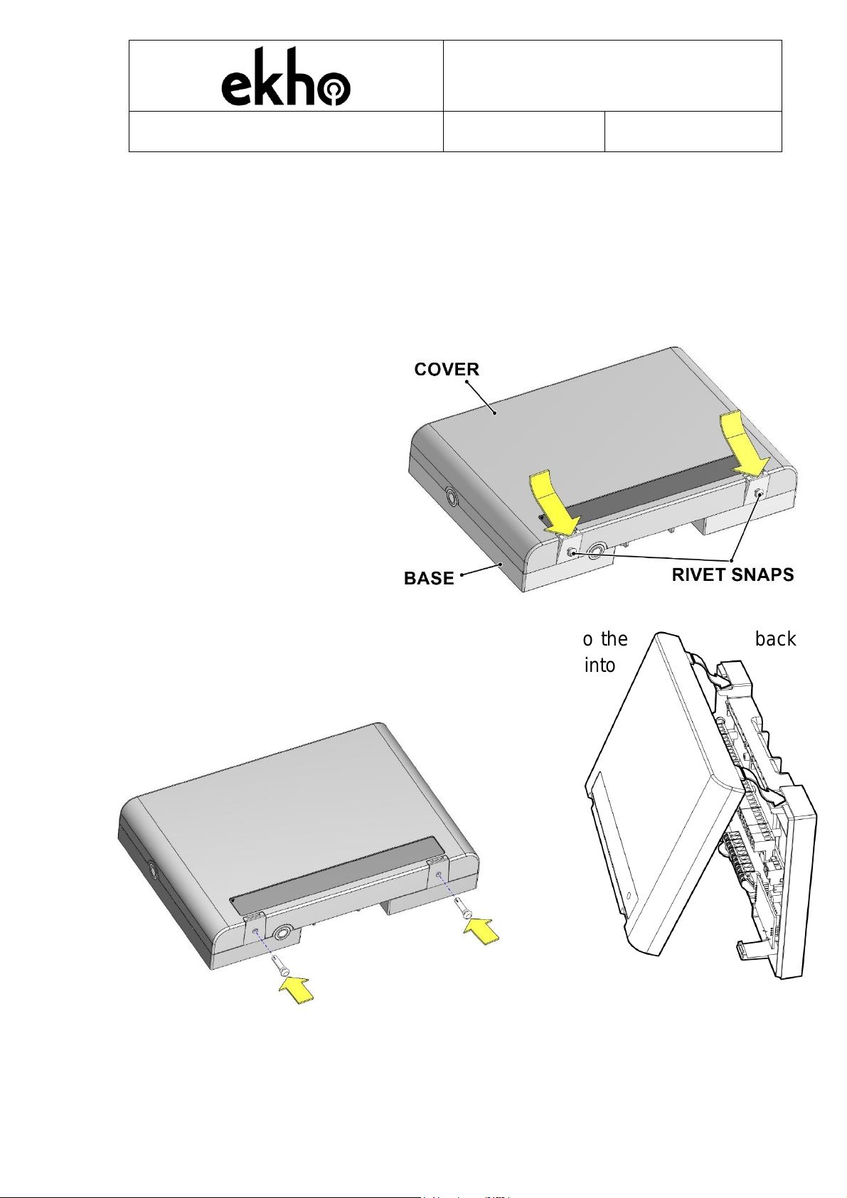
CONSTRUCTION
To open the cover, remove
the two rivet snaps by gently
pulling on the two cover clips.
In order to close the cover, first hook the cover onto the back
back plate, and apply pressure until the cover clicks into
place.
To secure the cover, you should insert the two rivet snaps into the holes.

EK-WL8-TRH/AU
WIRELESS TRANSLATOR
MODULE
STFV.425551.070-AU-UM rev. 8
20.07.2021
Page 6 of 23
Dimensions:
EK-WL8-TRH/AU
WIRELESS TRANSLATOR
MODULE
STFV.425551.070-AU-UM rev. 8
20.07.2021
Page 7 of 23
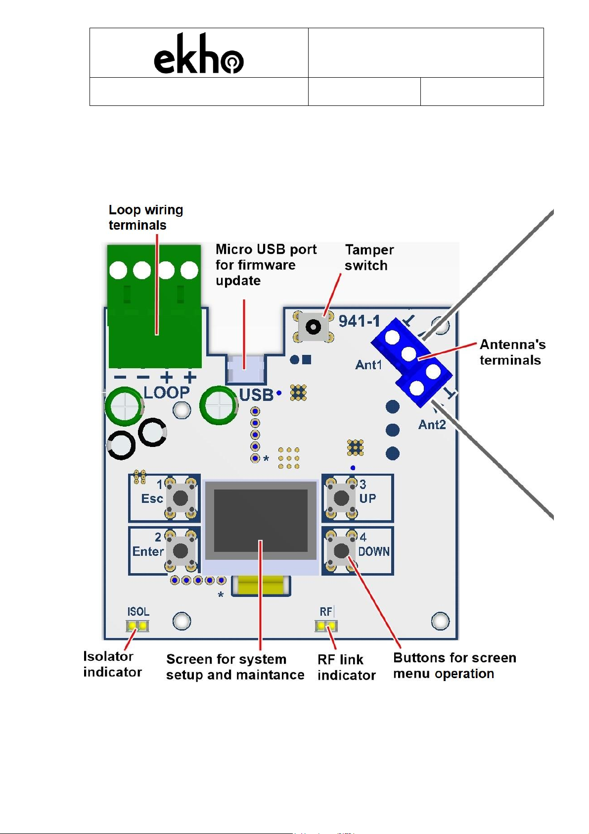
STRUCTURE
EK-WL8-TRH board
LOOP WIRING TERMINAL BLOCKS: Used for connecting the translator to
the analogue loop
DISPLAY: Used for configuring the wireless system

EK-WL8-TRH/AU
WIRELESS TRANSLATOR
MODULE
STFV.425551.070-AU-UM rev. 8
20.07.2021
Page 8 of 23
Micro USB PORT: Used for updating the firmware with a computer via a mi-
cro-USB cable and for connecting to the “Ekho Configuration” software.
ANTENNA TERMINAL BLOCKS: Can be used to replace the built-in anten-
nas with a third party external antenna. In order to do that, please remove the
existing antennas and insert coaxial cables from the external 868 MHz anten-
nas (connect the central conductor to socket "A").
NOTE: The use of External antenna’s is at the installers/users risk.
TAMPER: When the cover is opened, a "Fault" event is generated, this can
be disabled/enabled via the Ekho Configuration software or the translator
menu.
"ESCAPE/[1]" BUTTON: Used to exit from a menu or a sub-menu if the user
doesn’t want to apply the changes. A second function of this button is to be
used as a digit "1" for the pass code .
"ENTER/[2]" BUTTON: Used to select a menu or a sub-menu; confirming the
changes made to any parameters. A second function of this button is to be
used as a digit "2" for the pass code.
"UP/[3]"BUTTON: Used for navigating through menus or sub-menus; chang-
ing the parameters (as a value increase). A second function of this button is
to be used as a digit "3" for the pass code.
"DOWN/[4]" BUTTON: Used for navigating through menus or sub-menus;
changing the parameters (as a value decrease). A second function of this but-
ton is to be used as a digit "4" for the pass code.
ISOLATOR indicator: Green LED on: loop is normal and isolator is closed,
yellow LED on: short-circuit on the loop and the isolator is open.
RF indicator: Operates only if the translator is in expander mode. The green
LED indicates that the RF connection with the central node (other translators)
is present, the yellow LED indicates that RF connection with central node is
lost.

EK-WL8-TRH/AU
WIRELESS TRANSLATOR
MODULE
STFV.425551.070-AU-UM rev. 8
20.07.2021
Page 9 of 23
INSTALLATION
Avoid installing the translator close to:
-equipment that uses large amounts of electrical current
-large metal objects, structures or metal ceiling structures
-fluorescent lighting fixtures
-computers, and their peripheral and network cabling.
If there are other translators or wireless system expander modules, a distance
of at least 2 meters should be kept between them. In general, all wireless
devices (devices included) should be installed at least 2 meters apart from
each other.
It is recommended to install the translator and expanders at least 2 - 2.5 me-
ters from the floor.
Environmental conditions (temperature, humidity etc.) must be in the ranges
specified at the beginning of this manual.
After having installed the translator, make sure that the translator’s devices
(sensors, call points, etc.) are receiving a good, strong signal (refer to the
individual device manuals) at their installed location.
Install the translator module using screws, fixing point information is shown
below:
188*
155
180
120
127*
EK-WL8-TRH/AU
WIRELESS TRANSLATOR
MODULE
STFV.425551.070-AU-UM rev. 8
20.07.2021
Page 10 of 23
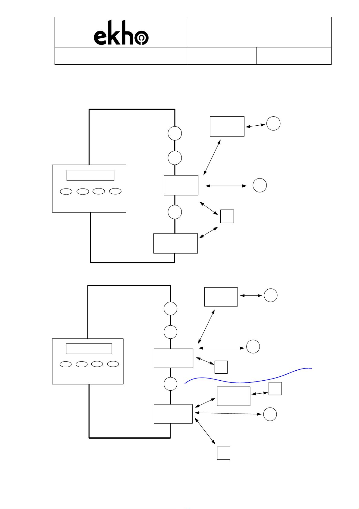
SYSTEM TOPOGRAPHY
There is one Ekho translator on a loop
Main control panel
Main TRH
Hochiki
Device#1
Hochiki
Device#2
Hochiki
Device#N
Expander
Ekho device #2
Ekho device #1
Ekho device #3
Ekho
subsystem
TRH as
Expander #N+1
There are two Ekho translators on a loop
Main control panel
Main TRH #1
Hochiki
Device#1
Hochiki
Device#2
Hochiki
Device#N
Expander
Ekho device #2
Ekho device #1
Ekho device #3
Subsystem
#1
Main TRH #2
Subsystem
#2
Expander
Ekho device #2
Ekho device #3
Ekho device #1

EK-WL8-TRH/AU
WIRELESS TRANSLATOR
MODULE
STFV.425551.070-AU-UM rev. 8
20.07.2021
Page 11 of 23
WIRING
TRANSLATOR WIRING
Before wiring the device, please consider the following:
-refer to and follow national codes of wiring and cabling practice and
other internationally recognized standards
-loop terminals are polarity sensitive
Connect the loop wiring to the translator’s terminal blocks as per the wiring
scheme in the following picture and table.
NOTE It's recommended not to install more than 10 translators on to a single
loop
Loop input Loop output
+
_+
_
Picture 6
Terminal
Function
Description
Comment
1
Loop –in
Loop negative in
2
Loop –out
Loop negative out
3
Loop + in
Loop positive in
Short circuit protected
4
Loop + out
Loop positive out
Short circuit protected
SHORT CIRCUIT ISOLATORS
The translator incorporates an integral short circuit isolator.

EK-WL8-TRH/AU
WIRELESS TRANSLATOR
MODULE
STFV.425551.070-AU-UM rev. 8
20.07.2021
Page 12 of 23
FINAL STEPS OF INSTALLATION
Configure the radio system either directly with the translator’s
keyboard/display or with a personal computer. System configuration and pro-
gramming will be described further in this manual.
PROGRAMMING
ACCESS PERMISSION
To access the "Configuration" menu a pass code needs to be entered (default
password- "33333"). It is possible to change the default pass code by entering
the "PSW Change" sub-menu which can be found in "Configuration"/"PSW
Change". To do this you should enter the Current pass code twice and then
the new pass code.
NOTE If the pass code is forgotten a factory reset (This action will erase any
program configuration) of the system will need to be performed. To do this
you should simultaneously press and hold button 1 and 3 and power cycle the
translator. The display will show "Clear all?". Select "Yes", the system will be
reset and the default pass code ("33333") can then be used.
EK-WL8-TRH/AU
WIRELESS TRANSLATOR
MODULE
STFV.425551.070-AU-UM rev. 8
20.07.2021
Page 13 of 23
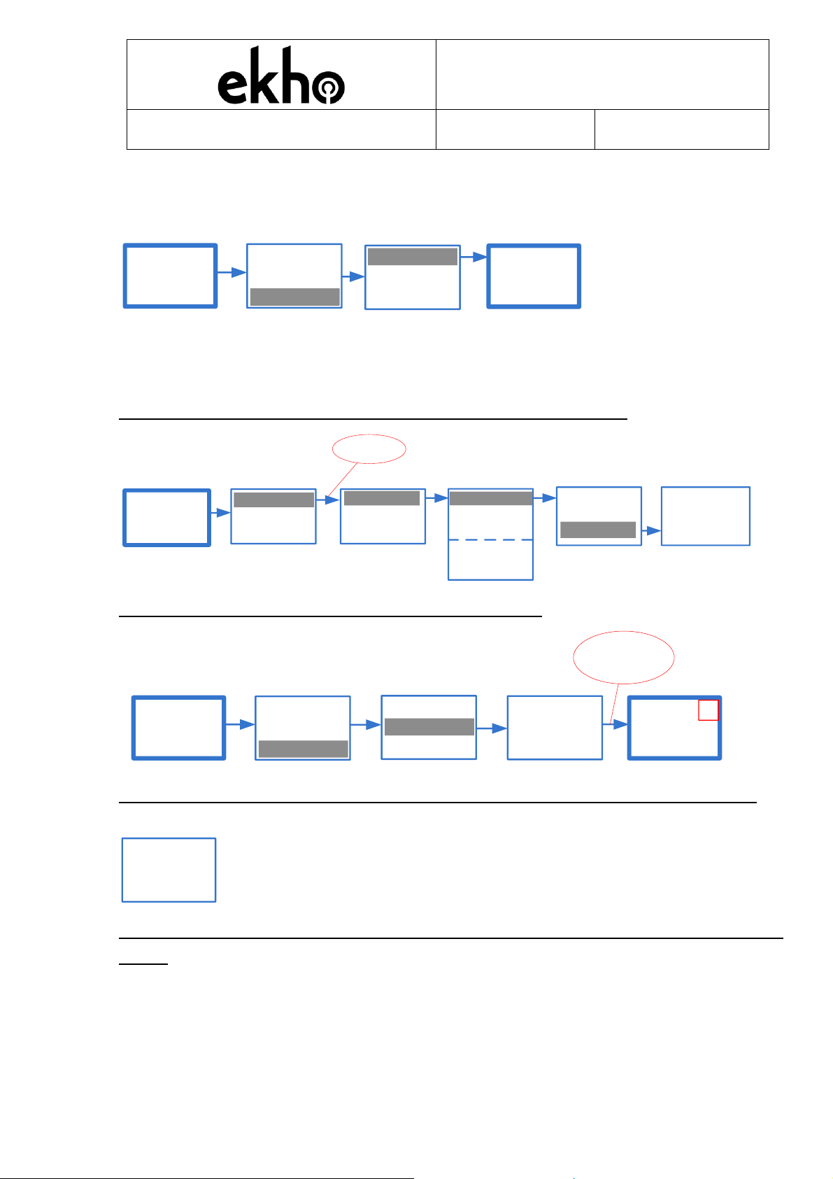
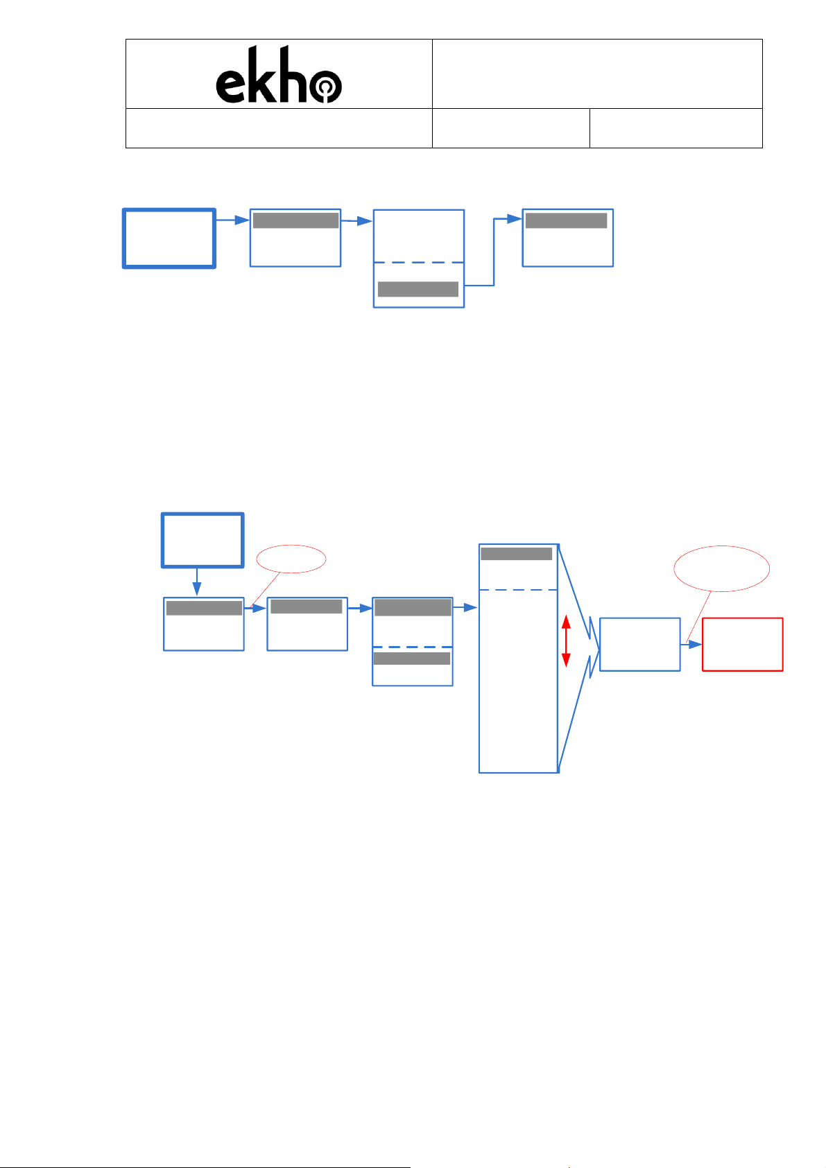
CREATING A NEW SYSTEM
Firstly, a central node(s) (Main TRH) should be created.
WL8-TRH
v x.x/RF v.y
A1 Yes
Create new
system?
Main TRH
TRH as Exp
WL8-TRH
v x.x/RF v.y
A1
The loop address will also need to be changed.
Once completed an additional TRH as expander can be added to the system.
STEP1 –add TRH as expander to main TRH configuration
Configuration
Maintenance
Password
Radio
Start Addr
Loop
001 wl8-trh(e)
etc.
--ADD NEW--
000 wl8-trh
002 wl8-os
WL8-EXPN
WL8-TRH
WL8-N Press prog.
button
...
MAIN TRH
WL8-TRH
v x.x/RF v.y
A1
STEP2- initialize TRH as expander in the system
WL8-TRH
v x.x/RF v.y
A1 Yes
Create new
system? TRH as Exp
Main TRH Initialization
is in progress
…
WL8-TRH(E)
v x.x/RF v.y
A1
TRH as expander
Waiting few
seconds
STEP3 –make sure the following message appears on Main TRH display
Device
added
successfully
MAIN TRH
STEP4 –change the loop address for TRH and TRH as expander via the
menu
EK-WL8-TRH/AU
WIRELESS TRANSLATOR
MODULE
STFV.425551.070-AU-UM rev. 8
20.07.2021
Page 14 of 23
CHOOSING THE RADIO PROTOCOL TYPE
Configuration
Maintenance Start Addr
Loop
PSW Change
WL8-TRH
v x.x/RF v.y
A7 Short!
Radio RSM-WTM
HWL8-TRH
Prot.type
The default protocol type is RSM-WTM. HWL8-TRH protocol type is reserved
for future use.
ADD/DEL DEVICES
The following steps describe the common procedures for adding or deleting
the devices from the wireless system.
1. The ADD command procedure is performed in the following way:
WL8-OH
WL8-O
WL8-H
WL8-OS
WL8-OV
WL8-HS
WL8-SND
WL8-CP
WL8-OUT
WL8-EXP
Press prog
button
…
Device
added
successfully
Configuration
Maintenance
Radio
Start Addr
Loop 000wl8-trh
Select
001wl8-trh(e)
002wl8-os
etc.
Password
WL8-TRH
v x.x/RF v.y
A1
--ADD NEW--
WL8-B
WL8-V
WL8-IN
WL8-N
WL8-EXPN
WL8-TRH
Press Prog.
button in devicce
After the ADD command is performed, the translator waits for a device to be
linked, to link a device press the device's "program button" (see the specific
installation manuals of these devices).
After a device has been linked the translator automatically assigns a subse-
quent address to this device. The whole sequence starts from the address
assigned to the translator ("Start Addr" menu option).
2.The following picture describes the DEL ("delete") command procedure,
which can be applied to devices that are already present in the wireless
configuration:
EK-WL8-TRH/AU
WIRELESS TRANSLATOR
MODULE
STFV.425551.070-AU-UM rev. 8
20.07.2021
Page 15 of 23
Configuration
Maintenance
Radio
Start Addr
Loop
--ADD NEW--
000 RR-V
Delete
Init
Info
Are you
sure?
Yes
Select
001 Aur-TS
002wl8-os
etc.
WL8-TRH
v x.x/RF v.y
A1 Password
Be aware that this command deletes a device from the configuration of the
translator, but not from the configuration of the main control panel.
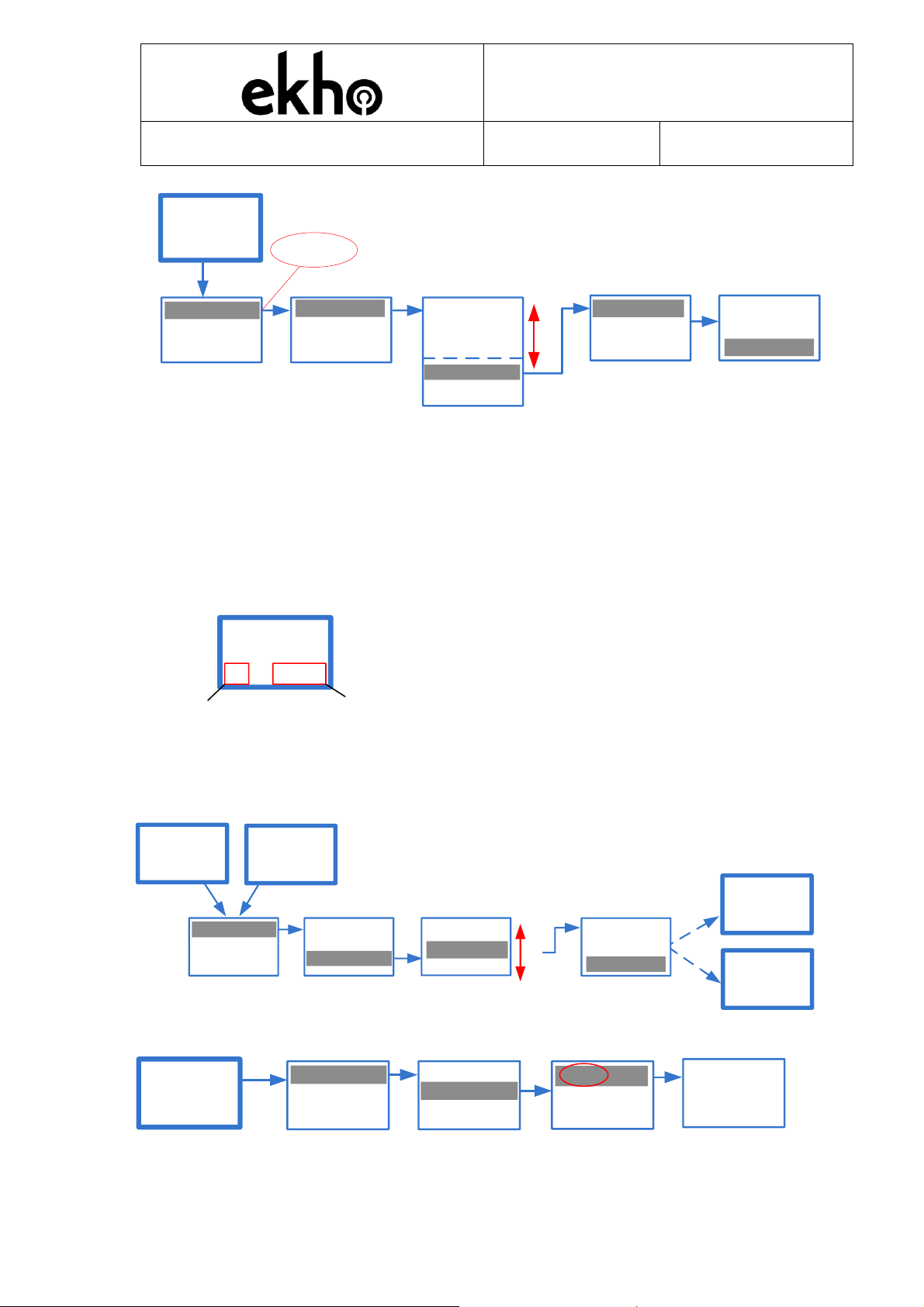
CHANGING THE START ADDRESS OF THE TRANSLATOR
WL8-TRH
v x.x/RF v.y
A1 Short!
Start
adress
Current
isolator state
Upper display menu
If the wired ESP loop has devices connected (for example, addresses 1 to
19 are occupied), you must change the start address (available from 1 to
127) to connect the following (wireless) devices:
Apply
new addr?
Yes
Configuration
Maintenance
Radio
Start Addr
Loop Start addr.
DOWN UP
20
WL8-TRH
v x.x/RF v.y
A1 WL8-TRH
v x.x/RF v.y
A20
Press
Esc
WL8-TRH(E)
v x.x/RF v.y
A2
WL8-TRH(E)
v x.x/RF v.y
A20
Confirmation that the correct address has been applied can be checked
wl8-trh
Radio addr.
000
Configuration
Maintenance
Radio
Loop
Start Adrr
020 POM
WL8-TRH
v x.x/RF v.y
A20

EK-WL8-TRH/AU
WIRELESS TRANSLATOR
MODULE
STFV.425551.070-AU-UM rev. 8
20.07.2021
Page 16 of 23
ADDRESSES CROSS-MAPPING
The Loop menu is used to display information regarding the entire address
table that the translator provides to the Hochiki ESP loop. It is also possible
to view the mapping between the Hochiki ESP loop devices and the radio
addresses.
wl8-trh
Radio addr.
000
Configuration
Maintenance
Radio
Loop
Start Adrr
007 POM
WL8-TRH
v x.x/RF v.y
A7 008 ALK-E
wl8-o
Radio addr.
001
wl8-ov
Radio addr.
002
009 ALK-E
136 BS
wl8-ov
Radio addr.
002
009+127=136
etc.
EKHO DEVICES AND ESP DEVICES TYPES
The actual ESP device(s) emulated by the translator on behalf of a EKHO
device will be as per the following table:
Wireless EKHO Device
ESP Device type
EK-WL8-TRH Hochiki Wireless Translator Module
CHQ-POM
EK-WL8-CP Wireless MCP
HCP-E
EK-WL8-O Wireless Optical Smoke Sensor
ALK-AS/ASN
EK-WL8-OH Wireless Multi-Sensor Sensor
ACB-ASN
EK-WL8-H Wireless Heat Sensor A1R
ACB-ASN
EK-WL8-OS Wireless Optical Smoke Sensor with
Built in Sounder
ALK-AS/ASN (Sensor)
CHQ-BS (Sounder)
EK-WL8-HS Wireless Heat A1R Sensor with Built in
Sounder
ACB-ASN (Sensor)
CHQ-BS (Sounder)
EK-WL8-IN Wireless Single Input Module
CHQ-S / CHQ-DIM
EK-WL8-OUT Wireless Single Output Module
CHQ-SIO/CHQ-MRC
EK-WL8-OV Wireless Optical Smoke Sensor with
Built in Voice Annunciator and VID
ALK-AS/ASN (Sensor)
CHQ-BS (Voice)
EK-WL8-SND Wireless Sounder
CHQ-BS
EK-WL8-EXP Wireless Expander Module
CHQ-POM

EK-WL8-TRH/AU
WIRELESS TRANSLATOR
MODULE
STFV.425551.070-AU-UM rev. 8
20.07.2021
Page 17 of 23
You can also view the address(es) occupied by every radio device:
Loop
address(es)
9,136
Configuration
Maintenance Loop
Radio
Start Adrr
WL8-TRH
v x.x/RF v.y
A7
000wl8-trh
001wl8-trh(e)
002wl8-ov
etc.
001wl8-o Edit
Delete
Info
Init
--ADD NEW--
Devices that combine fire sensors and sounders (for example, EK-WL8-OS,
EK-WL8-HS, EK-WL8-OV etc.) occupy two addresses on the ESP loop. The
sounder within these devices will be addressed automatically by adding 127
to the sensor address and then using this number as the sounder address
e.g. 9 (sensor address)+127=136 (sounder address).
When you add a new wireless device, it is added at the end of the list by
default.
When you delete a wireless device, the list shifts up automatically.
Example of wireless device deleting:
Radio
address
Radio Device
Loop address
before deleting
Loop address
after deleting
000
WL8-TRH
007
007
001
WL8-O
008
008
002
WL8-OV
009
-
136
-
003
WL8-IN
010
009
001
WL8-TRH(E)
Unknown
Unknown
etc.
etc.
etc.
NOTE WL8-TRH(E) radio address will be the same as some wireless device
addresses. This is normal as the radio address space for expanders differs
from other wireless devices address space.
PARAMETER EDITING
The basic parameters of the EKHO devices have the option to be changed
e.g. On/Off. Some parameters are not obvious, for example the EK-WL8-
TRH parameters. O
N / OFF

EK-WL8-TRH/AU
WIRELESS TRANSLATOR
MODULE
STFV.425551.070-AU-UM rev. 8
20.07.2021
Page 18 of 23
Configuration
Maintenance
Radio
Start Addr
Loop
Info
001wl8-o
Edit
Alarm sound
Alarm mess.
Message 2
Message 3
Message 1
Pulse 1s/1s
Pulse 2s/2s
Cont. tone
Dual 1s/1s
Dual .4s/.4s
Pulse .2s/1.3s
Tamper
Enabled
000wl8-trh
--ADD NEW--
WL8-TRH
v x.x/RF v.y
A1
)
Parameter
Value
Description
Alarm
sound
Cont. tone
Tone that is used
when the sounder is
operated from a fire
condition
Continuous one tone
Pulse 1s/1s
1s –ON /1s-OFF
Pulse 2s/2s
2s –ON /2s-OFF
Dual 1s/1s
1s –ON Tone1 /1s-ON Tone2
Dual .4s/.4s
0,4s –ON Tone1 /0,4s-ON
Tone2
Pulse
.2s/1.3s
0,2s –ON /1,3s-OFF
Alarm
mess.
Message 1
List of pre-recorded voice messages in the voice annun-
ciator (WL8-OV) that can be played in a fire condition
Message 2
Message 3
NOTE The tone frequency depends on the type of sounder being used and
is shown in the sounder and combined devices user manuals.
Operation mode of all sounders in a fire condition is selected in the settings
of the WL8-TRH (menu: Alarm sound)
Tones selectable via the DIP switches:-
Sound
alarm pa-
rameter
Switches condition on WL8-SND PCB (LEFT-RIGHT)
1(OFF) - 1(OFF)
1(OFF) - ON
ON –1 (OFF)
ON - ON
Cont. tone
Continuous tone
990Hz
Continuous
tone
990Hz
Unsynchronized
Dual tone
990Hz&650Hz
(250ms~250ms)
Unsynchronized
Pulsed tone
990Hz (500ms
On/500ms Off)
Pulse 1s/1s
Pulsed tone
(synchronized)
990Hz (1s
On/1s Off)
Pulse 2s/2s
Dual 1s/1s
Dual .4s/.4s
Pulse
.2s/1.3s

EK-WL8-TRH/AU
WIRELESS TRANSLATOR
MODULE
STFV.425551.070-AU-UM rev. 8
20.07.2021
Page 19 of 23
MAINTENANCE
Maintenance menu (not for WL8-TRH(E)) allows you to view the state of
wireless devices and send control commands:
Configuration ! 001wl8-o
! 003wl8-in
State
Control Tamper
Leds OFF
Green ON
Wink
Test
Generate
alarm ?
Yes
RFLink Qual
Maintenance
WL8-TRH
v x.x/RF v.y
A1
! 001wl8-trh(e) RF Link
Command
successfully
sended
S/N
43 dB
Excellent
"!" at the beginning of the line means that there is a problem with a wireless
device. By using the "State" menu, a user can obtain information about the
general state (alarm/no alarm) and all current fault conditions of the device.
Use the "UP" and "DOWN" buttons to scroll through the faults list.
NOTE After battery replacement in a child device wait at least 5 minutes for
any unexpected fault messages to disappear.
By using the "Control" menu you can turn the device’s LED on or off and ac-
tivate the "RF link Quality" mode. For sensors, it's also possible to generate
an alarm of the system.
In the "RF link Quality" mode, devices indicate their signal strength with the
wireless expander via a flashing LED:
-2 flashes RED –no connection
-1 flash RED –poor signal strength
-1 flash GREEN –good signal strength
-2 flashes GREEN –excellent signal strength
Devices automatically exit the "RF Link Quality" mode after 15 minutes.

EK-WL8-TRH/AU
WIRELESS TRANSLATOR
MODULE
STFV.425551.070-AU-UM rev. 8
20.07.2021
Page 20 of 23
In the "RF Link" mode the WL8-TRH displays the link quality with the selected
device refer to the table below:
Wireless signal quality (S/N)
Assessment
< 10 dB
Bad (no connection)
10 –24 dB
Weak
25 –35 dB
Good
> 35 dB
Excellent
NOTE After installation the signal strength should indicate 'good' or ‘excel-
lent’.
WARRANTY
All translators are covered by a 3year limited warranty. The warranty is voided
by mechanical or electrical damage caused by incorrect handling or usage.
Translator must be returned via an authorized supplier for repair or replace-
ment along with full information on the identified problem.
WARNINGS & LIMITATIONS
Devices use high quality electronic components and plastic materials that are
highly resistant to environmental deterioration. However, after 10 years con-
tinuous operation it is advisable to replace them to reduce the risk of reduced
performance caused by external factors. Ensure the devices are only used
with compatible control panels. Detection systems must be checked, serviced
and maintained on a regular basis to confirm correct operation.
Refer to and follow National Codes of Practice and other internationally rec-
ognized fire engineering standards. Appropriate Risk Assessment should be
carried out initially to determine correct design criteria and updated periodi-
cally.
Table of contents
Other EKHO Control Unit manuals


Popular Control Unit manuals by other brands


Dea
Dea 211E Operating instructions and warnings

Cisco
Cisco TelePresence MCU 4200 Series Getting started

Bristan
Bristan PM2 SHC3DIV C Installation instructions and user guide

Digiplex
Digiplex EVO DGP2-ANC1B instructions

Behringer
Behringer 130 DUAL VCA quick start guide

KLINGER SCHÖNEBERG
KLINGER SCHÖNEBERG INTEC K200-FS Assembly and Repair Instructions


