EKHO EK-WL8-EXP/AU User manual

EK-WL8-EXP/AU
WIRELESS EXPANDER MODULE
STFV.425551.030-AU-UM rev. 17
20.04.2020
Page 1 of 7
GENERAL DESCRIPTION
EK-WL8-EXP/AU is an expander mod-
ule which is used for repeating signals
and building a wireless network. The
expander receivessignals from nearby
detectors and sends them to the trans-
lator module, which then informs the
main control panel about the system
events. The signal can also travel
through a number of expanders. Ex-
panders can automatically organize in a wireless network and create backup com-
munication routes to the translator module.
The device is supplied with a mounting kit.
The product complies with the requirements of the AS ISO 7240.18 and AS ISO
7240.25 standards.
GENERAL OVERVIEW
EK-WL8-EXP

EK-WL8-EXP/AU
WIRELESS EXPANDER MODULE
STFV.425551.030-AU-UM rev. 17
20.04.2020
Page 2 of 7
FEATURES
•Bi-directional wireless communication
•Intelligent algorithms
•Tamper switch
•Automatic frequency and amplitude adjustment
TECHNICAL SPECIFICATION
Communication range to a child device
1200 m (open space)
Communication range to another expander
2000 m (open space)
Radio frequency
918-926 MHz
Modulation type
GFSK
Operating frequency channels
6
Radiated power
Not more than 25 mW
Receiver category (EN300-220-1)
1.5
Power supply
from 11Vdc to 28Vdc
AC or DC input voltage
like power supply
Max power consumption
80 mA
Max number of expanders in one system
127
Dimensions
210x145x40 mm
Weight
320 g
Max tolerated humidity
93% RH
Operating temperature range
from –10 °C to +55 °C
PROGRAMMING
The “Prog.” button on the expander module is used for initializing the expander in the
system. Please refer to the translator manual for full instructions on how to add an
expander to the system. The expander can also be initialized using the “Streletz-
Wizard” software.

EK-WL8-EXP/AU
WIRELESS EXPANDER MODULE
STFV.425551.030-AU-UM rev. 17
20.04.2020
Page 3 of 7
INSTALLATION
The device can be hanged on two
screws using the top holes and then
secured with more screws through the
bottom holes. It is recommended to
install the device at least 2 meters
from the ground.
Ideally, the device should be installed
at a certain distance from metallic ob-
jects, doors, and power lines, as they
can cause the communication dis-
tance to drop. It is also important to
avoid installing the device near elec-
tronics and computer equipment in order to protect it from potential electromagnetic
interference.
To secure the cover, you should
insert two rivet snaps into the
holes.
To remove the cover, delete the two
rivet snaps by pulling on the base
brackets.
EK-WL8-EXP/AU
WIRELESS EXPANDER MODULE
STFV.425551.030-AU-UM rev. 17
20.04.2020
Page 4 of 7
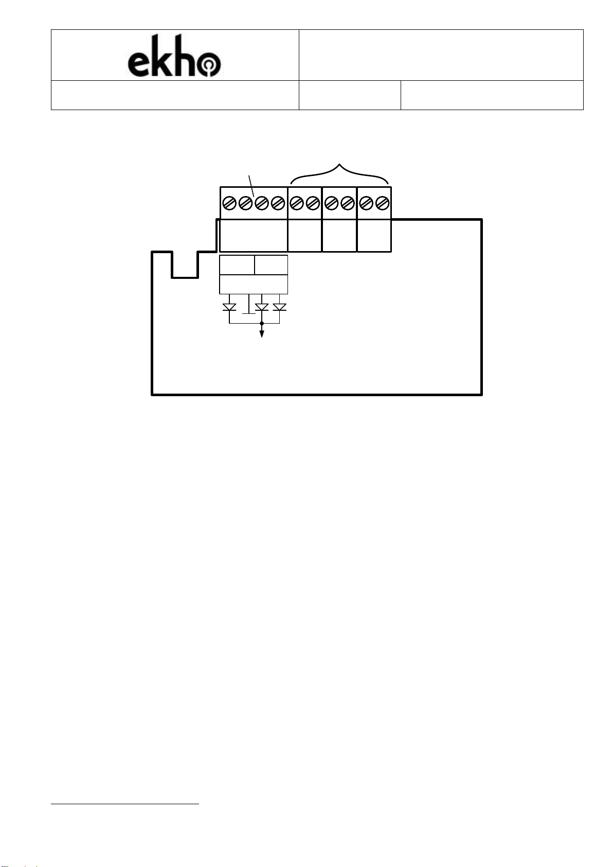
CONNECTORS
UNUSED
POWER
+-AC DC
Vcom
POWER
INPUT
NOTE Otherterminal blocks that arenot described (marked "UNUSED") do not affect
the operation of expander and are not used.
POWER
The device can be powered via an external power supply input.
Use any 12V or 24V power supply and connect it to the +/- inputs on the device.
ATTENTION Power supply should have an output current limit of 8 Amperes.
The AC and DC inputs are used for monitoring the state of the external power sup-
ply with backup (this options should be enabled in EK-WL8-TRH menu
1
). An exter-
nal power supply input in accordance with AS ISO 7240.4.
The expander measures the voltage levels between “–“ and each of these inputs. A
fault event will be generated if this value drops lower than 10.5 V. These inputs can
be directly connected to the open collector outputs on the power supply. In other
cases, you will need to provide power to these inputs through a normally closed fault
relay on the power supply. The AC and DC inputs monitoring can be switched off
translator menu.
1
Main and Backup power monitor modes should be set "ON"
EK-WL8-EXP/AU
WIRELESS EXPANDER MODULE
STFV.425551.030-AU-UM rev. 17
20.04.2020
Page 5 of 7
Expander power consumption:
Power supply
Voltage, Vdc
Current consumption, mA
External power
supply
12
65
24
35
INDICATION AND TESTING
The device has an LED which indicates its state according to the following:
LED
Color
State of the device
PW
Green
Normal state
Yellow
Main or backup power supply fault
Link
Green
Normal state
Yellow
No communication with the translator or other ex-
panders
If the device is powered on with opened case, it will activate the “connection quality
evaluation mode”. The connection strength is indicated with the “Link” LED for 15
minutes according to these rules:
Great (score 5)
-
two green blinks
Good (score 4)
-
one green blink
Bad (score 3)
-
one yellow blink
No connection (score 2)
-
two yellow blinks

EK-WL8-EXP/AU
WIRELESS EXPANDER MODULE
STFV.425551.030-AU-UM rev. 17
20.04.2020
Page 6 of 7
NOTE
You can check the RF quality in the place of installation in two ways: from the trans-
lator's menu or from Streletz-Wizard software.
By using "Maintenance/Device/Control" translator's menu it is possible to switch on
and off "RF link Quality" mode. Expander automatically exit this mode in 15 minutes.
ANALOG DATA
The expander provides the translator module with analog data about the air temper-
ature and RF link quality. This information can be viewed in the “Streletz-Wizard”
software.
Please refer to the software manual for full instructions on how to use the program
for system maintenance.
WARRANTY
All expanders are covered by a 5-year limited warranty. The warranty is voided by
mechanical or electrical damage caused by incorrect handling or usage. Expander
must be returned via an authorized supplier for repair or replacement along with full
information on the identified problem.
WARNINGS & LIMITATIONS
Devices use high quality electronic components and plastic materials that are highly
resistant to environmental deterioration. However, after 10 years continuous opera-
tion it is advisable to replace them to reduce the risk of reduced performance caused
by external factors. Ensure the devices are only used with compatible control panels.
Detection systems must be checked, serviced and maintained on a regular basis to
confirm correct operation.
Refer to and follow National Codes of Practice and other internationally recognized
fire engineering standards. Appropriate Risk Assessment should be carried out ini-
tially to determine correct design criteria and updated periodically.

EK-WL8-EXP/AU
WIRELESS EXPANDER MODULE
STFV.425551.030-AU-UM rev. 17
20.04.2020
Page 7 of 7
SAI Global ABN No
Lic SMK 41078 67 153 750 648
Hochiki Australia Pty Ltd
Block Y, Unit 1 Regents Park Estate
391 Park Rd, Regents Park
NSW 2143, Australia
Telephone: +61 2 9738 5566
Web: www.hochikiaustralia.com
Table of contents
Other EKHO Control Unit manuals


Popular Control Unit manuals by other brands


Acromag
Acromag BusWorks XT Series user manual

Geeetech
Geeetech 3D WiFi user manual

Wistron NeWeb
Wistron NeWeb XRAV-1 user manual

Beijer Electronics
Beijer Electronics GT-5422 user manual

SMC Networks
SMC Networks VOA325 Series Operation manual

Albalá Ingenieros, S.A.
Albalá Ingenieros, S.A. HLI3000C01 manual