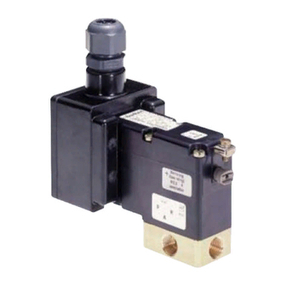
Burkert ACP016 Series User manual

Operating Instructions
Manuel d‘utilisation
Solenoid coil Type ACP016
Bobine magnétique Type ACP016
Device with Hazardous Locations Zone 1/21
and Class I, II, III Div 2 Listing
Appareil approuvé pour les emplacements
dangereux de zone 1/21 et de classe I, II, III, division 2

We reserve the right to make technical changes without notice.
Sous réserve de modifications techniques.
© Bürkert Werke GmbH & Co. KG, 2019-2020
Operating Instructions 2012/01_EU-ML_00815314 / Original EN

3
1 OPERATING INSTRUCTION ................................................. 4
1.1 Denitionsofterms ..................................................... 4
1.2 Symbols....................................................................... 4
2 INTENDED USE .................................................................... 5
2.1 Explosionprotectionapproval..................................... 5
2.2 Appliedstandards ....................................................... 6
3 BASIC SAFETY INSTRUCTIONS.......................................... 7
4 GENERAL INFORMATION .................................................... 8
4.1 Contactaddress.......................................................... 8
4.2 Warranty ...................................................................... 8
4.3 InformationontheInternet.......................................... 8
5 PRODUCT DESCRIPTION .................................................... 9
5.1 Structure...................................................................... 9
5.2 Solenoidcoilwithcableoutlet .................................. 10
5.3 Solenoidcoilwithterminalbox ................................. 10
6 SPECIFIC CONDITIONS OF USE ....................................... 10
6.1 Avoidingbuild-upofelectrostaticcharge.................. 10
6.2 Blockassembly ......................................................... 10
6.3 Operatingconditions ................................................. 11
6.4 Operatingtemperaturerange .................................... 11
6.5 Mechanicaldanger.................................................... 11
6.6 Supplyconnectionforsolenoidcoilwith
terminalbox............................................................... 11
7 TECHNICAL DATA............................................................... 12
7.1 Identicationofthesolenoidcoilwithcableoutlet ... 12
7.2 Identicationofthesolenoidcoilwithterminalbox .. 13
7.3 Typesofprotection.................................................... 14
7.4 Electricaldata............................................................ 15
8 ACCESSORIES ................................................................... 16
8.1 Cableglandforterminalbox ..................................... 16
8.2 Externalgroundingconnectionforterminalbox ....... 16
9 INSTALLATION AND REMOVAL ......................................... 16
9.1 Installation ................................................................. 17
9.2 Electricalconnection ................................................. 17
9.3 Removal .................................................................... 19
10 START-UP............................................................................ 19
11 MAINTENANCE, REPAIR, TROUBLESHOOTING .............. 20
11.1 Troubleshooting......................................................... 20
12 TRANSPORT, STORAGE, DISPOSAL................................. 20
Contents
english
ACP016

4
Operating Instruction
1 OPERATING INSTRUCTION
Theoperatinginstructionsdescribetheentirelifecycleofthe
device.Keeptheseinstructionsinalocationwhichiseasily
accessibletoeveryuserandmaketheseinstructionsavailableto
everynewownerofthedevice.
Operatinginstructioncontainimportantinformation.
▶Readtheoperatinginstructionscarefullyandfollowthe
safetyinstructionsinparticular.
▶Operatinginstructionsmustbeavailabletoeachuser.
▶Theliabilityandwarrantyforthedevicearevoidiftheoperating
instructionsarenotfollowed.
1.1 Denitions of terms
Theterm“device”usedintheseinstructionsappliestothe
solenoidcoilType ACP016.
1.2 Symbols
DANGER
Warns of an immediate danger.
▶Failuretoobservethewarningmayresultinafatalorseriousinjury.
WARNING
Warns of a potentially dangerous situation.
▶Failuretoobservethewarningmayresultinseriousinjuriesor
death.
CAUTION
Warns of a possible danger.
▶Failuretoobservethiswarningmayresultinamoderateor
minorinjury.
NOTE
Warns of damage to property.
Importanttipsandrecommendations.
Referstoinformationintheseoperatinginstructionsorin
otherdocumentation.
▶designatesaninstructiontopreventrisks.
→designatesaprocedurewhichyoumustcarryout.
english
ACP016

5
Intended use
2 INTENDED USE
Non-authorized use of the solenoid coil Type ACP016
may be a hazard to people, nearby equipment and the
environment.
The solenoid coil Type ACP016 is used to actuate valves
which control gaseous or liquid media.
▶Useaccordingtotheauthorizeddata,operatingconditions,
andconditionsofusespeciedinthecontractdocuments
andoperatinginstructions.
▶UsesolenoidcoilACP016onlyasspeciedontypelabel.
▶Usethesolenoidcoilonlyfortheapplicationcasesdesig-
natedinchapter„6Specicconditionsofuse“andincon-
junctionwiththird-partydevicesandthird-partycomponents
recommendedorapprovedbyBürkert.
▶ThetypeofprotectionisencapsulationEx“m”forcoilswith
cableconnection.
▶Thetypeofprotectionfortheoptionallymountedterminalbox
is“e”forgasand“t”fordust.
▶Correcttransportation,correctstorageaswellascorrect
assembly,installation,start-up,operationandmaintenance
areessentialforreliableandproblem-freeoperation.
▶Usethedeviceonlyforitsintendedpurpose.
2.1 Explosion protection approval
Theexplosionprotectionapprovalisonlyvalidifyouusethe
modulesandcomponentsauthorizedbyBürkert,asdescribedin
theseoperatinginstructions.
ThesolenoidcoilTypeACP016maybeusedonlyincombination
withthevalvetypesreleasedbyBürkert,otherwisetheexplosion
protectionapprovalwillbeterminated.Ifyoumakeunauthorized
changestothesystem,themodulesorcomponents,the
explosionprotectionapprovalwillalsobevoid.
ThefollowingULListingforSolenoidcoilACP016
wereissuedbythe: ULLLC
333PngstenRoad
Northbrook
IL60062-2096USA
english
ACP016

6
Intended use
2.2 Applied standards
USL - U.S. Listed investigation to UL 429
and
UL60079-0 EXPLOSIVEATMOSPHERES
-PART0:EQUIPMENT-
GENERALREQUIREMENTS
Edition6-
RevisionDate
2017/10/20
UL60079-7 STANDARDFOREXPLOSIVE
ATMOSPHERES-PART7:
EQUIPMENTPROTECTIONBY
INCREASEDSAFETY‘’E’’
Edition5-
RevisionDate
2017/04/21
UL60079-18 STANDARDFOREXPLOSIVE
ATMOSPHERES-PART18:
EQUIPMENTPROTECTIONBY
ENCAPSULATION‘M’
Edition4-
RevisionDate
2018/05/25
UL60079-31 EXPLOSIVEATMOSPHERES-
PART31:EQUIPMENTDUST
IGNITIONPROTECTIONBY
ENCLOSURE“T”
Edition2-
IssueDate
2015/06/12
Tab. 1: Applied standards USL
CNL - Canada Listed investigation to CSA C22.2 NO. 139
and
CSA C22.2
NO.60079-0
EXPLOSIVEATMOSPHERES
--PART0:EQUIPMENT--
GENERALREQUIREMENTS
Edition3-
IssueDate
2015/10/01
CSA
C22.2 NO.
60079-7:16
EXPLOSIVEATMOSPHERES
-PART7:EQUIPMENTPRO-
TECTIONBYINCREASED
SAFETY“E”
Edition2-
IssueDate
2016/10/01
CSA
C22.2 NO.
60079-18:16
EXPLOSIVEATMOSPHERES
-PART18:EQUIPMENT
PROTECTIONBYENCAPSU-
LATION“M”
Edition2-
IssueDate
2016/08/01
CSA
C22.2 NO.
60079-31:15
EXPLOSIVEATMOSPHERES-
PART31:EQUIPMENTDUST
IGNITIONPROTECTIONBY
ENCLOSURE‘T’
Edition2-
IssueDate
2015/10/01
Tab. 2: Applied standards CNL
english
ACP016

7
Basic safety instructions
3 BASIC SAFETY INSTRUCTIONS
Thesesafetyinstructionsdonotconsideranycontingenciesor
incidentswhichoccurduringinstallation,operationandmainte-
nance.
Theoperatorisresponsibleforobservingthelocation-specic
safetyregulations,alsowithreferencetothepersonnel.
Risk of injury from high pressure.
▶Beforeworkingonthesystemordevice,switchothepressure
andventordrainlines.
Risk of electric shock.
▶Beforereachingintothedevice,switchothepowersupply
andsecuretopreventreactivation.
▶Observeapplicableaccidentpreventionandsafetyregulations
forelectricalequipment.
Risk of burns and risk of re if used during long-term operation
through hot device surface.
Thesolenoidcoilcangetveryhotduringlong-termoperation.
▶Keepthedeviceawayfromhighlyammablesubstances
andmedia.
▶Donottouchthedevicewithbarehands.
Risk of explosion.
Thesolenoidcoilformaclosedsystemafterinstallation.When
usedinexplosion-riskareas,thereisariskofexplosionifthe
systemisopenedintheoperatingstate.
▶Donotremoveoropenthesystemduringoperation.
Risk of explosion due to electrostatic discharge.
Intheeventofasuddendischargefromelectrostaticallycharged
devicesorindividuals,thereisariskofanexplosioninthe
explosion-riskarea.
▶Takesuitablemeasurestoensurethatnoelectrostaticdis-
chargescanbuildupintheexplosion-riskarea.
▶Do not use the device in areas where there are powerful
chargegenerating processes, mechanical reaming and cut-
tingprocesses,thesprayingofelectrons(e.g.inthevicinity
ofelectrostaticcoatingequipment)aswellaspneumatically
conveyeddust.
▶Cleanthedevicesurfacebygentlywipingitwithadampor
antistaticclothonly.
To avoid the risk of explosion, the following must be observed
for operation in potentially explosive atmosphere:
▶Informationonthetemperatureclass,degreeofprotec-
tionandvoltageonthetypelabelforpotentiallyexplosive
atmosphere.
▶Repairsmayonlybeperformedbythemanufacturer.
▶Thedevicemustnotbeexposedtoanymechanicaland/or
thermalloadswhichexceedthelimitsspeciedintheoper-
atinginstructions.
▶Beforeopeningtheterminalbox,disconnectthepower
supply.
▶Theapplicablesafetyregulations(includingnationalregu-
lations)aswellasgeneraltechnicalstandardsmustbe
observedduringsetupandoperation.
english
ACP016

8
General information
General hazardous situations.
Topreventinjury,ensure:
▶Securesystem/equipmentagainstunintentionalactivation.
▶Observethedirectionofowduringinstallation.
▶Afteraninterruptioninthepowersupplyorpneumaticsupply,
ensurethattheprocessisrestartedinadenedorcontrolled
manner.
▶Donotmakeanyinternalorexternalchangesonthedevice
anddonotsubjectittomechanicalstress.
▶Installation,operationandmaintenancemayonlybeper-
formedbyqualiedspecialists.
▶Thedevicemustbeinstalledinaccordancewiththeregulations
applicableinthecountry.
▶Observethegeneralrulesoftechnology.
4 GENERAL INFORMATION
4.1 Contact address
Germany
BürkertFluidControlSystems
SalesCenter
Christian-Bürkert-Str.13-17
D-74653Ingelngen
Tel.+49(0)7940-10-91111
Fax+49(0)7940-10-91448
Email:[email protected]
International
Contactaddressescanbefoundonthenalpagesoftheprinted
operatinginstructions.
AndalsoontheInternetat:
www.burkert.com
4.2 Warranty
Thewarrantyisonlyvalidifthedeviceisusedasintendedinaccor-
dancewiththespeciedapplicationconditions.
4.3 Information on the Internet
OperatinginstructionsanddatasheetsforType ACP016canbe
foundontheInternetat:www.burkert.com
english
ACP016

9
Product description
5 PRODUCT DESCRIPTION
5.1 Structure
Components of the solenoid coil
ACP016 with cable outlet:
Connectionline
Components of the valve:
Fastening
screws
Coilhousing
Unionnut
Manual
control
Coverplate
Anchor
Diaphragm
Fluidhousing
Fig. 1: Valve with solenoid coil Type ACP016 with cable outlet
Components of the
solenoid coil ACP016 with
terminal box:
Terminal
box
Screwwith
springlock
washer
Ringcableshoe
withsupplyline
Washer
Components of the valve:
Fastening
screws
Manual
control
Coverplate
Anchor
Diaphragm
Fluidhousing
Coilhousing
Washer
Fig. 2: Valve with solenoid coil Type ACP016 with terminal box
english
ACP016

10
Specic conditions of use
5.2 Solenoid coil with cable outlet
ThesolenoidcoilACP016isanelectromagneticactuatorfor
variousBürkertvalves.Thevalvefunctionisbasedonthecon-
nectionofthesolenoidcoilwithauidhousing.Solenoidcoil
anduidhousingareconnectedwithfasteningscrews;thisis
whythesolenoidcoilACP016isincludedinthe
solenoidcoilswhicharescrewedtogetherasablock.
Thefasteningscrewsensureelectricalcontactbetweentheuid
housingandsolenoidcoil.
Thesolenoidcoilhousingiscomposedofepoxyresin.
Thepowersupplyisconnectedviaacable.Thecableisper-
manentlyintegratedinthesolenoidcoil,theunionnutisnot
intendedtoberemoved.Allmetalliccomponentsaregrounded
viatheprotectiveconductorinthecable.
Actuationispossiblewithalternatingvoltageordirectvoltage.
120Vand240Vonlyforalternatingvoltage(see„Tab.7“).Do
notpayattentiontopolarityonaccountoftheintegratedbridge
rectier.
Thesolenoidcoilalsoincludeselectronicpowerswitchingfor
reducingthepowerconsumptionduringoperation.
5.3 Solenoid coil with terminal box
Thestructureofthesolenoidcoilisidenticaltothedescription
under„5.2Solenoidcoilwithcableoutlet“,howeveraterminal
boxisalsoinstalledhere(see„Fig.2“).
Aconnectionkitforadditionalpotentialequalizationisenclosed
withtheterminalbox,observetheinformationinchapter„8.2“.
6 SPECIFIC CONDITIONS OF USE
6.1 Avoiding build-up of electrostatic
charge
DANGER
Risk of explosion due to electrostatic discharge.
Intheeventofasuddendischargefromelectrostaticallycharged
devicesorindividuals,thereisariskofanexplosioninthepoten-
tiallyexplosiveatmosphere.
▶Takesuitablemeasurestoensurethatnoelectrostaticdischarges
canbuildupinthepotentiallyexplosiveatmosphere.
▶Donotusethedeviceinareaswheretherearepowerfulcharge
generatingprocesses,mechanicalreamingandcuttingprocesses,
thesprayingofelectrons(e.g.inthevicinityofelectrostaticcoating
equipment)aswellaspneumaticallyconveyeddust.
▶Clean the device surface by gently wiping it with a damp or
antistaticclothonly.
▶Fluidhousingsmadeofbrassmustnotbeusedinatmo-
spherescontainingacetylene.
6.2 Block assembly
Thesolenoidcoilwithcableoutletcanbeablockassembly.The
griddimensionmustbeatleast37mm.Preferablyuseblocks
fromthemanufacturer.
Thesolenoidcoilwithterminalboxcannotbeablockassembly.
english
ACP016

11
Specic conditions of use
6.3 Operating conditions
WARNING
Warns of a potentially dangerous situation.
▶Failuretoobservethewarningmayresultinseriousinjuries
ordeath.
Theuidhousingperformsacoolingfunctionforthesolenoid
coil.
Operatethesolenoidcoilwithuidhousingonly.Theuid
housingmustcomplywiththefollowingrequirements:
Material Dimensions (L x W x H)
Brass,SS 32mmx46mmx18mm
PP,PVDF,PEEK 32mmx46mmx19mm
PVC 35mmx65mmx38mm
PTFE 35mmx76mmx38mm
Tab. 3: Fluid housing
Fluidhousingsmadeofthesamematerialwithlargerdimen-
sionsorwiththesamedimensionsmadeofamaterialwithbetter
thermalconductivitycanbeusedatanytime.
6.4 Operating temperature range
For each valve type observe the operating temperature range
speciedintheelectricaldata.
6.5 Mechanical danger
Thesolenoidcoilwithterminalboxshallbeoperatedonlyin
areaswhichhavealowriskofmechanicaldanger.Theyareeval-
uatedbytheoperator.Thesolenoidcoilwithcableoutletmay
alsobeusedinareaswithahighriskofmechanicaldanger.
6.6 Supply connection for solenoid coil
with terminal box
Forconnections,usewiressuitableforatleast90°C(194°F).
english
ACP016

12
Technical data
7 TECHNICAL DATA
DANGER
Risk of explosion.
If the safety data and values specied on the type label are
not observed or maintained, hazardous situations may be the
consequence.
▶Observethedegreeofprotectionandtemperatureclass
whenusingthedevice.
Itisasafetyrisktoexceedthevoltageindicatedonthetypelabel,
asthismaycausethedevicetooverheat.
▶Donotconnectthedevicetoavoltagewhichishigherthan
theonestatedonthetypelabel.
Itisasafetyrisktoexceedthemax.permittedswitchingfre-
quency,asthismaycausethedevicetooverheat.
▶Donotoperatethedeviceatahigherthanthemaximum
permittedswitchingfrequency.
7.1 Identication of the solenoid coil
with cable outlet
1
2
3
4
5
4
6
7
8
9
Solenoid coil ACP016 with cable outlet with uid
housing and position of the type label:
Fig. 3: Location and description of the Ex type label
english
ACP016

13
Technical data
Key:
Position Description
1ZoneidenticationUS
2ZoneidenticationCA
3Divisionidentication
4Typeidentication
5Nominalvoltage,frequencyandpower
6Ambienttemperature
7Serialnumber
8Manufacturinglocation,date
9IDnumber
Tab. 4: Identication of the solenoid coil with cable outlet
7.2 Identication of the solenoid coil
with terminal box
NOTE
Attachmentoftheterminalboxchangesthetypeofprotection.
1
2
3
4
5
4
6
7
8
9
Solenoid coil ACP016 with
terminal box with uid
housing and the positions
of the type labels:
Fig. 4: Location and description of the Ex type labels
english
ACP016

14
Technical data
Key:
Position Description
1ZoneidenticationUS
2ZoneidenticationCA
3Divisionidentication
4Typeidentication
5Nominalvoltage,frequencyandpower
6Ambienttemperature
7Serialnumber
8Manufacturinglocation,date
9IDnumber
Tab. 5: Identication of the solenoid coil with terminal box
7.3 Types of protection
TheExidenticationcomplieswiththetypesofprotectionofthe
particularcomponentsused.
Model Internal
code
Ex marking
Cable
outlet
CB+
JWxx1)
CII,Zn1,AExmbIICT4Gb
Zn21,AExmbIIICT130°CDb
USzone
marking
ExmbIICT4GbX
ExmbIIICT130°CDbX
CAzone
marking
CII,Div2,GrA,B,C,DT4
CIII,III,Div2,GrF,GT4
US & CA
division
marking
Terminal
box Jx2)
CII,Zn1,AExebmbIICT4Gb
Zn21,AExmbtbIIICT130°CDb
USzone
marking
ExebmbIICT4GbX
ExmbtbIIICT130°CDbX
CAzone
marking
CII,Div2,GrA,B,C,DT4
CIII,III,Div2,GrF,GT4
US & CA
division
marking
Tab. 6: Ex identication
1) Dierent cable lengths
2) Terminal box, comp. „Tab. 9“
english
ACP016

15
Technical data
7.4 Electrical data
Nominalvoltage/Frequency 24V/DC,60Hz
120V/60Hz
240V/60Hz
Voltagetolerance ±10%
Nominalpower 40W
Reducednominalpower 3W
Ratedcurrent 0.18...1.6A
Reducedratedcurrent 0.014...0.11A
Ambienttemperaturerange –40...+60°C(–40...+140°F)
Operatingmode Long-termoperation
Intermittentoperation
Tab. 7: Electrical data
Observethemaximumpermittedambienttemperature
rangeindicatedforeachvalvetypeunderoperatingcon-
ditionsofthevalve.
Maximumswitchingfrequency 301/min
Minimumcurrentlessinterval 0.5s
Tab. 8: Permitted parameters for intermittent operation
DANGER
Risk of explosion due to overheating.
▶Donotconnectthedevicetoavoltagewhichishigherthan
theonestatedonthetypelabel.
▶Donotoperatethedeviceatahigherthanthemaximum
permittedswitchingfrequency.
7.4.1 Electrical connection
Material3): Polyolen
Temperatureoperatingrange3): –55...+145°C(–67...+293°F)
forxedinstallation
Minimumbendingradius3): 4xexternaldiameterforxed
installation
Externaldiameter3): 6.2mm
Structureandfunction: 3xstrandedcopperwire
0.5mm2/LNPE
Halogen-freeaccordingto: IEC60754-1
Variants Code Enclosure type
Permanently
installedcable CB+
JWxx4)
Thisequipmentmustbemounted
inanUL/cULAExeb/Exebresp.
AExtb/Extbenclosurecertiedfor
useinClassI,Zone1resp.Zone
21.
Terminalbox
withinternal
threadM20x1.5
JF Type 1
Terminalbox
withinternal
threadNPT1/2
JG Type 1
Tab. 9: Electrical connection
3) Information according to the manufacturer
4) Dierent cable lengths
english
ACP016

16
Accessories
8 ACCESSORIES
8.1 Cable gland for terminal box
Devicemust be installed inaccordancewith Article 505
and506oftheNational ElectricalCode(ANSI/NFPA 70)
forinstallationintheUnitedStates,orSection18ofthe
CanadianElectricalCodeforinstallationsinCanada.Note
thattheoperatingtemperatureofthecableglandmustbe
atleast15Kabovethemaximumambienttemperature.
8.2 External grounding connection for
terminal box
Ifsolenoidcoilsfeatureaterminalbox,connectionterminalsare
enclosedfortheexternalgroundingconnection.
Ifthepotentialequalizationisnottobeconnectedbyapipeline
orbytheuseofaplastictting,theconnectioncanbemadevia
theexternalgroundingconnection.Itsuseisthereforeoptional
andmustbeassessedbytheoperator.
Theconnectioncapacityoftheringcablelugis4...6mm2and
thetighteningtorqueis1.2Nm.Theconnectionismadeas
shownin„Fig.6“.
9 INSTALLATION AND REMOVAL
DANGER
Risk of injury from high pressure.
▶Beforeworkingonthesystemordevice,switchothepressure
andventordrainlines.
Risk of electric shock.
▶Beforereachingintothedevice,switchothepowersupply
andsecuretopreventreactivation.
▶Observeapplicableaccidentpreventionandsafetyregulations
forelectricalequipment.
Risk of burns and risk of re if used during long-term operation
through hot device surface.
▶Keepthedeviceawayfromhighlyammablesubstances
andmedia.
▶Donottouchthedevicewithbarehands.
Risk of short circuit due to damaged connection cable.
▶The coil connection cable have to be xed and protected
againstdamage.
Risk of explosion.
Thesolenoidcoilformaclosedsystemafterinstallation.When
usedinpotentiallyexplosiveatmosphere,thereisariskof
explosionifthesystemisopenedintheoperatingstate.
▶Thesystemmustnotbedisassembledduringoperation.
english
ACP016

17
Installation and removal
DANGER
Risk of explosion due to electrostatic discharge.
Intheeventofasuddendischargefromelectrostaticallycharged
devicesorindividuals,thereisariskofanexplosioninthepoten-
tiallyexplosiveatmosphere.
▶Takesuitablemeasurestoensurethatnoelectrostaticdischarges
canbuildupinthepotentiallyexplosiveatmosphere.
▶Donotusethedeviceinareaswheretherearepowerfulcharge
generatingprocesses,mechanicalreamingandcuttingprocesses,
thesprayingofelectrons(e.g.inthevicinityofelectrostaticcoating
equipment)aswellaspneumaticallyconveyeddust.
▶Clean the device surface by gently wiping it with a damp or
antistaticclothonly.
WARNING
Risk of injury from improper installation.
▶Installationmaybecarriedoutbyauthorizedtechniciansonly
andwiththeappropriatetools.
▶Securesystemfromunintentionalactivation.
▶Followingassembly,ensureacontrolledrestart.
9.1 Installation
DevicemustbeinstalledinaccordancewithArticle505
and506oftheNationalElectricalCode(ANSI/NFPA70)
forinstallationintheUnitedStates,orSection18ofthe
CanadianElectricalCodeforinstallationsinCanada.
Detailedinstallationinstructionscanbefoundinthe
operatinginstructionsoftherespectivevalveand/or
onlineat:www.burkert.com
9.2 Electrical connection
DANGER
Risk of electric shock.
▶Beforereachingintothedevice,switchothepowersupply
andsecuretopreventreactivation.
▶Observeapplicableaccidentpreventionandsafetyregulations
forelectricalequipment.
Thereisariskofelectricshockifthereisnoelectricalcontact
betweenthemetalpartsofthevalveandtheprotectivecon-
ductorofthecoil.
▶Alwaysconnecttheprotectiveconductor.
▶Testforcontinuitybetweentheprotectiveconductorofthe
coilandthecoreguidetubeofthevalve.
english
ACP016

18
Installation and removal
If solenoid coils feature a terminal box, also observe the
following:
▶Insertpermanentlyinstalledcablesandlinesonly.
▶Useasuitablecableandlineentry(seechapter„8“).Observe
specicationsintheenclosedoperatinginstructions.
▶Intheterminalboxconnectonlywireswhichhavearatedcon-
nectionbetween0.5mm2and2.5mm2.
▶Tightenterminalscrewsto0.25Nm.
▶Lockhousingcoverproperly.Tightenlockscrewto2Nm.
▶Checkcontinuityoftheprotectiveconductorconnection.
▶Beforeopeningthehousingcover,disconnectthepowersupply.
▶Connectmaximumtwoconductorstoeachterminal.
External grounding connection for terminal box:
▶Theconnectionterminalsfortheexternalearthconnection,
whicharepackedfordeliveryinabagandbondedtothehous-
ingcover,mustberemovedduringinstallationofthedevice.
9.2.1 Solenoid coils with cable outlet
Theconnectioncableisencapsulatedwiththesolenoid
coilTypeACP016andcannotberemoved.
Observetheindicatedvoltageaccordingtothetype
label.
Wire color Assignment
green/yellow Protectiveconductor
black Phase/positivepole(+)
black Neutralconductor/
negativepole(-)
Tab. 10: Wire assignment
9.2.2 Solenoid coils with terminal box
green-yellow
black
black
Position Terminal
assignment
Protective
conductor
Neutralconductor/
negativepole(-)
Phase/
positivepole(+)
Fig. 5: Terminal box
Screw
springlockwasher
Washer
Washer
Ringcablelugwithsupplyline
Fig. 6: Connection of external potential equalization
english
ACP016

19
Start-up
9.3 Removal
DANGER
Risk of injury from high pressure.
▶Before loosening the lines and valves, turn o the pressure
andventthelines.
Risk of electric shock.
▶Beforereachingintothedevice,switchothepowersupply
andsecuretopreventreactivation.
▶Observeapplicableaccidentpreventionandsafetyregulations
forelectricalequipment.
WARNING
Risk of injury from improper removal.
▶Removalmaybecarriedoutbyauthorizedtechniciansonly
andwiththeappropriatetools.
Risk of injury due to media escaping from leaky connections.
▶Sealtheconnectionlinescarefully.
→Separatetheelectricalconnections.
→Separatethevalvebodyfromthepipeline.
NOTE
Malfunctions due to dirt.
▶RemovetheoldPTFEtapefromtheconnectionsduringre-
installs.Taperesiduemustnotgetintothepipeline.
10 START-UP
WARNING
Risk of injury from improper operation.
Improperoperationmayresultininjuriesaswellasdamageto
thedeviceandtheareaaroundit.
▶Beforestart-up,ensurethattheoperatingpersonnelarefamiliar
withandcompletelyunderstandthecontentsoftheoperating
instructions.
▶Observethesafetyinstructionsandintendeduse.
▶Onlyadequatelytrainedpersonnelmaystartuptheequip-
mentorthedevice.
Before start-up, ensure that
→thedevicehasbeeninstalledaccordingtotheinstructions,
→theconnectionhasbeenmadeproperly,
→thedeviceisnotdamaged,
→allscrewshavebeentightened.
english
ACP016

20
Maintenance, Repair, Troubleshooting
11 MAINTENANCE, REPAIR,
TROUBLESHOOTING
DANGER
Danger due to improper maintenance and repair work.
Impropermaintenanceandrepairworkmayresultininjuriesas
wellasdamagetothedeviceanditsenvironment.
▶Onlytrainedtechniciansmayperformmaintenancework.
▶Performmaintenanceworkwithsuitabletoolsonly.
▶Haverepairworkonthedeviceperformedbythemanufac-
tureronly.
▶Whenmaintainingorrepairingthesystem,donotopen
thevalveanddonotdisconnecttheprotectiveconductor
connection.
11.1 Troubleshooting
Intheeventofmalfunctions,makesurethat
→thedevicehasbeeninstalledaccordingtotheinstructions,
→theconnectionhasbeenmadeproperly,
→thedeviceisnotdamaged,
→thevoltageandpressurehavebeenswitchedon,
→thepipelinesarefree,
→allscrewshavebeentightened.
12 TRANSPORT, STORAGE,
DISPOSAL
NOTE
Transport damage.
Inadequatelyprotecteddevicesmaybedamagedduring
transportation.
▶Protectthedeviceagainstmoistureanddirtinshock-resis-
tantpackagingduringtransportation.
▶Preventthetemperaturefromexceedingordroppingbelow
thepermittedstoragetemperature.
Incorrect storage may damage the device.
▶Storethedeviceinadryanddust-freelocation.
▶Storagetemperature–40...+80°C(–40...+176°F).
Damage to the environment caused by device components
contaminated with media.
▶Disposeofthedeviceandpackaginginanenvironmentally
friendlymanner.
▶Observeapplicabledisposalandenvironmentalregulations.
english
ACP016
Table of contents
Other Burkert Control Unit manuals

Burkert
Burkert 3320 User manual

Burkert
Burkert 0127 User manual

Burkert
Burkert 2060 User manual

Burkert
Burkert 623969 User manual

Burkert
Burkert 6518 User manual

Burkert
Burkert 2301 Series User manual

Burkert
Burkert 2657 User manual

Burkert
Burkert 0420 User manual

Burkert
Burkert 2100 series Guide

Burkert
Burkert 2064 User manual

Burkert
Burkert 0287 User manual

Burkert
Burkert ME44 User manual

Burkert
Burkert Type 2000 User manual

Burkert
Burkert 0211 User manual

Burkert
Burkert 6510 User manual

Burkert
Burkert 2103 Series User manual

Burkert
Burkert 6027 User manual

Burkert
Burkert 2301 Series User manual

Burkert
Burkert 2060 Guide
Burkert
Burkert Type 2000 User manual