manuals.online logo
Brands
  1. Home
  2. •
  3. Brands
  4. •
  5. Savant
  6. •
  7. Control Unit
  8. •
  9. Savant SKL-3040-00 User manual

Savant SKL-3040-00 User manual

SKL-3040-00 Quick Reference Guide | 009-1796-02 1 of 3 45 Perseverance Way, Hyannis MA 02601
Copyright © 2022 Savant Systems Inc | 220221 Savant.com | 508.683.2500
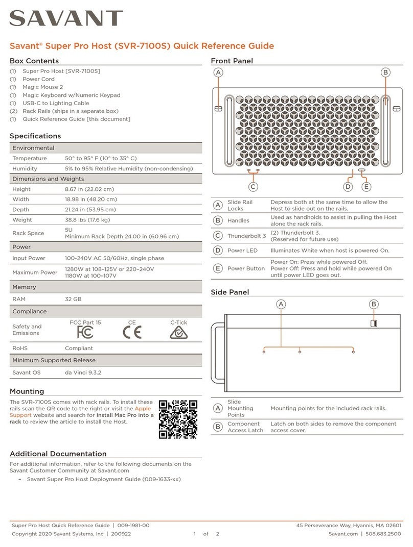
Savant® 40 Keypad Power and Control Module [SKL-3040-00]
Quick Reference Guide
Front View
Main Power
Keypad Bus 1
Keypad Bus 2
Keypad Bus 3
Ethernet
Keypad Bus 4
Keypad Bus 5
Reset
Status
A
B
C
D
E
F
Box Contents
Additional Items
Specifications
(1) 40 Keypad Power and Control Module (SKL-3040-xx)
(5) 4-pin Screw Down Plug-in Connectors (028-0834-xx)
(1) Power Supply to 120V AC Cable (064-0420-xx)
(1) ½inch nylon bushing for ½inch knockouts (015-0216-xx)
(1) Product Regulatory Statement (009-1950-xx)
–PWM-PENC3 Power Module Enclosure
–Echo, Metropolitan, or Ascend Low-Voltage Keypads.
–SHA-PENC3 Power Module Enclosure (older model enclosure)
–SHA-W1000 Low Voltage Keypad Wire
Dimensions and Weights
Height Width Depth Weight
SKL-3040 14.87 inch
(37.78 cm)
3.43 inch
(8.71 cm)
2.25 inch
(5.72 cm)
2.30 lbs
(1.04 kg)
Shipping 16.0 inch
(40.64 cm)
4.0 inch
(10.16 cm)
4.0 inch
(10.16 cm)
3.30 lbs
(1.50 kg)
NOTE: The height dimension includes the captive screw, and the
depth dimension includes the connectors.
Recommended Max Wiring Distance (per keypad bus)
New installations should use #14 AWG only. Retrofits with existing
wiring can be used as long as wire gauge and lengths are within
the following guidelines:
#14 AWG 1000 feet (304.80 meters)
#16 AWG 700 feet (213.36 meters)
#18 AWG 500 feet (152.40 meters)
–Cable length limits are due to voltage drops across the line.
–The SHA-W1000 cable available from Savant is manufactured
with very stringent standards and reduces the likelihood of
receiving interference from an outside source.
Power
Input 120 - 240V AC, 50/60 Hz, 480 watts
Output 24V DC
Regulatory
RoHS Compliant
Minimum Supported Release
Savant OS da Vinci 9.0
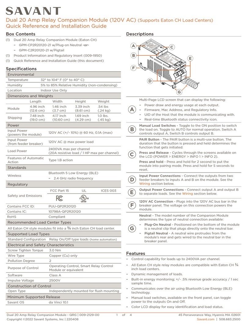
AKeypad Bus (1-5) - Up to 10 low voltage keypads wired in
a daisy-chain fashion are supported per keypad bus with a
maximum of 40 keypads per power module.
B
Status LED - Keypad Bus 1-5 - Each LED indicates the state
of that keypad bus. More information below.
Boot Process - The various states that can occur just after
power is applied and the SKL-3040 begins the boot-up
process are described below.
1.5s 7s
.5s .5s
Keypad
Discovered
Keypad Not
Discovered
REPEAT
1. Apply power to the SKL-3040
2. Status LED lights solid green for 1.5 seconds and then
changes to orange.
3. LED stays lit orange for 7 seconds during the boot-
loader process.
4. After the boot-loader completes, the LED repeatedly
blinks green then orange, indicating the beginning of the
keypad discovery process.
5. Starting with Keypad Bus 1, when at least one keypad on
that bus is discovered, the LED switches to solid green. If
no keypads are found, the LED switches to solid orange.
6. The discovery process continues until all the keypad
buses (1-5) are inspected.
Environmental
Temperature 32° to 104° F (0° to 40° C)
Humidity 10% to 80% Relative Humidity (non-condensing)
SKL-3040-00 Quick Reference Guide | 009-1796-02 2 of 3 45 Perseverance Way, Hyannis MA 02601
Copyright © 2022 Savant Systems Inc | 220221 Savant.com | 508.683.2500
C
Reset Button - Press and release the reset button begins
the keypad discovery process.
HELPFUL! Each time a new keypad gets added to the
bus, press the reset button to start the discovery
process.
D
Status LED - Keypad Lighting Module - Indicates the state
of the SKL-3040. The various states are shown below.
Normal operation. The SKL-3040
is connected to a network and
communicating with a Savant Host.
.5s 2s
REPEAT
Module is not connected to a
network. Verify the Ethernet cable
is plugged in and connected to a
network switch.
.5s2s
REPEAT
A firmware update is in process.
.5s .5s 2s
REPEAT
The module is connected to a
network (has IP Address), but
can't communicate with the Savant
Host. Verify the Host is powered
on and plugged into the local
network.
.5s.5s .5s 2s
REPEAT
The module is connected to a
network, can communicate with
the Savant Host, but the SKL-
3040 device is not listed in the
configuration running on the Host.
EEthernet - Connect to a network switch via Cat 5/5e/6
cable.
F
Main Power LED - Indicates whether power is applied to the
module.
– Green = Power Applied
– O = No Power.
B
cont.
As described above, during the boot-up
process, a solid orange LED indicates either:
–No keypad was detected during the
discovery process.
-- OR --
–Power was recently applied, and the SKL-
3040 is in the boot-loader state. The LED
is lit solid orange for about seven seconds
while in this state.
If the LED changes to solid green, this indicates
at least one keypad on the keypad bus was
detected.
1. Remove power at the circuit breaker.
2. Remove the lid from enclosure (if lid is installed).
3. Turn the captive screw on the AC compartment panel
counterclockwise (CCW) until the screw pops up.
4. Slide the cover up and away from the AC compartment. Set
cover aside.
5. Remove the two WAGO 6-position push connectors that were
shipped in the AC compartment and set aside.
6. Remove one of the electrical knockouts at the bottom of the
enclosure and install a ½inch electrical cable clamp.
7. Remove the electrical knockout from module slot 1 and snap
the supplied ½inch nylon insulating bushing in its place.
When installing more than one module, repeat step 7 on the
remaining module slots.
Lighting Module Enclosure (PWM-PENC3)
Prep the Enclosure (PWM-PENC3)
With the enclosure mounted, the next step is to prep it to accept
the lighting keypad modules. Follow the steps below to prep the
enclosure.
The PWM-PENC3 is a metal enclosure that can house up to three
SKL-3040 low voltage lighting power modules. This enclosure
ensures the modules are installed in a safe, well-protected
ventilated case. Mount the enclosure to a wall or similar before
continuing to the next section. Mounting instructions are available
in the Low Voltage Power Module Enclosure Quick Reference
Guide available on the Savant Customer Community.
Module
Slot 1
Slide up and
then out
Module
Slot 2
Module
Slot 3
4
3
6
7
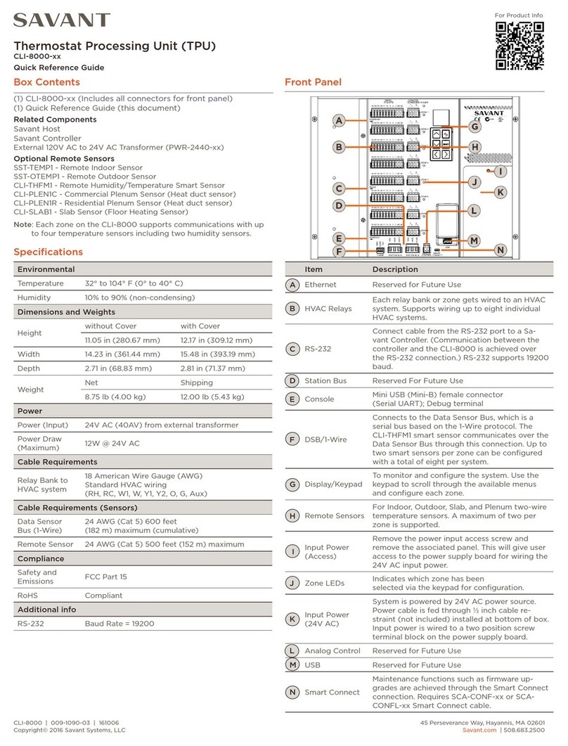
Prep the Lighting Keypad Module Power Supply
Before mounting the module into the enclosure, the 120/240V AC
wires that supply power to the modules must be installed. See
instructions below.
1. Remove the keypad power module and corresponding
120/240V AC cables from shipping box.
2. Flip module over to access the power supply.
3. Plug the supplied 120/240V AC cable into the 2-pin connector
located on the power supply board's bottom edge. The
connector is keyed to avoid plugging the connector in
backwards. See diagram below:
Keypad Module Power Supply
Neutral (White)
Hot (Black)
Green (Gnd)
SKL-3040-00 Quick Reference Guide | 009-1796-02 3 of 3 45 Perseverance Way, Hyannis MA 02601
Copyright © 2022 Savant Systems Inc | 220221 Savant.com | 508.683.2500
Once all keypad modules are mounted, they can then be wired to
the incoming AC circuit.
Before making any electrical connections, install the keypad power
modules into the PWM-PENC3 enclosure. Refer to the diagram at
the bottom of this page for reference
The lighting keypad module communicates with the Savant Host
over a standard Cat 5/5e/6 cable. Both T1/E1 568A are supported.
Connect an Ethernet cable between the module's Ethernet
connection and a local network switch. See the image below:
The cable in the image below shows the supplied five-inch (5)
conductor keypad pigtail cable spliced to the SHA-W1000 cable.
The SHA-W1000 cable runs through the walls of a home and joins
the SKL-3040's keypad bus connection with each keypad. Savant
recommends the SHA-W1000 cable assembly for these cable runs.
Use the diagram below for reference when making the splices.
6. Verify the 120/240V AC feed from the circuit breaker is O.
7. Strip approximately 10 inches of the outer jacketing from the
electrical cable and insert the wires through the electrical
clamp installed in the Prep the Enclosure section above.
Tighten clamp.
8. Connect all ground wires using the 6-position WAGO push
connector mounted to the green ground wire screwed into
the enclosure.
9. Connect all neutral wires using the 6-position push connector
supplied with the module's enclosure.
10. Connect all hot wires using the 6-position push connector
supplied with the module's enclosure.
11. Stu all wires into the AC compartment neatly, and reinstall
the AC compartment cover.
12. Switch on the breaker at the circuit breaker box and verify
power is being supplied to each module.
Ethernet Connection
Keypad Bus Cable
Module
Slot 1
Module
Slot 2
Module
Slot 3
BUSHING
GND
ON PS
GND
ON PS
GND
ON PS
WAG O
CONNECTORS
BUSHING BUSHING
120/240V AC Input
GND
Additional Information
–Each lighting keypad power module supports up to 40
keypads.
–Keypads sharing a bus are wired in series (daisy-chained). Star
configurations are not supported.
Wiring diagrams and basic Blueprint configuration information
is available in the Low Voltage Keypads Deployment Guide. This
guide and other lighting information is available in the Keypad
Lighting Documentation Portal located in the pages of the Savant
Customer Community.
1. Position the lighting keypad module over the electrical
knockout removed in the Prep the Enclosure section above.
2. Insert the wires from the keypad power module through the
insulated bushing.
3. Slide the module's bottom tabs into the slots to the left and
right of the electrical knockout hole.
4. Secure the module to the enclosure by turning the captive
screw located at the top of the module clockwise (CW).
5. Repeat steps 1 - 4 and install remaining modules into slots 2
and 3 of the enclosure.
Mount the Lighting Keypad Modules
Mount and Wire the Lighting Keypad Modules
Make 120/240V AC Connections
ELECTRIC SHOCK! The 120/240V AC source power poses
an electrical shock hazard that has the potential to cause serious
injury to installers and end users.
IMPORTANT!
–A licensed electrician is required to make AC electrical
connections. Isolate and turn o power at the main breaker
panel prior to installing any electrical devices.
–Each power module can draw up to 4 amps maximum (12 amps
per enclosure). Be sure to size the circuit breakers accordingly
–For supply, neutral, and ground connections, use #14 AWG or
larger solid copper wire.
Main Power
Keypad Bus 1
Keypad Bus 2
Keypad Bus 3
Ethernet
Keypad Bus 4
Keypad Bus 5
Reset
Status
Main Power
Keypad Bus 1
Keypad Bus 2
Keypad Bus 3
Ethernet
Keypad Bus 4
Keypad Bus 5
Reset
Status
Main Power
Keypad Bus 1
Keypad Bus 2
Keypad Bus 3
Ethernet
Keypad Bus 4
Keypad Bus 5
Reset
Status
Local Lan
B-
-
A+
+
24V DC Gnd
24V DC Input
Contact Closure
B- (data)
A+ (data)
Black
Red
White
Yellow
Orange
Keypad PigtailSHA-W1000 Cable

Other Savant Control Unit manuals

Savant CLI-PTAC1K1 User manual

Savant

Savant CLI-PTAC1K1 User manual

Savant Pro Host SVR-5200S-00 User manual

Savant

Savant Pro Host SVR-5200S-00 User manual

Savant SSC-P008 User manual

Savant

Savant SSC-P008 User manual

Savant CLI-10K4IN-00 User manual

Savant

Savant CLI-10K4IN-00 User manual

Savant SKL-3040-00 User manual

Savant

Savant SKL-3040-00 User manual

Savant ITP-E8000 Series User manual

Savant

Savant ITP-E8000 Series User manual

Savant SAV-LMP-0300 User manual

Savant

Savant SAV-LMP-0300 User manual

Savant SKL-3040-00 User manual

Savant

Savant SKL-3040-00 User manual

Savant Pro Host User manual

Savant

Savant Pro Host User manual

Savant Pro Host User manual

Savant

Savant Pro Host User manual

Savant GPM-CP2R20120-21 User manual

Savant

Savant GPM-CP2R20120-21 User manual

Savant CLI-8000 Series User manual

Savant

Savant CLI-8000 Series User manual

Savant Smart Host Rack Mountable User manual

Savant

Savant Smart Host Rack Mountable User manual

Savant VOM-VP02H User manual

Savant

Savant VOM-VP02H User manual

Savant SmartView VOM-SV02 User manual

Savant

Savant SmartView VOM-SV02 User manual

Savant IP Audio 125 with Savant Music 2.0 User manual

Savant

Savant IP Audio 125 with Savant Music 2.0 User manual

Savant VOM-VP01F User manual

Savant

Savant VOM-VP01F User manual

Savant CLI-1WIRE2 User manual

Savant

Savant CLI-1WIRE2 User manual

Popular Control Unit manuals by other brands

Tyco DV-3HP manual

Tyco

Tyco DV-3HP manual

pizzato CS MP204M0 quick start guide

pizzato

pizzato CS MP204M0 quick start guide

Phoenix Contact Axioline F user manual

Phoenix Contact

Phoenix Contact Axioline F user manual

FAAC DAAB EP105 instruction manual

FAAC

FAAC DAAB EP105 instruction manual

Quectel LTE Standard Application note

Quectel

Quectel LTE Standard Application note

Samson 3964 Mounting and operating instructions

Samson

Samson 3964 Mounting and operating instructions

HEROSE 0653X operating instructions

HEROSE

HEROSE 0653X operating instructions

Kohler K-10956 Maintenance Guide

Kohler

Kohler K-10956 Maintenance Guide

Satel CA-64 PTSA manual

Satel

Satel CA-64 PTSA manual

National Instruments 5174 Getting started guide

National Instruments

National Instruments 5174 Getting started guide

FingerTec AdapTec-X Installer's guide

FingerTec

FingerTec AdapTec-X Installer's guide

Leadshine CS-D808 user manual

Leadshine

Leadshine CS-D808 user manual

Lenovo Flex System SI4091 10Gb Product guide

Lenovo

Lenovo Flex System SI4091 10Gb Product guide

Bardiani BYAW3 Instruction, use and maintenance manual

Bardiani

Bardiani BYAW3 Instruction, use and maintenance manual

CLA-VAL 590-01 Installation operation & maintenance

CLA-VAL

CLA-VAL 590-01 Installation operation & maintenance

ELT eSMART iLC PRO 25/200 1050-XR Series user guide

ELT

ELT eSMART iLC PRO 25/200 1050-XR Series user guide

Texas Instruments TPA3251 user guide

Texas Instruments

Texas Instruments TPA3251 user guide

Leviton CP series Product data

Leviton

Leviton CP series Product data

manuals.online logo
manuals.online logoBrands
  • About & Mission
  • Contact us
  • Privacy Policy
  • Terms and Conditions

Copyright 2025 Manuals.Online. All Rights Reserved.