EKSMA OPTICS DQ-100-4 Parts list manual

DQ-100-4
High Voltage Driver
Technical Description
2021
Lithuania

www.eksmaoptics.com

CONTENTS
CHAPTER 1 WARRANTY 1
1.1. WARRANTY STATEMENT 1
1.2. SERVICE CONTACT INFORMATION 1
CHAPTER 2 SPECIFICATIONS 2
2.1. GENERAL INFORMATION 2
2.1.1. Model 2
2.1.2. Main Components 2
2.2. TECHNICAL SPECIFICATIONS 2
CHAPTER 3 DEVICE LAYOUT 3
CHAPTER 4 SAFETY 5
CHAPTER 5 QUICK START GUIDE 6
CHAPTER 6 IMPORTANT NOTES 8

www.eksmaoptics.com
LIST OF FIGURES
FIGURE 1.OUTLINE DRAWING AND DIMENSIONS OF THE DRIVER ............................................................ 3
FIGURE 2. TOP VIEW OF THE DRIVER.................................................................................................... 4
FIGURE 3. INPUT CIRCUIT OF DRIVER ................................................................................................... 7
FIGURE 4. CONTROL TIMING CHARTS................................................................................................... 7
LIST OF TABLES
TABLE 1. MAIN COMPONENTS ............................................................................................................. 2
TABLE 2.TECHNICAL SPECIFICATIONS................................................................................................. 2
TABLE 3. PORTS SEEN IN TOP VIEW OF THE DRIVER.............................................................................. 4
1
Chapter 1 WARRANTY
This Pockels cell driver DQ-100-4 is protected by one-year warranty covering labor and
parts. The warranty enters into validity since the shipment date. Any evidence of improper
use or unauthorized attempts at repair leads to warranty cancellation.
In case of service required or any questions on warranty, please notify:
EKSMA OPTICS
c/o EKSMA Optics, UAB
Mokslininku Str. 11
LT-08412 Vilnius, Lithuania
Phone: +370 5 272 99 00
Fax.: +370 5 272 92 99
E-mail: info@eksmaoptics.com
Website: www.eksmaoptics.com

2
www.eksmaoptics.com
Chapter 2 SPECIFICATIONS
DQ-100-4
Table 1. Main components
Component
Quantity
High voltage (HV) driver DQ-100-4
1
Set of DC power and sync. Cable (l=1.5m)
1
HV cable (l=1.5m; soldered to DQ-100-4)
1
Technical description
1
Table 2. Technical specifications
Parameter
Specifications
Maximum working voltage (HV), kV
4
Maximum HV consumption (HV load = 6 pF), W
36
Polarity
Positive
HV pulse rise time, ns
< 7
HV pulse fall time, us
~2
HV pulse duration, ns
180
Maximum HV repetition rate, kHz
100
HV pulse delay, ns
35
External triggering pulse amplitude @50load, V
3.5…5
External triggering pulse rise time, ns
< 20
External triggering pulse duration, ns
100…1000
Low voltage DC requirements
9…25 V; 150mA
Connector for DC power suppling and HV driving
KK 2.54mm 5k
Dimensions, mm
104 x 52 x 23
Maximal operating temperature of base plate, °C
35
Weight, g
160
3
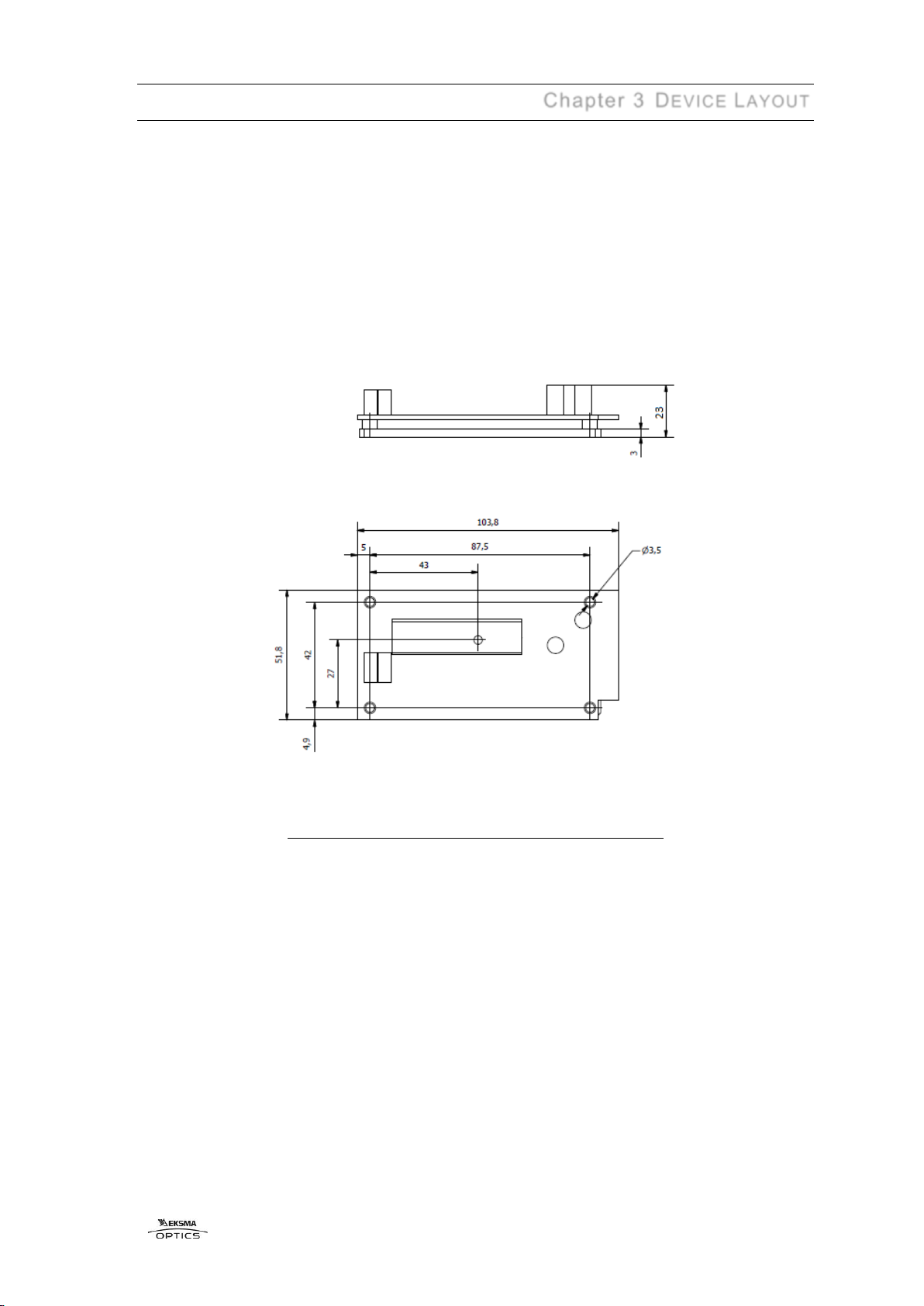
Chapter 3 DEVICE LAYOUT
Figure 1. Outline drawing and dimensions of the driver

4
www.eksmaoptics.com
Figure 2. Top view of the driver
Table 3. Ports seen in top view of the driver
#
Port
1
Connector for DC power suppling and HV driving
1.1
Pin1 SYNC IN input
1.2
Pin2 GND
1.3
Pin3+DC power input
1.4
Pin4 N.C.
1.5
Pin5GND
2.1
HV pulse output pin +OUT
2.2
GND output pin
3.1
+HV Power input pin
3.2
GND input pin from HV supply

5
Chapter 4 SAFETY
Equipment is designed to be safe under normal environmental conditions according to
1.4.1. 61010-1@IEC:2010 (Safety requirements for electrical equipment, control and
laboratory use):
a) indoor use;
b) altitude up to 2000 m;
c) temperature 5ºC to 35˚C;
d) maximum relative humidity 80% for temperatures up to 31ºC decreasing
linearly to 50% relative humidity at 35ºC;
e) POLLUTION degree 1: no POLLUTION or only dry, non-conductive
POLLUTTION occurs.
Warning:
The safety of the system incorporating driver and HV power supply is the
responsibility of the assembler of the system.
Operating the driver is allowed to persons acquainted with the operation manual and
having permission to deal with voltages over 1000 V.
Do not remove unit covers while power cable is connected to the mains (if applicable).
Do not touch any parts of the system when high voltage is applied, as it may cause
human injuries or death.
Do not operate the unit until it is grounded and the load is connected.
Do not use the unit if any defects have been detected.

6
www.eksmaoptics.com
Chapter 5 QUICK START GUIDE
1. Set-up cooling
This driver is cooled by attaching the base plate to a large enough heat sink. The
cooling should ensure the base plate temperature does not exceed 35°C during
operation. The power to be removed by cooling is equal to HV power supply power
consumption.
The driver is attached to a heat sink via the copper base plate. When using an
external heat sink to cool the driver, apply thermal paste between the driver base
plate and heat sink.
2. Connect wires to the Pockels cell
There are several requirements for the wires leading from outputs OUT and GND
to the Pockels cell.
The wires must be about 0.24 mm2 CSA. Both wires must be as short as possible
and of equal length. Their length must not exceed 100 mm. The hot wire must be
at least 5 mm away from any conductive materials (including the operator’s fingers
and instruments) –this is done to avoid any additional capacitive load. Otherwise,
the driver’s characteristics may degrade and/or the driver may get damaged.
3. Ground the Pockels cell driver together with the generator and HV supply
The driver output of several kilovolts (kV) with very fast edges is a powerful source
of electromagnetic interference (EMI). Please ensure proper wiring and grounding
to avoid problems caused by interference.
The best solution to minimize EMI is to mount the driver and the HV power supply
on the metal body of the laser. The driver base plate must have very good contact
with the ground wire of the HV power supply, such as the four mounting holes on
the edges of the board.
If the EMI level is still very high, attempt mounting ferrites on all power and control
wires leading to the driver and power supply (except wires to the Pockels cell).
Please note that the aluminum case of the driver is not designed to provide effective
EMI shielding. Essentially, correct wiring provides best results.
4. Supply voltage to the driver from the DC power supply
For a safe start of the driver, the DC power supply must provide at least 0.6 A peak
current when turning on. Although most DC power supplies are capable of providing
this, it is recommended to double-check your supply as an insufficient peak current
may damage the driver.
5. Supply voltage from the HV supply
If the HV power supply is manufactured by another manufacturer, ensure that there
is no overvoltage while turning it on before supplying voltage.
6. Provide synchronization pulses from the generator
It is necessary to measure the generator output voltage with a 50 load before
applying synchronization signals to the DQ-100-4 driver. The signal voltage must
be in the range of 3.5…5 V.

7
After the generator output voltage is measured, remove the 50 load and provide
synchronization pulses to the driver.
Figure 3. Input circuit of driver
Figure 4. Control timing charts

8
www.eksmaoptics.com
Chapter 6 IMPORTANT NOTES
Please read these important notes before using the product!
1. The output pulse is provided between OUT and GND connectors. Do not connect
an oscilloscope or any other device to the OUT connector. The wire contact with the
Pockels cell must be proper in order to avoid a discharge, which may to damage the
driver.
2. The pulseshape (including fronts) can bemeasured indirectly.On your oscilloscope,
select 1 V sensitivity and the 1 Minput. Then the isolated 1:10 divider should be
slowly and carefully moved towards the hot output wire. When the probe is ~10 mm
away from the hot output wire, the pulse shape should appear in the oscilloscope
(amplitude should be several volts). Do not place the probe too close to the hot output
wire –a discharge may start and damage the driver. This measurement method is not
suitable for measuring >500 ns pulses.
3. Do not attempt to measure the parameters of any parts of the driver’s electronics
using an oscilloscope, especially when the driver is running in pulsed mode. Attempts
to measure parameters of certain parts of the driver’s circuitry may lead to damage.
Table of contents
Popular DC Drive manuals by other brands


Danfoss
Danfoss VLT 5000 Series manual

D+H
D+H SHD 54/450-V Original instructions

GE
GE AF-600 FP Series operating instructions

Intelligent Motion Systems
Intelligent Motion Systems IM805 operating instructions

Conrad
Conrad 57 00 56 operating instructions

Applied Motion Products
Applied Motion Products STR2M Hardware manual


