Intelligent Motion Systems IM805 User manual

intelligent motion systems, inc.
Excellence in MotionTM
IM805
HIGH PERFORMANCE MICROSTEPPING DRIVE
STANDARD DRIVER
CONNECTOR OPTIONS
COOLING SOLUTIONS
ACCESSORIES
OPERATING INSTRUCTIONS
370 N. MAIN ST., PO BOX 457, MARLBOROUGH, CT 06447
PH. (860) 295-6102, FAX (860) 295-6107
Internet: http://www.imshome.com, E-Mail: [email protected]

© Intelligent Motion Systems, Inc.
All Rights Reserved
IM805 Operating Instructions
Revision R032306
The information in this book has been carefully checked and is believed to be
accurate; however, no responsibility is assumed for inaccuracies.
Intelligent Motion Systems, Inc., reserves the right to make changes without
further notice to any products herein to improve reliability, function or design.
Intelligent Motion Systems, Inc., does not assume any liability arising out of
the application or use of any product or circuit described herein; neither does it
convey any license under its patent rights of others. Intelligent Motion Systems
and are trademarks of Intelligent Motion Systems, Inc.
Intelligent Motion Systems, Inc.’s general policy does not recommend the use of
its products in life support or aircraft applications wherein a failure or malfunction
of the product may directly threaten life or injury. Per Intelligent Motion Systems,
Inc.’s terms and conditions of sales, the user of Intelligent Motion Systems, Inc.,
products in life support or aircraft applications assumes all risks of such use and
indemnies Intelligent Motion Systems, Inc., against all damages.
Change Log
Date Revision Changes
03/23/2006 R032306 Updated IMS Contact info, warranty and disclaimer info on cover.
Added sub-section for status indicator LED, pg 12. Updated recom-
mended IMS Motor Part Numbers, pg 27.

1IM805 Operating Instructions Revision R032306
Table of Contents
Introduction............................................................................................... 5
The IM805 ..................................................................................................................... 5
Features and Benets ................................................................................................... 5
The Product Manual ...................................................................................................... 6
Notes and Warnings...................................................................................................... 7
Hardware Specications........................................................................... 8
Section Overview .......................................................................................................... 8
Mechanical Specications ............................................................................................. 8
Electrical Specications................................................................................................. 9
Thermal Specications ................................................................................................ 10
Pin Assignment and Description ................................................................................. 10
Status Indications ........................................................................................................ 12
Mounting The IM805 .............................................................................. 13
Theory of Operation ............................................................................... 15
Section Overview ........................................................................................................ 15
Circuit Operation ......................................................................................................... 15
Microstep Select (MSEL) Inputs.................................................................................. 16
Stepping ...................................................................................................................... 16
Dual PWM Circuit ........................................................................................................ 17
Fullstep Output Signal ................................................................................................. 18
Timing.......................................................................................................................... 18
Power Supply Requirements.................................................................. 19
Section Overview ........................................................................................................ 19
Selecting a Power Supply ........................................................................................... 19
Selecting an Opto Supply............................................................................................ 21
Recommended Wiring................................................................................................. 22
AC Line Filtering.......................................................................................................... 23
Motor Requirements............................................................................... 24
Section Overview ........................................................................................................ 24
Selecting a Motor ........................................................................................................ 24
Motor Wiring ................................................................................................................ 29
Connecting the Motor .................................................................................................. 29
Interfacing and Controlling the IM805 .................................................... 33
Section Overview ........................................................................................................ 33
Layout and Interface Guidelines.................................................................................. 33
Motor Power Connection (+V)..................................................................................... 34
Conguring and Controlling the Output Current .......................................................... 35
Controlling the Output Resolution ............................................................................... 40
Interfacing and Using the Isolated Logic Inputs .......................................................... 42
Connecting and Using the Fault Output ...................................................................... 48
Full Step Output .......................................................................................................... 49
Minimum Connections................................................................................................. 50
Troubleshooting...................................................................................... 51
Section Overview ........................................................................................................ 51
Basic Troubleshooting................................................................................................. 51
Problem Symptoms and Possible Causes .................................................................. 51
Contacting Technical Support ..................................................................................... 54
The IMS Web Site ....................................................................................................... 54
Returning Your Product to IMS ................................................................................... 54

2 IM805 Operating Instructions Revision R032306
3IM805 Operating Instructions Revision R032306
Standard Connection Options ................................................................ 55
Appendix Overview ..................................................................................................... 55
IM805-34P1................................................................................................................. 56
IM805-8P2................................................................................................................... 61
IM805-34P1-8P2 ......................................................................................................... 62
IM805-PLG .................................................................................................................. 63
Cooling Solutions ................................................................................... 65
H-4X Heat Sink Kit ...................................................................................................... 65
Thermal Non-Isolating Pad (TN-48) ........................................................................... 65
Accessories ............................................................................................ 66
Appendix Overview ..................................................................................................... 66
U3-CLP: Side-Mounting Clip ....................................................................................... 66
BB-34-4P Breakout Board........................................................................................... 68
PLG-R Removable Screw Terminal Set...................................................................... 70

2 IM805 Operating Instructions Revision R032306
3IM805 Operating Instructions Revision R032306
List Of Figures
Figure 2.1 IM805 Dimensions .................................................................................. 8
Figure 2.2 IM805 Pin Conguration ....................................................................... 10
Figure 2.3 Stautus Indicator LED........................................................................... 12
Figure 3.1 Mounting Recommendations ................................................................ 13
Figure 4.1 IM805 Block Diagram ........................................................................... 15
Figure 4.2 Recirculating PWM ............................................................................... 17
Figure 4.3 Non-Recirculating PWM ....................................................................... 17
Figure 6.1 Per Phase Winding Inductance ............................................................ 26
Figure 6.2 8 Lead Motor Series Connections ........................................................ 30
Figure 6.3 8 Lead Motor Parallel Connections....................................................... 30
Figure 6.4 6 Lead Motor Half Coil (Higher Speed) Connections ........................... 31
Figure 6.5 6 Lead Motor Full Coil (Higher Torque) Connections ........................... 31
Figure 6.6 4 Lead motor Connections.................................................................... 32
Figure 7.1 IM805 Motor Power Connctions ........................................................... 35
Figure 7.2 Current Adjust Resistor Placement....................................................... 38
Figure 7.3 Current Reduction Adjust Resistor Placement ..................................... 39
Figure 7.4 MSEL Switch Showing 50 Microsteps/Step Selected........................... 40
Figure 7.5 Optically Isolated Inputs........................................................................ 42
Figure 7.6 Switch Interface .................................................................................... 45
Figure 7.7 Open Collector Interface....................................................................... 46
Figure 7.8 TTL Interface ........................................................................................ 46
Figure 7.9 LYNX Interface ..................................................................................... 47
Figure 7.10 The Fault Output Connected to an LED ............................................... 48
Figure 7.11 The Full Step Output Connected to an Up/Down Counter ................... 49
Figure 7.12 IM805 Minimum Connections ............................................................... 50
Figure A.1 IM805-34P1 Connector P1 Mechanical Drawing.................................. 56
Figure A.2 IM805-34P1 Connector P1 Pin Locations ............................................ 56
FIgure A.3 MSEL Connection Using TTL Interface ................................................ 59
Figure A.4 Cascading IM805-34P1 Drives Using the Step/Direction Outputs ....... 60
Figure A.5 IM805-8P2 - Connector P1 ................................................................... 61
Figure A.6 IM805-8P2 - Connector P2 ................................................................... 61
Figure A.7 IM805-34P1-8P2 - Connector P1 ......................................................... 63
Figure A.8 IM805-34P1-8P2 - Connector P2 ......................................................... 63
Figure A.9 IM805-PLG Connectors ........................................................................ 65
Figure A.10 IM805-PLG Pin Location and Orientation............................................. 66
Figure B.1 H-4X Heat Sink ..................................................................................... 67
Figure C.1 U3-CLP Mounting Hole Locations ........................................................ 68
Figure C.2 Attaching the U3-CLP to the IM805 ...................................................... 69
Figure C.3 Panal Mounting an IM805 Using the U3-CLP Clip Set ......................... 69
Figure C.4 BB-34-4P Breakout Board Mechanical Specications.......................... 70
Figure C.5 BB-34-4P Pin Locations........................................................................ 71
Figure C.6 BB-34-4P Mounting Diagram................................................................ 71

4 IM805 Operating Instructions Revision R032306
5IM805 Operating Instructions Revision R032306
List Of Tables
Table 2.1 Electrical Specications .......................................................................... 9
Table 2.2 IM805 Thermal Specications .............................................................. 10
Table 2.3 Connector P1 - Pin Assignment and Description.................................. 11
Table 2.4 Connector P2 - Pin Assignment and Description.................................. 12
Table 3.1 IM805 Mounting Screw/Washer Requirements ................................... 14
Table 5.1 Motor Power Supply Requirements ...................................................... 20
Table 5.2 +5 VDC Power Supply Requirements .................................................. 21
Table 7.1 Current Adjust Resistor Values............................................................. 38
Table 7.2 Microstep Resolution Switch Settings................................................... 41
Table 7.3 Recommended Input Current Limiting Resistor Values........................ 43
Table 7.4 Logic Input Timing ................................................................................ 44
Table A.1 IM805-34P1 - Connector P1 Pin Assignment and Description ............ 57

4 IM805 Operating Instructions Revision R032306
5IM805 Operating Instructions Revision R032306
Features and Benefits
n Low Cost.
n Small Size 2.75” x 3.00” x 1.20”
(69.9 x 76.2 x 30.5 mm).
n Advanced Surface Mount and ASIC Technology.
n High Input Voltage (+24 to +75VDC).
n High Output Current (5A RMS, 7A Peak).
n No Minimum Inductance.
n FAULT Output.
n Optically Isolated Inputs.
Section 1
Introduction
The IM805
The IM805 is a high performance,
yet low cost microstepping driver
that utilizes surface mount ASIC
technology. The IM805 is small,
easy to interface and use, yet
powerful enough to handle the
most demanding applications.
The IM805 has 14 built-in mic-
rostep resolutions (both binary
and decimal). The resolution can
be changed at any time without
the need to reset the driver. This
feature allows the user to rapidly
move long distances, yet precisely position the motor at the end of travel without
the expense of high performance controllers.
With the development of proprietary and patented circuits, ripple current has
been minimized to reduce motor heating common with other designs, allow-
ing the use of low inductance motors to improve high speed performance and
system efciency.
The IM805, because of its small size and low cost, can be used to increase
accuracy and smoothness in systems using higher step angle motors. In many
instances mechanical gearing can be replaced with microstepping, reducing
cost and eliminating potential maintenance.
Available as options for the IM805 are a variety of connector styles, a heat sink
and thermal pad.
The IM805 was developed to provide designers with affordable, state-of-the-art tech-
nology for the competitive edge needed in today’s market.

6 IM805 Operating Instructions Revision R032306
7IM805 Operating Instructions Revision R032306
n Single Supply.
n Up to 10MHz Step Clock Rate.
n Short Circuit Protection.
n Microstep Resolution to 51,200 Steps/Rev.
n Microstep Resolutions can be Changed “On-The-Fly” With-
out Loss of Motor Position.
n 20 kHz Chopping Rate.
n Automatically Switches Between Slow and Fast Decay for
Unmatched Performance.
n 14 Selectable Resolutions Both in Decimal and Binary.
n Adjustable Automatic Current Reduction.
n At Full Step Output.
The Product Manual
The main sections of this manual address the standard IM805 driver, which
come with 8 position screw terminals as a connection medium. The different
connector, input options and accessories are covered in detail in the appendices.
The Bookmarks
The IB Series product manual in it’s electronic format (ib.pdf) can be down-
loaded from the IMS website at www.imshome.com. This version includes a
Bookmark feature that allows the reader to link from a Bookmarked Topic in
the Table of Contents to a full description of that feature’s
attributes and functions. You can also select a Topic directly
from the Table of Contents Pages. Topics with a Bookmark
function are further identiable because the cursor changes
from a normal pointer to a “nger” pointer when placed over
the word.

6 IM805 Operating Instructions Revision R032306
7IM805 Operating Instructions Revision R032306
WARNING! The IM805 components are sensitive to ElectroStatic
Discharge (ESD). All handling should be done at an ESD protected
workstation.
WARNING! Hazardous voltage levels may be present if using an
open frame power supply to power the IM805.
WARNING! Ensure that the power supply output voltage does not
exceed the maximum input voltage of the IM805.
WARNING! A current adjustment resistor is always necessary to
keep the Driver and/or Motor in a safe operating range.
DO NOT operate the IM805 Driver without a current adjustment
resistor in place.
Notes and Warnings
WARNING! Turn off the AC power side to power down the DC
power supply.
WARNING! For battery operated systems connect a “transient
suppressor” across the power switch to prevent arcs and high
voltage spikes. Also place a “transorb” across the +V and GND of
the battery connections at the Driver.

8 IM805 Operating Instructions Revision R032306
9IM805 Operating Instructions Revision R032306
0.150
(3.8)
2.600
(66.0)
2.750
(69.9)
0.290
(7.4)
2.710
(68.8)
3.000
(76.2)
4X Ø 0.160
(4X Ø 4.1)
0.410
(10.4)
17
34
1
0.025
(0.6)
18
12345678
1.00
(25.4)
0.312
(7.92)
0.030
(0.8)
1.320
(33.53)
IM805-34P1
Section 2
Hardware Specifications
Section Overview
This section will acquaint you with the dimensional information, pin de-
scription, power, environmental and thermal requirements of the IM805.
It is broken down as follows:
n Mechanical Specications.
n Electrical Specications.
n Thermal Specications.
n Pin Assignment and Description.
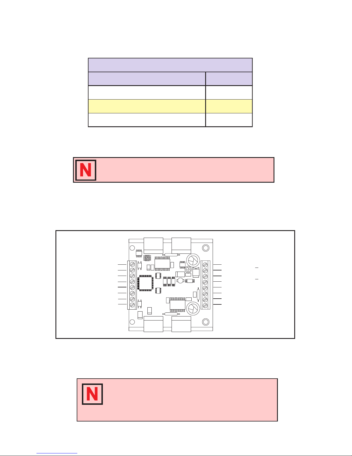
Mechanical Specifications
Shown are the standard 8 position screw terminal set and the Optional 34
Pin Connector for the IM805. Specications for the 34 Pin Connector are
available in Appendix A: Standard Connection Options, of this document.
Dimensions are in inches, parenthesis dimensions are in millimeters.
Figure 2.1: IM805 Dimensions

8 IM805 Operating Instructions Revision R032306
9IM805 Operating Instructions Revision R032306
Electrical Specifications
Test Condition: TA=25°C, +V=75VDC
Table 2.1: IM805 Electrical Specications
* Includes motor back EMF.
**Lower currents may be used for current reduction.
Ω
10 IM805 Operating Instructions Revision R032306
11IM805 Operating Instructions Revision R032306
Thermal Specifications
Table 2.2: IM805 Thermal Specications
NOTE! Additional cooling may be required to limit the plate
temperature to 70°C! An optional heat sink and thermal pad is
available, see Appendix C: Cooling Solutions for details.
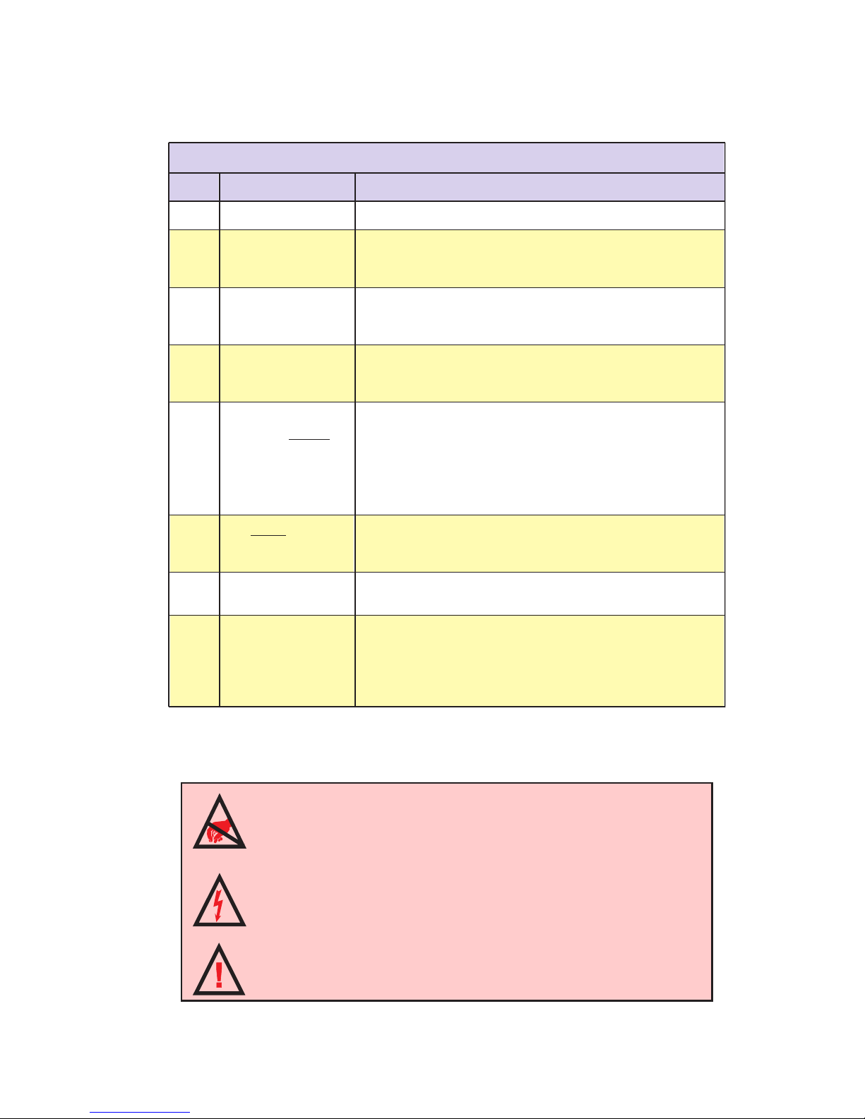
Pin Assignment and Description
Figure 2.2: IM805 Pin Conguration
NOTE! This pin conguration diagram and table represent
the pinout of any 8 position connector used for P1. If you
purchased the IM805-34P1 option (34 Position Header) the
pin conguration diagram and table is located in Appendix A:
Standard Connection Options.
N/C - P1:1 P2:8 - Motor ØA
P2:6 - Motor ØB
P2:5 - Motor ØB
P2:4 - +V (+12 to +48 VDC)
P2:3 - GND
P2:2 - Current Adjust
P2:1 - Current Reduction Adjust
P2:7 - Motor ØA
Step Clock - P1:2
Direction - P1:3
Opto Supply - P1:4
Enable - P1:5
Reset - P1:6
Fault Output - P1:7
On-Full-Step Output - P1:8
10 IM805 Operating Instructions Revision R032306
11IM805 Operating Instructions Revision R032306
Connector P1
Table 2.3: Connector P1 - Pin Assignment and Descriptions
WARNING! The IM805 components are sensitive to ElectroStatic
Discharge (ESD). All handling should be done at an ESD protected
workstation.
WARNING! Hazardous voltage levels may be present if using an
open frame power supply to power the IM805.
WARNING! Ensure that the power supply output voltage does not
exceed the maximum input voltage of the IM805.
12 IM805 Operating Instructions Revision R032306
13IM805 Operating Instructions Revision R032306
Connector P2
Table 2.4: Connector P2 - Pin Assignment and Descriptions
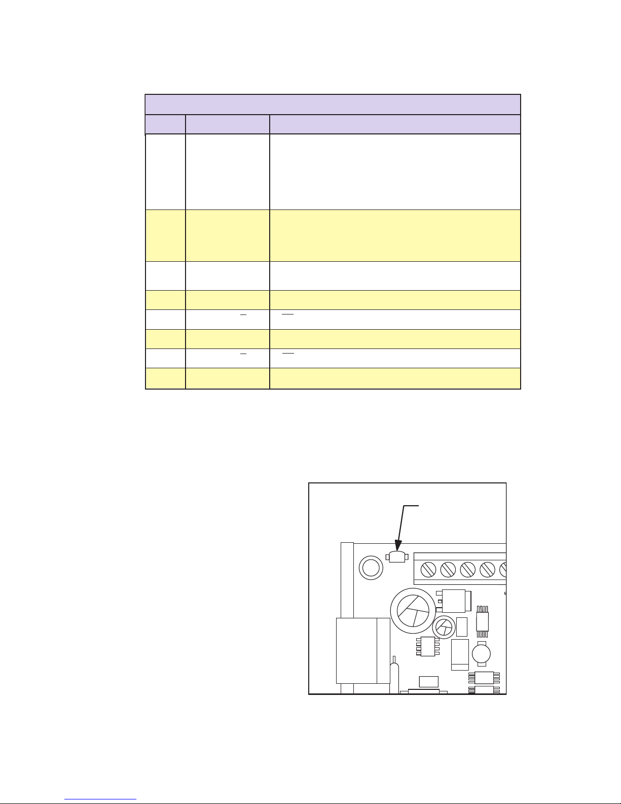
Status Indicators
Green: Power On
Red: Fault
Figure 2.3: Status Indicator LED
The IM805 features a two-
color LED mounted to the
left of connector P2 for status
indication.
When the drive is powered
and operating normally, the
LED will be green. When in
a fault condition, the LED
will be red.

12 IM805 Operating Instructions Revision R032306
13IM805 Operating Instructions Revision R032306
Section 3
Mounting The IM805
This section has recommended mounting instructions for the standard
IM805. For additional connector options for the IM805 see Appendix A:
Standard Connection Options, of this document. An optional heat sink
and thermal pad, the H-4X and TN-48, are available for the IM805. See
Appendix C: Cooling Solutions, for details.
The IM805 has limited available clearance for mounting screws. If a
mounting screw has a head diameter greater than 0.230 inches (5.8
mm), an insulating washer MUST be used to maintain proper electrical
isolation between the mounting screw and the IM805’s components. The
washer must have a minimum thickness of 0.060 inches (1.52 mm) and
a maximum diameter of 0.270 inches (6.86 mm). See Table 3.1 for screw
recommendations/washer requirements.
Thermal Pad
TN-48 or Equivalent
Mounting Plate
or Heat Sink Surface
4 X #6 (M3) Threaded
Holes. (See Mechanical,
Figure 2.1 for Hole Pattern
Dimensions) The torque specification
for the mounting screws
is 5.0 to 7.0 lb-in (0.60 to
0.80 N-m). Do not over-
tighten screws!
12345678
See Table 3.1 for
Mounting Hardware
Requirements
Figure 3.1: Mounting Recommendations

14 IM805 Operating Instructions Revision R032306
15IM805 Operating Instructions Revision R032306
Table 3.1: IM805 Mounting Screw/Washer Requirements
WARNING! Use of any mounting hardware other than that
recommended may result in damage to the driver circuitry! Use
ONLY the hardware recommended by this document to mount
the IM805 to your panel or heat sink plate!
The following insulating washers (listed by vendor and part #) are suit-
able for use in mounting the IM805:
n Accurate Screw Machine Co.
P/N 88-.062 N
n Micro Plastics, Inc.
P/N 17W02504
n Seastrom Manufacturing
P/N 5610-250-62
14 IM805 Operating Instructions Revision R032306
15IM805 Operating Instructions Revision R032306
Section 4
Theory of Operation
Section Overview
This section will cover the circuit operation for the IM805 microstepping
driver.
n Circuit Operation.
n Microstep Select Inputs.
n Stepping.
n Dual PWM Circuit.
n Fullstep Output.
n Timing.
Circuit Operation
Microstepping drives have a much higher degree of suitability for ap-
plications that require smooth operation and accurate positioning at low
speeds than do half/fullstep drivers and reduction gearing. The IM805,
which can be set to microstep resolutions as high as 51,200 microsteps/rev
(256 microsteps/step) using a 1.8° stepping motor, is ideal for such appli-
cations.
In order to subdivide motor steps into microsteps while maintaining
positional accuracy, precise current control is required. The IM805 ac-
complishes this by the use of a unique Dual PWM circuit built into the
patented IM2000 Microstep Controller ASIC, which resides at the heart of
the IM805. This PWM circuit uses alternating recirculating/non-recircu-
lating modes to accurately regulate the current in the windings of a two
phase stepping motor.
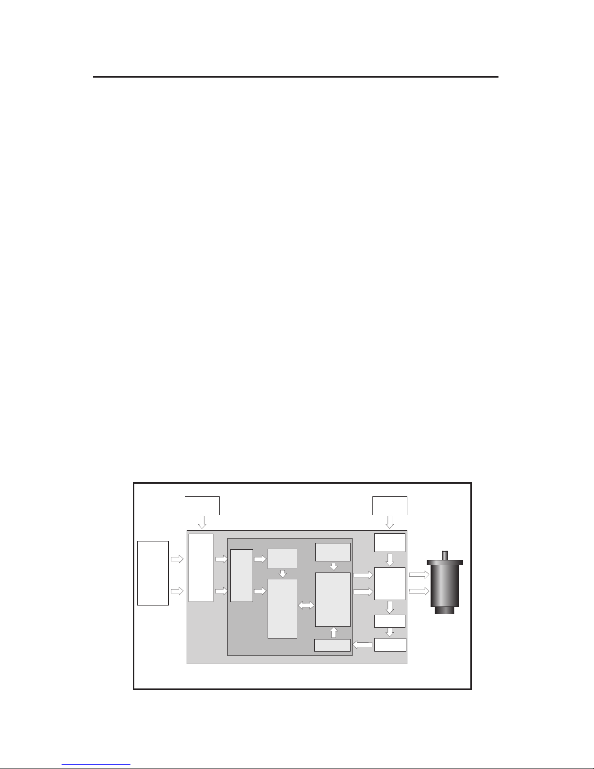
Figure 4.1: IM805 Block Diagram
INPUT
LOGIC
INPUT
LOGIC
ISOLATION
CIRCUITRY
SINE/COSINE
POSITION
GENERATOR
MICROSTEP
RESOLUTION
SELECTION
STEP CLOCK
DIRECTION
ENABLE
RESET
CURRENT
CONTROL
USER
INTERFACE
POWER
SUPPLY
OPTO
SUPPLY
20kHz CHOP.
OSC
PROTECTION
CIRCUIT
IM2000 MICROSTEP
CONTROLLER
IM805 MICROSTEPPING DRIVER
PHASE A/B
OUTPUT
CIRCUITRY
CURRENT
SENSING
STEPPING
MOTOR
SHORT
CIRCUIT
PROTECTION
OVER CURRENT
PROTECTION

16 IM805 Operating Instructions Revision R032306
17IM805 Operating Instructions Revision R032306
Microstep Select (MSEL) Inputs
Another unique feature of the IM2000 is the ability to change resolutions
at any time. A resolution change can occur whether the motor is being
clocked or is at rest. The change will not take place until the rising edge
of the next step clock input. At this time, the new resolution is latched
and implemented before the step clock pulse takes effect.
If a resolution is chosen such that the sine/cosine output of the IM2000
would not land on an electrical fullstep of the motor, then the IM2000
will automatically align itself to the full step position on the step clock
pulse that would have caused the motor to rotate past the full step. The
step clock pulses, from that point forward, will be equal to the selected
resolution. This feature allows the user to switch resolutions at any time
without having to keep track of sine/cosine location. Because of this, the
On-Full-Step output of the IM805 can easily be used to monitor position.
Conguration settings for the Microstep Resolution are located in Section
7 of this document, Interfacing and Controlling the IM805.
Stepping
The IM2000 contains a built-in sine/cosine generator used for the genera-
tion of Phase A and Phase B position reference. This digitally encoded
9 bit sine and 9 bit cosine signal is directly fed into a digital to analog
converter.
The step clock (SCLK) and direction (DIR) inputs are buffered using
Schmidt triggered buffers for increased noise immunity and are used to
increment or decrement the sine/cosine position generator. The position
generator is updated on the rising edge of the step clock input. It will
increment or decrement by the amount specied by the microstep resolu-
tion select (MSEL) inputs.
The direction (DIR) input determines the direction of the position genera-
tor and hence the direction of the motor. The DIR input is synchronized
to the SCLK input. On the rising edge of the SCLK input the state of the
DIR input is latched in. The position generator will then look to see if
there has been a change in direction and implement that change be-
fore executing the next step. By utilizing this method to implement the
direction change, the noise immunity is greatly increased and no physical
change in the motor occurs if the direction line is toggled prior to the
step clock input.
The enable/disable input does not affect the step clock input. The sine/
cosine generator will continue to update if a signal is applied to the step
clock input.
The IM2000 outputs both sine and cosine data simultaneously when
applying a step clock input. Dual internal look-up tables are used to
output a unique position for every step clock input to enhance system
performance.

16 IM805 Operating Instructions Revision R032306
17IM805 Operating Instructions Revision R032306
Dual PWM Circuit
The IM2000 contains a unique dual PWM circuit that efciently and accu-
rately regulates the current in the windings of a two phase stepping motor.
The internal PWM accomplishes this by using an alternating recirculating/
non-recirculating mode to control the current.
Recirculating
In a recirculating PWM, the cur-
rent in the windings is contained
within the output bridge while
the PWM is in its OFF state. (After
the set current is reached.) This
method of controlling the current
is efcient when using low induc-
tance motors, but lacks response
because of its inability to remove
current from the windings on the
downward cycle of the sine/
cosine wave (See Figure 4.1).
Non-Recirculating
In a non-recirculating PWM, the
current ows up through the bridge and back to the supply in the OFF
phase of the cycle. This method of controlling current allows for much
better response but reduces efciency and increases current ripple, espe-
cially in lower inductance motors (See Figure 4.3).
The IM2000’s PWM utilizes the best features of both by combining recir-
culating and non-recirculating current control. On the rising edge of the sine/
cosine waveform, the PWM will
always be in a recirculating mode.
This mode allows the driver to
run at peak efciency while main-
taining minimum current ripple
even with low inductance motors.
On the downward cycle of the
sine/cosine waveform, the PWM
operates in a two part cycle. In
the rst part of its cycle, the PWM
is in a non-recirculating mode
to pull current from the motor
windings. In the second part of
the cycle the PWM reverts back
to recirculating mode to increase
efciency and reduce current
ripple.
Figure 4.3: Non-Recirculating PWM
DRIVE CURRENT
RECIRCULATION
Figure 4.2: Recirculating PWM
DRIVE CURRENT
RECIRCULATION

18 IM805 Operating Instructions Revision R032306
19IM805 Operating Instructions Revision R032306
The IM2000 will automatically change the non-recirculating pulse widths
to compensate for changes in supply voltage and accommodate a wide
variety of motor inductances. This method also allows for the use of very
low inductance motors with your IM805 driver, while utilizing a 20kHz
chopping rate which reduces motor heating but maintains high efciency
and low current ripple.
Fullstep Output Signal
The fullstep output signal from the IM805 is an active high output at
connector P1:8. This output will be TRUE for the duration of the full
step. A full step occurs when either Phase A or Phase B crosses through
zero (i.e. full current in one motor winding and zero current in the other
winding). This fullstep position is a common position regardless of the
microstep resolution selected.
The fullstep output can be used to count the number of mechanical
fullsteps that the motor has traveled without the need to count the num-
ber of microsteps in between. A controller that utilizes this output can
greatly reduce its position tracking overhead, thus substantially increasing
its throughput.
Interface guidelines and a sample application for the fullstep output are
located in Section 7 of this document, Interfacing and Controlling the
IM805.
Timing
The direction and microstep resolution select inputs are synchronized
with the positive going edge of the step clock input. When the step clock
input goes HIGH, the direction and microstep resolution select inputs are
latched. Further changes to these inputs are ignored until the next rising
edge of the step clock input.
After these signals are latched, the IM805 looks to see if any changes
have occurred to the direction and microstep resolution select inputs. If
a change has occurred, the IM805 will execute the change before taking
the next step. Only AFTER the change has been executed will the step
be taken. If no change has occurred, the IM805 will simply take the next
step. This feature works as an automatic debounce for the direction and
microstep resolution select inputs.
The reset and enable inputs are asynchronous to any input and can be
changed at any time.
Table of contents
Other Intelligent Motion Systems DC Drive manuals


