EKSMA OPTICS HV-200 User manual

HIGH VOLTAGE POWER
SUPPLIES
HV-200
HV-400
HV2-200
Technical Description
Rev. 2202
2022
Lithuania


i
www.eksmaoptics.com
CONTENTS
CHAPTER 1 WARRANTY ..................................................................................................................... 1
1.1. WARRANTY STATEMENT ....................................................................................................................... 1
1.2. SERVICE CONTACT INFORMATION ............................................................................................................ 1
CHAPTER 2 SPECIFICATIONS............................................................................................................... 2
2.1. GENERAL INFORMATION ....................................................................................................................... 2
2.1.1. Models .................................................................................................................................... 2
2.1.2. Main Components ................................................................................................................... 2
2.2. TECHNICAL SPECIFICATIONS ................................................................................................................... 3
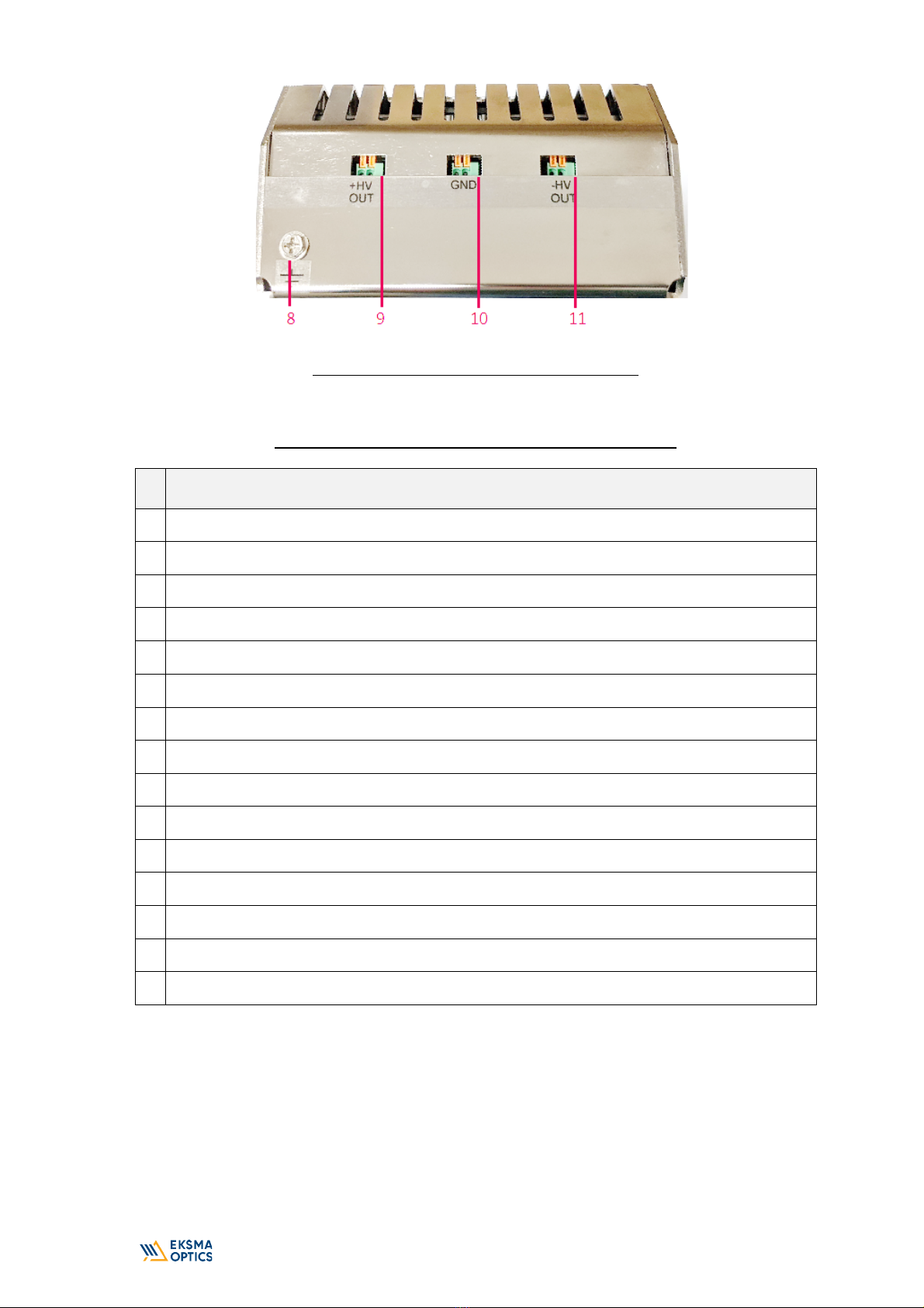
CHAPTER 3 DEVICE LAYOUT ............................................................................................................... 4
CHAPTER 4 SAFETY ............................................................................................................................ 7
CHAPTER 5 QUICK START GUIDE ........................................................................................................ 8
5.1. GROUND THE HV POWER SUPPLY ........................................................................................................... 8
5.2. SUPPLY +48V POWER .......................................................................................................................... 8
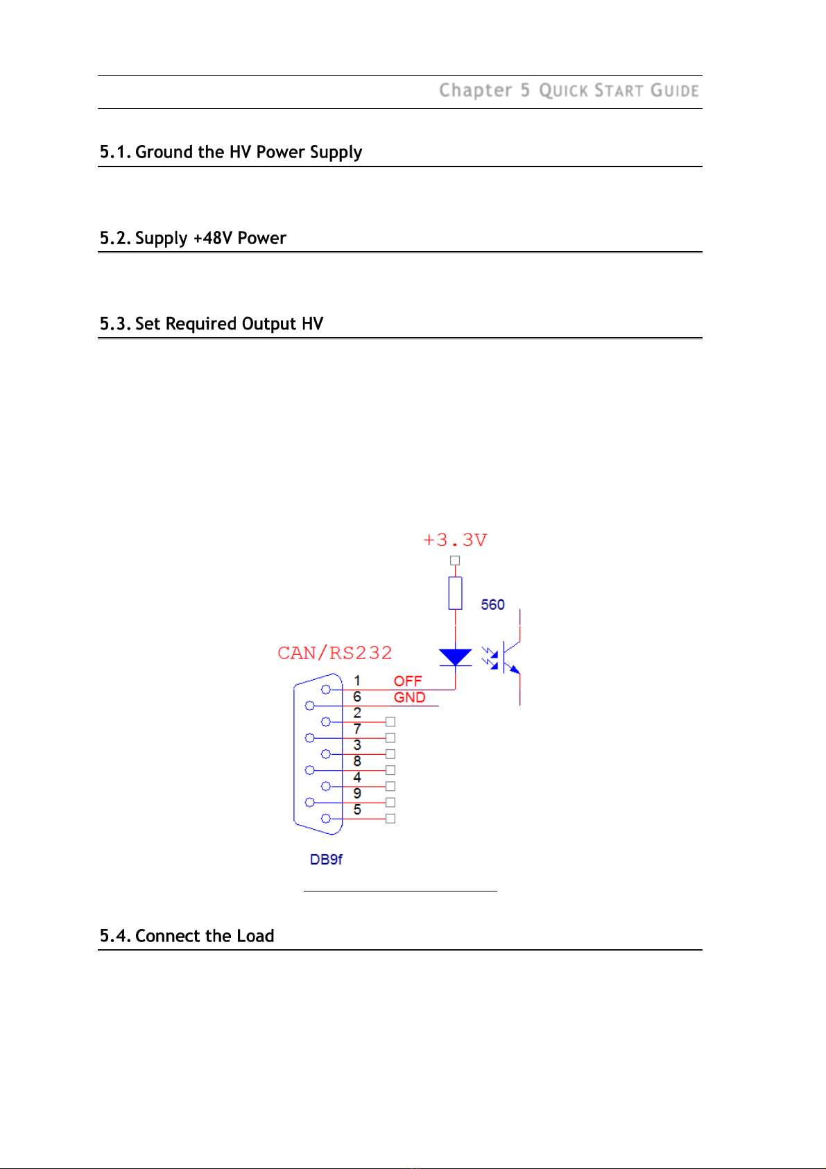
5.3. SET REQUIRED OUTPUT HV ................................................................................................................... 8
5.4. CONNECT THE LOAD ............................................................................................................................ 8
5.5. CHECK THE DC POWER SUPPLY .............................................................................................................. 9
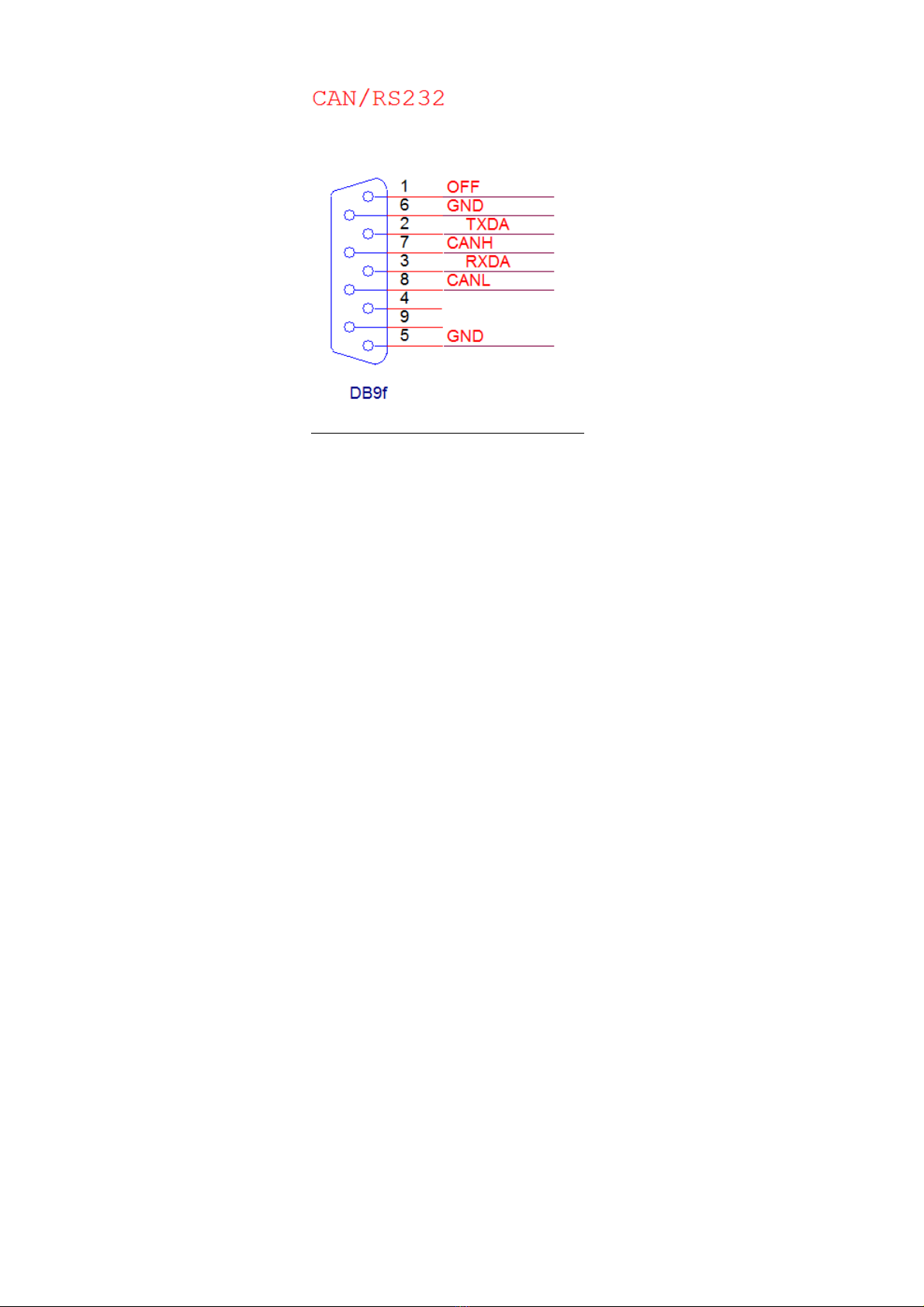
CHAPTER 6 CONTROL VIA CAN/RS232 ............................................................................................. 10
6.1. CAN .............................................................................................................................................. 10
6.2. RS232 ........................................................................................................................................... 10
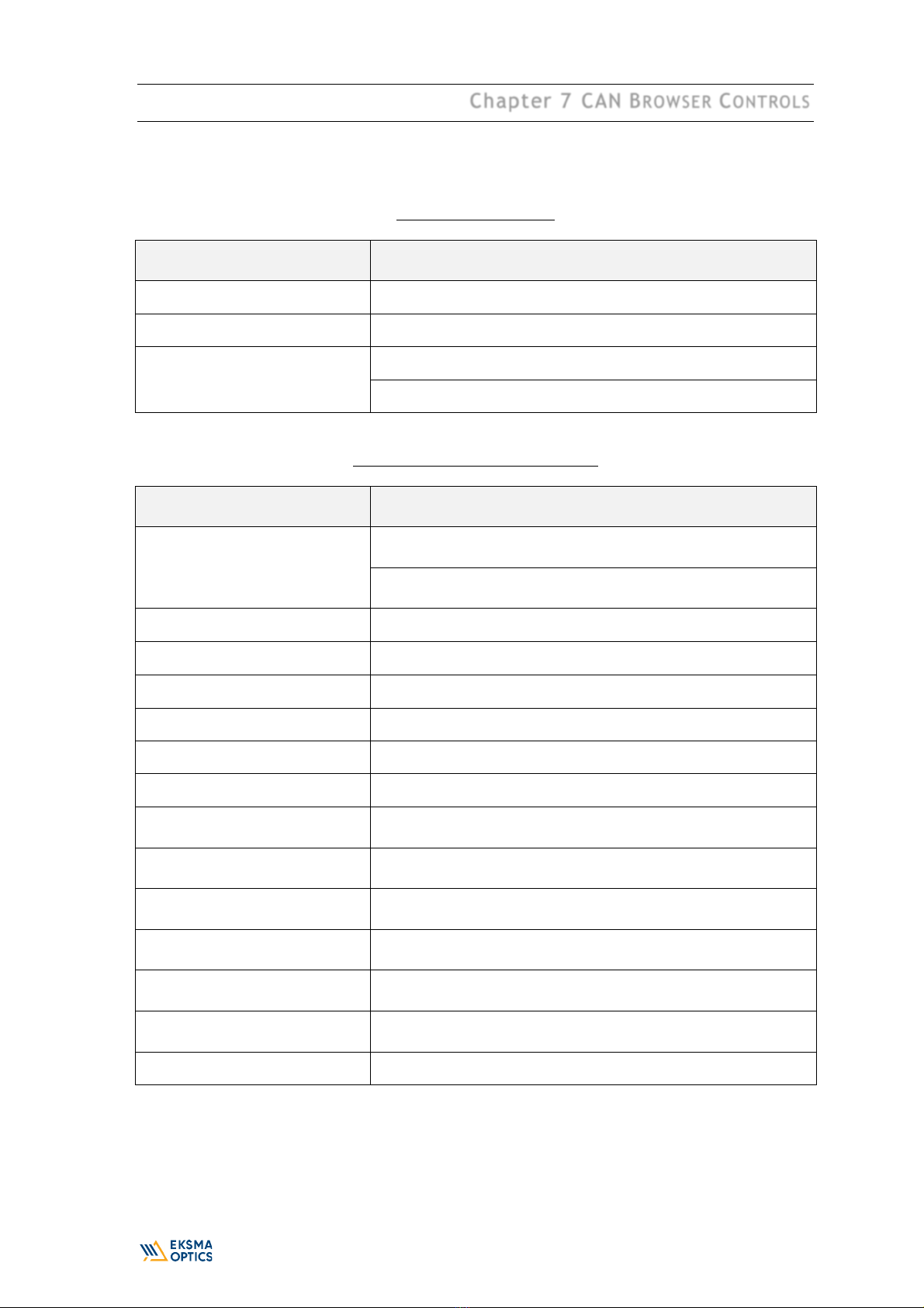
CHAPTER 7 CAN BROWSER CONTROLS ............................................................................................ 11

ii
www.eksmaoptics.com
LIST OF FIGURES
FIGURE 1. OUTLINE DRAWING AND DIMENSIONS OF THE HV POWER SUPPLY ................................................................ 4
FIGURE 2. FRONT CONTROLS OF THE HV POWER SUPPLY ......................................................................................... 4
FIGURE 3. REAR CONTROLS OF THE HV POWER SUPPLY ........................................................................................... 5
FIGURE 4. RS232/CAN CONNECTOR PINOUT ...................................................................................................... 6
FIGURE 5. ON/OFF CONTROL INPUT ................................................................................................................. 8
FIGURE 6. CAN-USB CONVERTER ................................................................................................................... 10
LIST OF TABLES
TABLE 1. MODELS ......................................................................................................................................... 2
TABLE 2. MAIN COMPONENTS .......................................................................................................................... 2
TABLE 3. TECHNICAL SPECIFICATIONS.................................................................................................................. 3
TABLE 4. CONTROLS AND CONNECTIONS OF THE HV POWER SUPPLY ........................................................................... 5
TABLE 5. BASIC CONTROLS ............................................................................................................................. 11
TABLE 6. ADVANCED CONTROL REGISTERS ......................................................................................................... 11

1
www.eksmaoptics.com
Chapter 1
WARRANTY
The HV power supplies are protected by a one-year warranty covering labor and parts. The
warranty enters into validity since the shipment date. Any evidence of improper use or
unauthorized repair attempts voids the warranty.
For service/warranty requests, please contact:
EKSMA OPTICS, UAB
c/o EKSMA Optics, UAB
Dvarcioniu st. 2B
LT-10233 Vilnius, Lithuania
Phone:
Fax.:
E-mail:
Website:
+370 5 272 99 00
+370 5 272 92 99
info@eksmaoptics.com
www.eksmaoptics.com

2
www.eksmaoptics.com
Chapter 2
SPECIFICATIONS
The table below lists standard options. Custom voltage modifications may be delivered on
request.
Table 1. Models
Catalog number
Maximal HV output, kV
Maximal HV current, mA
HV-200-1.8
1.8
110
HV-200-2.6
2.6
76
HV-200-3.6
3.6
55
HV-200-4.0
4.0
45
HV-400-1.8
1.8
220
HV-400-2.6
2.6
152
HV-400-3.6
3.6
110
HV-400-4.0
4.0
90
HV2-200-1.5
±1.5
±133
HV2-200-2.0
±2.0
±100
HV2-200-2.6
±2.6
±76
HV2-200-3.6
±3.6
±55
Table 2. Main components
Component
Quantity
Notes
High voltage (HV) power supply
1
-
Connector for DC input
1
-
+24V cable to Pockels cell driver
1
Optionally, if delivered in set with Pockels
cell driver.
RS232 cable
1
Optionally, if RS232 control is requested
CAN cable
1
Optionally, if CAN control is requested
Technical description
1
-

3
www.eksmaoptics.com
Table 3. Technical specifications
Parameter
Value(s)
HV-200
HV-400
HV2-200
Output voltage polarity
Positive
Bipolar
Maximum HV output power at
maximal output voltage, W
200
400
2×200
Supply voltage DC requirements
47.5…55 V, 4.5 A
47.5…55 V, 9 A
Output voltage ripple, %
< 0.3
Output voltage control
CAN/RS232/Internal potentiometer
Maximum +24V output current, A
1.2
Maximum ambient temperature
for operation, °C
45
Dimensions, mm
See CHAPTER 3 DEVICE LAYOUT.
200×119×76
Weight, g
1120

4
www.eksmaoptics.com
Chapter 3
DEVICE LAYOUT
Figure 1. Outline drawing and dimensions of the HV power supply
Figure 2. Front controls of the HV power supply

5
www.eksmaoptics.com
Figure 3. Rear controls of the HV power supply
Table 4. Controls and connections of the HV power supply
#
Port
1
Potentiometer for HV tuning in potentiometer mode
2
LED HV output on
3
LED +48V
4
+24V auxiliary output connector
5.1
2 pins for +48V input
5.2
2 pins for GND input (-48V)
6.1
Test point for -HV current monitoring (1V = 100mA)
6.2
Test point for +HV current monitoring (1V = 100mA)
6.3
Test point for +HV output monitoring (1V = 1kV)
6.4
Test point GND
7
CAN/RS232 connector
8
Grounding screw
9
+HV output
10
GND output
11
-HV output if equipped.

6
www.eksmaoptics.com
Figure 4. RS232/CAN connector pinout

7
www.eksmaoptics.com
Chapter 4
SAFETY
Equipment is designed to be safe under normal environmental conditions according to 1.4.1.
61010-1@IEC:2010 (Safety requirements for electrical equipment, control and laboratory use):
1. indoor use;
2. altitude up to 2000 m;
3. temperature 5˚C to 35˚C;
4. maximum relative humidity 80% for temperatures up to 31˚C decreasing linearly to 50%
relative humidity at 35˚C;
5. POLLUTION degree 1: no POLLUTION or only dry, non-conductive POLLUTTION occurs.
Warning:
The safety of the system incorporating driver and HV power supply is the
responsibility of the assembler of the system.
Operating the power supply is allowed to persons acquainted with the operation manual and
having permission to deal with voltages over 1000 V.
Do not remove unit covers while power cable is connected to the mains (if applicable).
WARNING
Direct contact with the exposed inner parts of the system when it is powered
may cause human injuries or death.
Do not operate the unit until it is grounded and the load is connected.
Do not use the unit if any defects have been detected.

8
www.eksmaoptics.com
Chapter 5
QUICK START GUIDE
Provide the proper ground connection to ground screw (#8) of HV power supply.
Connect the +48 VDC power supply to the HV power supply. See Table 3 for requirements.
HV level may be tuned by:
1. Using internal (#1) trimmer potentiometer. Output voltage and current control is
available on test point TP OUT connector pins (#6).
2. Using CAN or RS232, see CHAPTER 6 CONTROL VIA CAN/RS232 for details.
3. HV output can be switched off by connecting pin 1 of connector CAN/RS232 (#7) to GND
(pins 5, 6).
Figure 5. ON/OFF control input
Switch the DC power supply off. Connect the load. Check that the connection cables are firmly
attached.

9
www.eksmaoptics.com
Switch the +48 VDC power on. Measure the voltage on +48 VDC input of HV power supply while
HV power supply is loaded.
If the voltage measured is below +47V, use thicker wires, or increase the DC supply voltage to
compensate voltage drop.

10
www.eksmaoptics.com
Chapter 6
CONTROL VIA CAN/RS232
CAN-USB converter is recommended for operation. It can be ordered from Eksma Optics. It
comes together with „CAN Browser“ software and a set of required cables.
Figure 6. CAN-USB converter
1. Connect CAN-USB converter to PC and HV power supply by cables supplied.
2. Turn on +48V power supply.
3. Install and open CAN Browser.
4. Set required settings (see CHAPTER 7 CAN BROWSER ).
1. Connect HV power supply to PC by the RS232 cable supplied. Note: do not attempt using
ordinary RS232 cables. Some of them are not compatible with this series of HV power
supplies.
2. Turn on +48V power supply.
3. Install and open CAN Browser.
4. Set required settings (see CHAPTER 7 CAN BROWSER ).
5. Refer document “ASCII serial protocol description” for details.

11
www.eksmaoptics.com
Chapter 7
CAN BROWSER CONTROLS
Below tables 5 and 6 present list of registers that can be accessed and/or read-out using CAN
Browser.
Table 5. Basic controls
Setting
Description
Command
Toggle the HV supply output ON/OFF
Uset
Set HV output value.
Controller setup/Analog
control
Off – control HV supply via CAN/RS232.
On – control HV supply by potentiometer.
Table 6. Advanced control registers
Setting
Description
External off status
Inactive – pin 1 of connector CAN/RS232 (#7) is not connected
to ground.
Active – pin 1 of connector CAN/RS232 (#7) is connected to
ground. HV power supply output is turned off.
Udisp
Display HV output voltage.
IsensP
Display positive output current of HV supply.
IsensM
Display negative output current of HV supply.
Tpcb
Display PCB temperature of HV supply.
Vpwr
Display input +48 voltage.
Vprog
Display maximal HV value of output for potentiometer mode.
Interlock/Vpwr max
Display actual value of +48V maximal input. If DC input is over
the maximal value (see Table 3), HV power supply turns off.
Interlock/Uout max
Display setting of maximal HV output value. If this value is
exceeded, HV power supply is off.
Interlock/IsenseP max
Display setting of positive output maximal current value. If this
value is exceeded, HV power supply is off.
Interlock/IsenseM max
Display setting of negative output maximal current value. If this
value is exceeded, HV power supply is off.
Interlock/Tpcb max
Display setting of PCB maximal temperature. If this value is
exceeded, HV power supply is off.
Interlock/Tunildm max
Display setting of processor maximal temperature. If this value
is exceeded, HV power supply is off.
Controller setup/Uset limit
Display setting of HV output limit.
This manual suits for next models
14
Table of contents
Other EKSMA OPTICS Power Supply manuals

EKSMA OPTICS
EKSMA OPTICS DPB-10-4.2 User manual

EKSMA OPTICS
EKSMA OPTICS PS-170 User manual

EKSMA OPTICS
EKSMA OPTICS HVS-100 Parts list manual

EKSMA OPTICS
EKSMA OPTICS HV-170-1.8 User manual

EKSMA OPTICS
EKSMA OPTICS PS-80 User manual

EKSMA OPTICS
EKSMA OPTICS PS-40 Parts list manual

EKSMA OPTICS
EKSMA OPTICS PS-120 User manual
Popular Power Supply manuals by other brands

Franke
Franke ZAQUA006 Installation and operating instructions

multicomp pro
multicomp pro MP710079 user manual

Eaton
Eaton GW4-030-BA3 Instruction leaflet

Horizont
Horizont Hotline Hobby Installation guide and warranty

Vertiv
Vertiv 582127200 user manual

Oxford Instruments
Oxford Instruments Andor Shamrock 500i quick start guide