TBB iDU500-24 User manual
iDU series User Manual
TBB Power Co.,Ltd
iDU series
DC POWER SUPPLY
Version: A1.0
Date: Feb.2017
iDU series User Manual
TBB Power Co.,Ltd
WARNING : FIRE HAZARD
SUITABLE FOR MOUNTING ON CONCRETE OR OTHER
NON- COMBUS TIBLE SURFACE ONLY
CAUTION : THE DC AND AC BREAKER MUST HAVE BEEN
TURNED OFF BEFORE SERVICING
MADE IN CHINA

iDU series User Manual
TBB Power Co.,Ltd
D
Di
is
sc
cl
la
ai
im
me
er
r
Unless specially agreed in writing, TBB Power Co.,Ltd
Take no warranty as to the accuracy, sufficiency of suitability of any technical or other
information provided in this manual or other documentation.
Assumes no responsibility or liability for loss or damage, whether direct, indirect,
consequential or incidental, which might arise out of the use of such information.
TBB offer standard warranty with its products, taking no responsibility for direct or indirect
loss due to equipment failure.
A
Ab
bo
ou
ut
t
t
th
hi
is
s
M
Ma
an
nu
ua
al
l
This manual describes our product features and provides procedure of installations. This manual
is for anyone intending to install our equipment.
General Instruction
Thanks for choosing our products and this manual were suitable for iDU series .
This chapter contains important safety and operation instructions. Read and keep this User Guide
well for later reference.
DC power supply needs to be installed by professionals and please pay attention to the following
points prior to installation:
1> Please check the voltage of battery is same to the nominal input voltage of this charger.
2> While connecting wires, please secure the connection and avoid short cut between positive
terminal and negative terminal of battery, which will cause damage of battery.
3> DC power supply will have high voltage inside. Only authorized electrician can open the case.
4> Please check if voltage of battery is same to the nominal DC input voltage of this unit.

iDU series User Manual
TBB Power Co.,Ltd
I
In
nd
de
ex
x
1. General Safety Instruction ............................................................................................................................... 1
1.1 Safety Instruction ...................................................................................................................................... 1
1.2 General Precaution ................................................................................................................................... 1
1.3 Precaution regarding battery operation ................................................................................................ 1
2. Introduction ........................................................................................................................................................ 2
2.1 Schematic Diagram ................................................................................................................................... 2
2.2 Charging Curve ......................................................................................................................................... 3
2.3 Mode Name ............................................................................................................................................... 3
3
3.
. Structure .............................................................................................................................................................. 4
4.
O
Op
pe
er
ra
at
ti
io
on
n............................................................................................................................................................. 5
4.1 Wiring diagram ......................................................................................................................................... 5
4.2 Port definitions .......................................................................................................................................... 5
4.3 Buttons and LED indicator ...................................................................................................................... 6
5
5.
.
S
Sp
pe
ec
ci
if
fi
ic
ca
at
ti
io
on
n ....................................................................................................................................................... 7

iDU series User Manual
TBB Power Co.,Ltd 1
1. General Safety Instruction
1.1 Safety Instruction
As dangerous voltage and high temperature exist within the charge controller, only qualified and
authorized maintenance personnel are permitted to open and repair it.
This manual contains information concerning the installation and operation of the charge
controller. All relevant parts of the manual should be read prior to commencing the installation.
Please follow the local stipulation meantime.
Any operation against safety requirement or against design, manufacture, safety standard, and are
out of the manufacturer warranty.
1.2 General Precaution
1.2.1 Do not expose to rain, snow or liquids of any type,it is designed for indoor use.
1.2.2 To avoid fire and electric shock, make sure all cables selected with right gauge and being
connected well. Smaller diameter and broken cable are not allowed to use.
1.2.3 Please do not put any inflammable goods near to charge controller.
1.2.4 Never place unit directly above batteries, gases from a battery will corrode and damage the
charge controller.
1.2.5 Do not place battery over charge controller
1.3 Precaution regarding battery operation
1.3.1 Use plenty of fresh water to clean in case battery acid contacts skin, clothing, or eyes and
consult with doctor as soon as possible.
1.3.2 The battery may generate flammable gas during charging. NEVER smoke or allow a spark
or flame in vicinity of a battery.
1.3.3 Do not put the metal tool on the battery, spark and short circuit might lead to explosion.
1.3.4 REMOVE all personal metal items such as rings, bracelets, necklaces, and watches while
working with batteries. Batteries can cause short-circuit current high enough to make
metal melt, and could cause severe burns.
iDU series User Manual
TBB Power Co.,Ltd 2
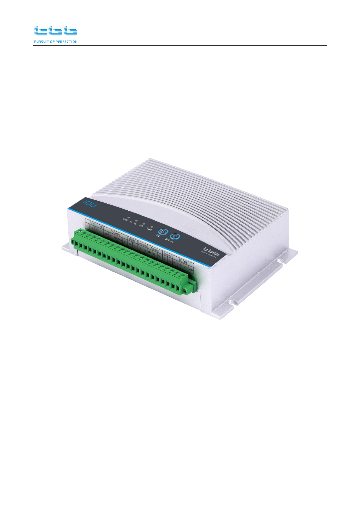
2. Introduction
iDU is a DC UPS integrating multiple functions into one unit, including a smart battery charger,
battery monitor and the load management. The built-in professional adaptive charging algorithm
with automatic temperature charging makes it suitable for composing a power backup system for
various outdoor equipments, such as DAS, RF and FTU etc.
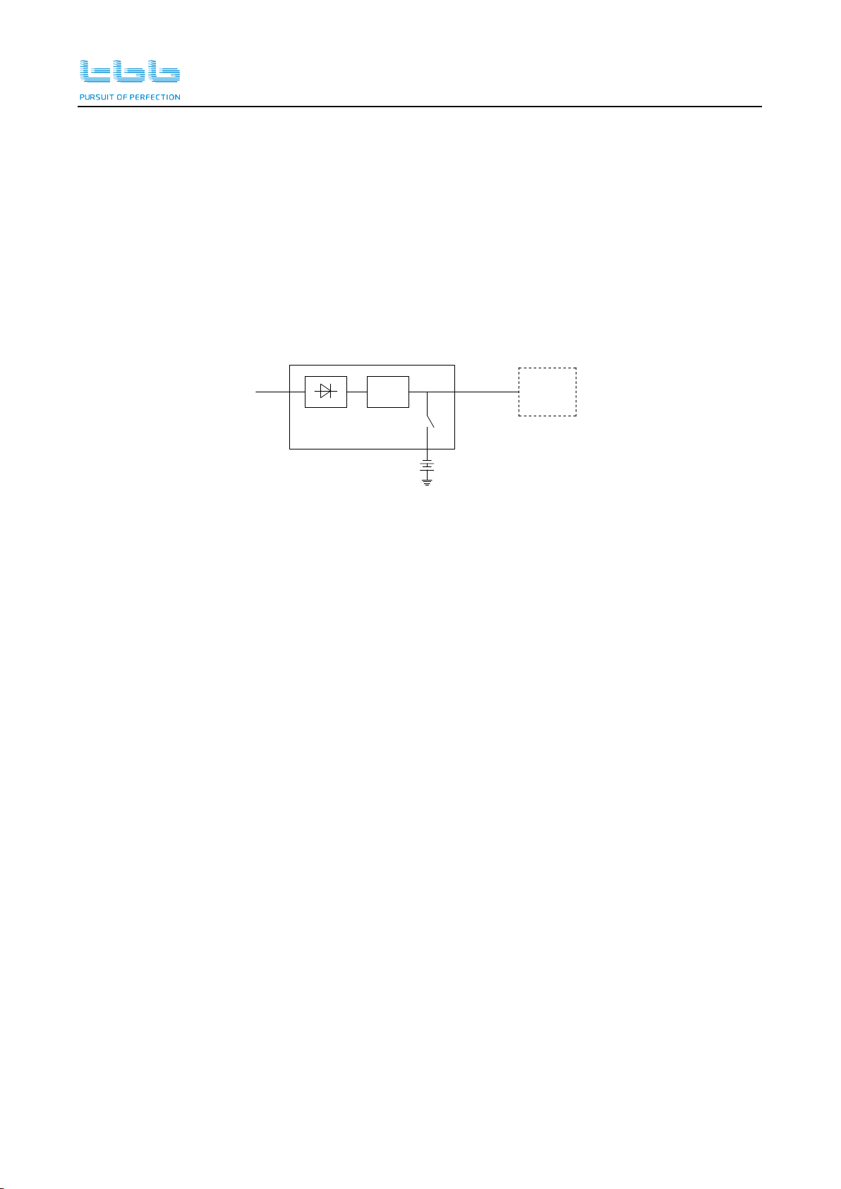
2.1 Schematic Diagram
DC/DC
AC_IN Vo DTU/FTU
When AC grid is available, iDU offers 3 steps smart charging to the battery. At the same time,
it offers the power supply to the load.
When AC grid is not available, battery offers the energy to the loads. iDU alarms via dry
contact.
When battery discharged until the low voltage protection level, iDU cut off the output of
battery and alarms via dry contact.
When the battery in the floating state for a long time, in order to avoid plate passivation, the
module will automatically periodically activation process, at the same time also provide
remote manual activation interface and local activation key, convenient for the user to control
the active state.
Features:
Power factor correction.
Professional temperature compensated battery charging control.
Working temperature: -40℃-70℃.
Low power consumption.
Self- cooling design.
IP55 design.
System data monitor via RS484 communication.
Real-time power supply data.
Real-time alarm data.
Real-time battery data, including battery voltage and discharging current.
iDU series User Manual
TBB Power Co.,Ltd 3
Complete protection.
Over voltage.
Over current.
Over temperature.
Short circuit.
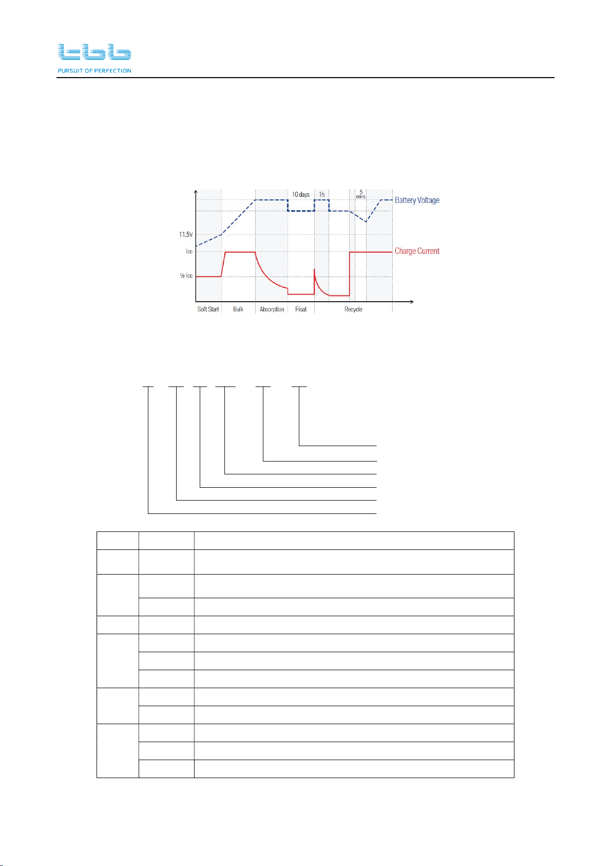
2.2 Charging Curve
2.3 Mode Name
i D DU 120 - 24 - SC
Peak power
Output voltage
Battery type
Product series
1 2 3 4 5 6
Output type
Communication function
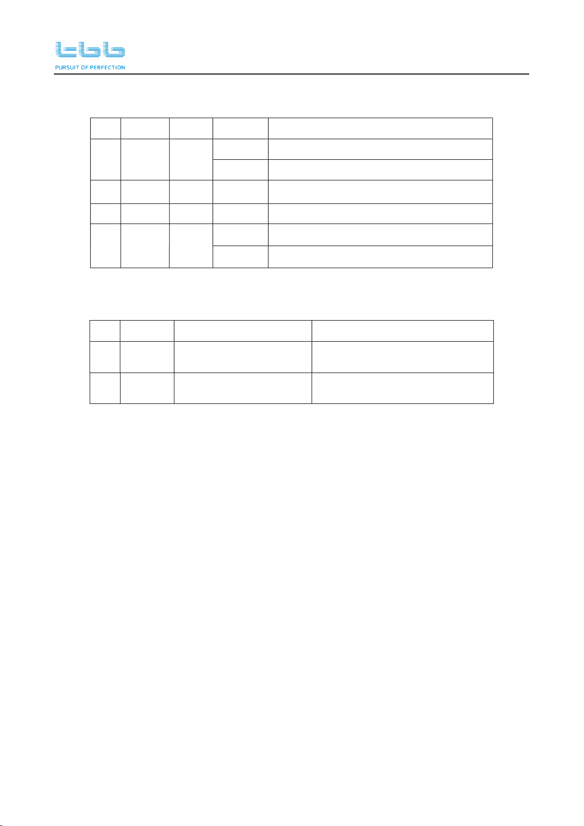
No. Value Description
1 i “i” means with RS484 communication.
2 N/A One output
D Two outputs
3 DU Product series
4
120 Peak power 120W
300 Peak power 300W
500 Peak power 500W
5 24 Output voltage: 24V
48 Output voltage:48V
6
N/A For lead acid battery
SC For super capacitor
LPE For Lithium battery
iDU series User Manual
TBB Power Co.,Ltd 4
3
3.
.
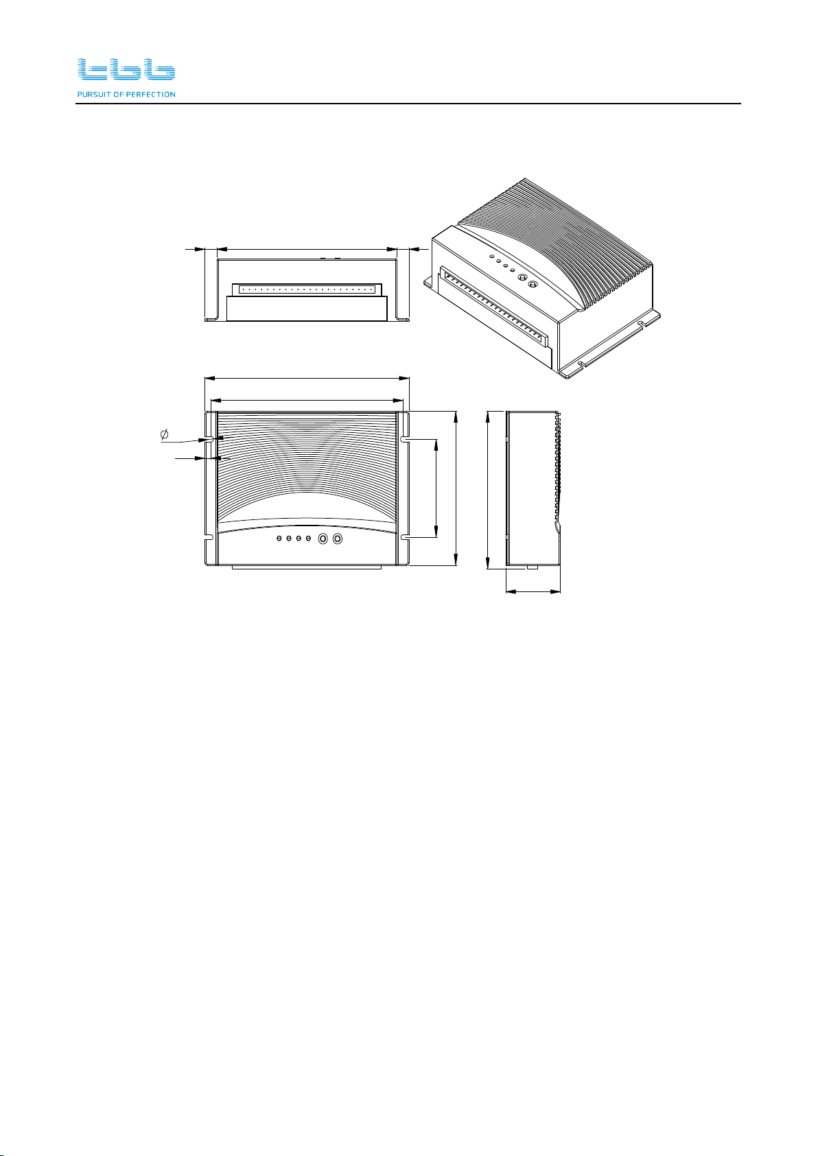
Structure
168
110
70
158
45
112,5
10 148 10
45

iDU series User Manual
TBB Power Co.,Ltd 5
4. O
Op
pe
er
ra
at
ti
io
on
n
4.1 Wiring diagram
4.2 Port definitions
No.
Label
Description No. Label Description
1 L Live line of AC input 12 T1
Temperature sensor port
2 PE Earth line of AC input 13 T2
3 N Neutral line of AC input 14 HK
Battery equilization
interface
4 NC Reserved 15 HG
5 HOK
Dry contacts
16 VG
6 VL 17 B- Battery-
7 VH 18 B+ Battery +
8 POK 19 VO-
DC outputs
9 VC 20 VO-
10 A
RS485 port
21 VO+
11 B 22 VO+
5
T1 T2
6 7 8 9 10 11 12 13 14 15 16 17 18 19 20 214321 22
NC HOK VL VH POK VC A B HK HG VG B- B+ VO- VO+ VO+
VO-
Load
Battery
K2 K3
Temperature
sensor port
Signal output
23 24 25 26
CHG DCHG EQ Fault
27 28
ON
EQ Battery
OFF
ON
OFF
N
AC_N
PE L
Fuse
AC_L
Communication port
iDU series User Manual
TBB Power Co.,Ltd 6
4.3 Buttons and LED indicator
No.
Label Color
Status Description
23 CHG Green
ON Fully charge or ac power supply separately
Flashing
Charging
24 DCHG
Green
ON Discharged
25 EQ Yellow
ON Equilization
26 Fault Red
ON Fault
Flashing
Battery low voltage、Reverse、Over temp
No.
Label Operation Description
27 EQ Long press the button
more than one second Start/End Equalization
28 Battery Long press the button
more than one second Open/Close battery connection

iDU series User Manual
TBB Power Co.,Ltd 7
5
5.
.
S
Sp
pe
ec
ci
if
fi
ic
ca
at
ti
io
on
n
Model iDU500-24 iDU500-48
Output voltage (V) 28.8 57.6
Output
current(A)
Nominal current 3.5 2
Peak current(15S)
20 10
Nominal Input Voltage 165-265VAC,50/60HZ
Charging curve 3 steps smart charging
Temperature compensation Automatic temperature compensation
Absorption voltage(V) 28.8 57.6
Floating voltage(V) 27 54
Charging current (A) 1.5 1
Equilization Automatic/Manual
Efficiency 90%
Ripple noise ≤500mVp-p
Voltage precision ≤2%
Cooling no fans
Working temperature -40℃~ +70℃: full load at 60℃ and derating 60% at 70℃
Communication RS485
Dry contact AC grid fault, Battery low voltage, unit fault and Battery
equilization
Battery low voltage protection
VDC
22 44
Battery EQ voltage protection
VDC
23 46
Protection
Output short circuit Unit cut down the outputs,restart automatically when the
issue disappears
Battery connection reverse
polarity
No output
Charger over temperature Derate the output
Battery over temperature Stop charging
Certification
LVD EN60335-1,EN60335-2-29
EMC EN55014-1,EN55014-2,EN61000-3-2,EN61000-3-3
Structure
Outcase Aluminum
Dimension 168x110x45
168x110x45
168x110x45 1kgs
1kgs
IP protection IP55
Mounting Wall mount
Isulation safety
Isulation resistance ≥50M
Dimension 2.5KV/1min/5mA

iDU series User Manual
TBB Power Co.,Ltd 8
TBB Power Co., Ltd
Web: www.tbbpower.com
Tel: +86-592-5212299
Fax: +86-592-5796070
Email: service@tbbpower.com
This manual suits for next models
2
Table of contents
Other TBB Power Supply manuals


