EKSMA OPTICS PS-80 User manual

HIGH VOLTAGE POWER
SUPPLIES
PS-80
PS-80C
Technical Description
Rev. 2202
2022
Lithuania


i
www.eksmaoptics.com
CONTENTS
CHAPTER 1 WARRANTY ..................................................................................................................... 1
1.1. WARRANTY STATEMENT ....................................................................................................................... 1
1.2. SERVICE CONTACT INFORMATION ............................................................................................................ 1
CHAPTER 2 SPECIFICATIONS............................................................................................................... 2
2.1. GENERAL INFORMATION ....................................................................................................................... 2
2.1.1. Models .................................................................................................................................... 2
2.1.2. Main Components ................................................................................................................... 2
2.2. TECHNICAL SPECIFICATIONS ................................................................................................................... 3
CHAPTER 3 DEVICE LAYOUT ............................................................................................................... 4
CHAPTER 4 SAFETY ............................................................................................................................ 6
CHAPTER 5 QUICK START GUIDE ........................................................................................................ 7
5.1. INSTALLATION OF PS-80 ....................................................................................................................... 7
5.1.1. Ground the HV Power Supply ................................................................................................... 7
5.1.2. Connect DC Power Supply ........................................................................................................ 7
5.1.3. Set HV Voltage ........................................................................................................................ 7
5.1.4. Connect the Load..................................................................................................................... 7
5.2. INSTALLATION OF PS-80C ..................................................................................................................... 8
5.2.1. Ground the HV Power Supply ................................................................................................... 8
5.2.2. Connect CAN Cable .................................................................................................................. 8
5.2.3. Connect DC Power Supply ........................................................................................................ 8
5.2.4. Set HV Voltage ........................................................................................................................ 8
5.2.5. Connect the Load..................................................................................................................... 9

ii
www.eksmaoptics.com
LIST OF FIGURES
FIGURE 1. OUTLINE DRAWING AND DIMENSIONS OF THE HV POWER SUPPLY ................................................................ 4
FIGURE 2. TOP VIEW OF THE HV POWER SUPPLY WITH POTENTIOMETER CONTROL ......................................................... 4
FIGURE 3. TOP VIEW OF THE HV POWER SUPPLY WITH CAN INTERFACE CONTROL (-C MODELS) ........................................ 5
FIGURE 4. CAN-USB CONVERTER ..................................................................................................................... 8
FIGURE 5. CONTROL PANEL APPLICATION ............................................................................................................. 9
LIST OF TABLES
TABLE 1. MODELS ......................................................................................................................................... 2
TABLE 2. MAIN COMPONENTS .......................................................................................................................... 2
TABLE 3. TECHNICAL SPECIFICATIONS.................................................................................................................. 3
TABLE 4. CONTROLS AND CONNECTIONS OF THE HV POWER SUPPLY ........................................................................... 5

1
www.eksmaoptics.com
Chapter 1
WARRANTY
The HV power supplies are protected by a one-year warranty covering labor and parts. The
warranty enters into validity since the shipment date. Any evidence of improper use or
unauthorized repair attempts voids the warranty.
For service/warranty requests, please contact:
EKSMA OPTICS, UAB
c/o EKSMA Optics, UAB
Dvarcioniu st. 2B
LT-10233 Vilnius, Lithuania
Phone:
Fax.:
E-mail:
Website:
+370 5 272 99 00
+370 5 272 92 99
info@eksmaoptics.com
www.eksmaoptics.com

2
www.eksmaoptics.com
Chapter 2
SPECIFICATIONS
The table below lists standard options. Custom voltage modifications may be delivered on
request.
Table 1. Models
Catalog number
HV output
tuning range, kV
Maximal HV current,
mA
Output voltage
control
PS-80-1.8
+0.8 … +1.8
44
By potentiometer
PS-80C-1.8
+0.7 … +1.8
44
By CAN interface
PS-80-2.6
+1.6 … +2.6
30
By potentiometer
PS-80C-2.6
+1.0 … +2.6
30
By CAN interface
PS-80-3.1
+2.1 … +3.1
25
By potentiometer
PS-80C-3.1
+1.3 … +3.1
25
By CAN interface
PS-80-3.6
+2.6 … +3.6
22
By potentiometer
PS-80C-3.6
+1.4 … +3.6
22
By CAN interface
PS-80-4.0
+3.0 … +4.0
20
By potentiometer
PS-80C-4.0
+1.6 … +4.0
20
By CAN interface
Table 2. Main components
Component
Quantity
Notes
High voltage (HV) power supply
1
-
DC power cable (l=1.5m)
1
-
Technical description
1
-
3
www.eksmaoptics.com
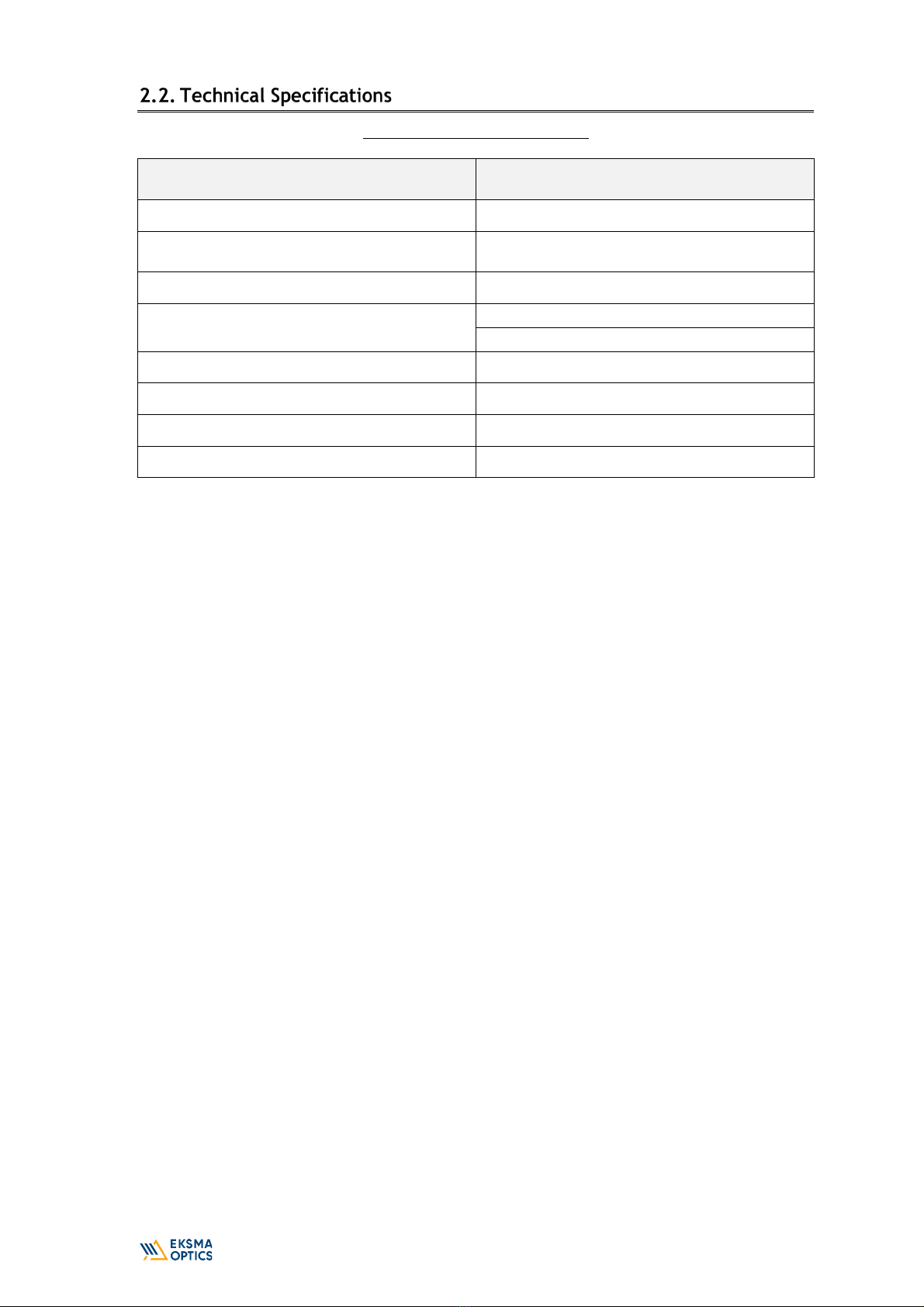
Table 3. Technical specifications
Parameter
Value(s)
Output voltage polarity
Positive
Maximum HV output power at maximal output
voltage, W
80
Output voltage ripple, %
<0.5
Output voltage control
Internal potentiometer
CAN interface (-C models)
Low voltage DC requirements
23.5…25 V, 4200 mA
Maximum ambient temperature for operation, °C
45
Dimensions, mm
175×70×45
Weight, g
265
4
www.eksmaoptics.com
Chapter 3
DEVICE LAYOUT
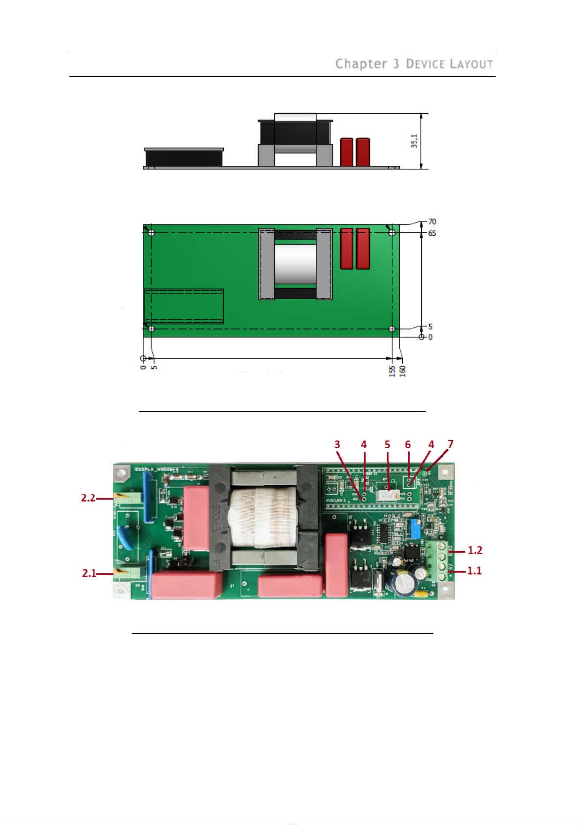
Figure 1. Outline drawing and dimensions of the HV power supply
Figure 2. Top view of the HV power supply with potentiometer control

5
www.eksmaoptics.com
Figure 3. Top view of the HV power supply with CAN interface control (-C models)
Table 4. Controls and connections of the HV power supply
#
Port
1.1
+24V DC supply input
1.2
GND for DC supply input
2.1
GND for HV output
2.2
+ HV output
3
Pin for HV measurement. 1:1000 output.
4
GND pin
5
HV tuning potentiometer
6
HV output off pin (HV output is off when pin connected to GND)
7
LED “+24V” or “No errors” on -C models
8
CAN terminator jumper
9
CAN connector

6
www.eksmaoptics.com
Chapter 4
SAFETY
Equipment is designed to be safe under normal environmental conditions according to 1.4.1.
61010-1@IEC:2010 (Safety requirements for electrical equipment, control and laboratory use):
1. indoor use;
2. altitude up to 2000 m;
3. temperature 5˚C to 35˚C;
4. maximum relative humidity 80% for temperatures up to 31˚C decreasing linearly to 50%
relative humidity at 35˚C;
5. POLLUTION degree 1: no POLLUTION or only dry, non-conductive POLLUTTION occurs.
Warning:
The safety of the system incorporating HV power supply is the responsibility of
the assembler of the system.
Operating the power supply is allowed to persons acquainted with the operation manual and
having permission to deal with voltages over 1000 V.
Do not remove unit covers while power cable is connected to the mains (if applicable).
WARNING
Direct contact with the exposed inner parts of the system when it is powered
may cause human injuries or death.
Do not operate the unit until it is grounded and the load is connected.
Do not use the unit if any defects have been detected.

7
www.eksmaoptics.com
Chapter 5
QUICK START GUIDE
Provide proper ground connection to the HV module. In order to prevent electrical breakdown,
ensure that the distance between the bottom of HV module and the surface below is more than
6 mm.
Connect the +24V DC power supply to the HV module. The DC power supply must be able to
provide the maximum current as per 2.2 TECHNICAL SPECIFICATIONS.
Turn on +24V DC power supply.
Set the output voltage using the potentiometer (#5 in Figure 2). Ways to control of the output
voltage:
1. Measure the output high voltage directly if your control equipment is capable of
measuring high voltage.
2. Alternatively, measure the voltage between points #3 and #4 in Figure 2. This voltage
converts to output voltage approximately as 1V~1 kV.
Turn off +24V DC power supply.
Connect the HV supply load. Check that the connection cables are firmly attached.
HV output can be turned off when pins #4 and #6 in Figure 3 are interconnected.

8
www.eksmaoptics.com
CAN-USB converter is recommended for operation. It can be ordered from Eksma Optics. It
comes together with software and a set of connection cables.
Figure 4. CAN-USB converter
Provide proper ground connection to the HV module. In order to prevent electrical breakdown,
ensure that the distance between the bottom of HV module and the surface below is more than
6 mm.
Connect CAN cable to connector (#9 in Figure 3) from USB-CAN converter and USB cable
between USB-CAN converter and PC.
Connect the +24V DC power supply to the HV module. The DC power supply must be able to
provide the maximum current as per 2.2 TECHNICAL SPECIFICATIONS.
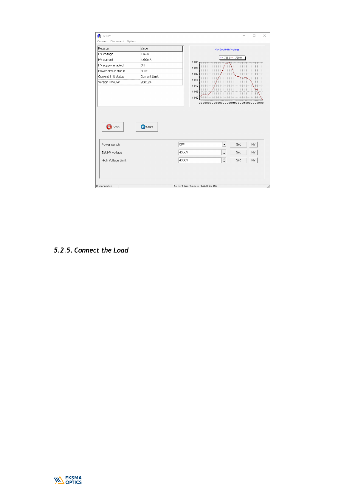
Turn on +24V DC power supply. Use Control panel application to control via PC. It gives
possibility to turn ON/OFF and set high voltage output as well as to read-out actual status.
9
www.eksmaoptics.com
Figure 5. Control panel application
Use CANBrowser software to read-out actual status of HV power supply and save CSV file while
need for technical service or consultation of manufacturer. CSV file includes list of CAN control
registers and actual settings.
Connect the load. Check that the connection cables are firmly attached. Turn on HV supply via
CAN Browser or Control panel application.
This manual suits for next models
1
Table of contents
Other EKSMA OPTICS Power Supply manuals

EKSMA OPTICS
EKSMA OPTICS PS-120 User manual

EKSMA OPTICS
EKSMA OPTICS HVS-100 Parts list manual

EKSMA OPTICS
EKSMA OPTICS HV-170-1.8 User manual

EKSMA OPTICS
EKSMA OPTICS PS-170 User manual

EKSMA OPTICS
EKSMA OPTICS DPB-10-4.2 User manual

EKSMA OPTICS
EKSMA OPTICS PS-40 Parts list manual

EKSMA OPTICS
EKSMA OPTICS HV-200 User manual
Popular Power Supply manuals by other brands

Eaton
Eaton Crouse-hinds series instruction manual

Elektro-Automatik
Elektro-Automatik PSI 9040-20 T operating guide

Fellowes
Fellowes esi FlexCharge4C Assembly instructions

Rockwell Automation
Rockwell Automation 1606-XLE80E manual

Delta Electronics
Delta Electronics Delphi E48SR12007 datasheet

Goobay
Goobay 59029 user manual


