EKSMA OPTICS DPB-10-4.2 User manual

HIGH VOLTAGE
DRIVERS
DPB-10-4.2
DPB-10-4.2-Al
DPB-5-5.5
DPB-5-5.5-Al
Technical Description
Rev. 2201
2022
Lithuania


i
www.eksmaoptics.com
CONTENTS
CHAPTER 1 WARRANTY ..................................................................................................................... 1
1.1. WARRANTY STATEMENT ....................................................................................................................... 1
1.2. SERVICE CONTACT INFORMATION ............................................................................................................ 1
CHAPTER 2 SPECIFICATIONS............................................................................................................... 2
2.1. GENERAL INFORMATION ....................................................................................................................... 2
2.1.1. Models .................................................................................................................................... 2
2.1.2. Main Components ................................................................................................................... 2
2.2. TECHNICAL SPECIFICATIONS ................................................................................................................... 3
CHAPTER 3 DEVICE LAYOUT ............................................................................................................... 4
CHAPTER 4 SAFETY ............................................................................................................................ 7
CHAPTER 5 IMPORTANT NOTES ......................................................................................................... 8
CHAPTER 6 QUICK START GUIDE ...................................................................................................... 10
6.1. SET JUMPER #5 TO REQUIRED OPERATION MODE ....................................................................................... 10
6.2. CONNECT WIRES TO THE POCKELS CELL ................................................................................................... 10
6.3. GROUND THE POCKELS CELL DRIVER TOGETHER WITH THE GENERATOR AND HV SUPPLY ...................................... 10
6.4. SUPPLY VOLTAGE TO THE DRIVER FROM THE DC POWER SUPPLY .................................................................... 11
6.5. SUPPLY VOLTAGE FROM THE HV SUPPLY.................................................................................................. 11
6.6. PROVIDE SYNCHRONIZATION PULSES FROM THE GENERATOR......................................................................... 11

ii
www.eksmaoptics.com
LIST OF FIGURES
FIGURE 1. OUTLINE DRAWING AND DIMENSIONS OF THE DRIVER WITHOUT HV SUPPLY .................................................... 4
FIGURE 2. OUTLINE DRAWING AND DIMENSIONS OF THE DRIVER WITH HV SUPPLY WITHOUT CASE ..................................... 4
FIGURE 3. OUTLINE DRAWING AND DIMENSIONS OF THE DRIVER WITH CASE AND HV SUPPLY (-AL) .................................... 5
FIGURE 4. VIEW OF THE ENCASED DRIVER WITH HV SUPPLY (-AI) .............................................................................. 5
FIGURE 5. VIEW OF THE DRIVER WITHOUT CASE..................................................................................................... 6
FIGURE 6. DRIVER OPERATION CHART ................................................................................................................. 8
FIGURE 7. CONTROL TIMING FOR 1-INPUT (LEFT) AND 2-INPUT (RIGHT) CONTROLLED DRIVER ......................................... 10
FIGURE 8. INPUT CIRCUIT OF DRIVER................................................................................................................. 12
LIST OF TABLES
TABLE 1. MODELS ......................................................................................................................................... 2
TABLE 2. MAIN COMPONENTS .......................................................................................................................... 2
TABLE 3. TECHNICAL SPECIFICATIONS.................................................................................................................. 3
TABLE 4. PORTS SEEN IN TOP VIEW OF THE DRIVER ................................................................................................. 6

1
www.eksmaoptics.com
Chapter 1
WARRANTY
The Pockels cell drivers are protected by a one-year warranty covering labor and parts. The
warranty enters into validity since the shipment date. Any evidence of improper use or
unauthorized repair attempts voids the warranty.
For service/warranty requests, please contact:
EKSMA OPTICS, UAB
c/o EKSMA Optics, UAB
Dvarcioniu st. 2B
LT-10233 Vilnius, Lithuania
Phone:
Fax.:
E-mail:
Website:
+370 5 272 99 00
+370 5 272 92 99
info@eksmaoptics.com
www.eksmaoptics.com

2
www.eksmaoptics.com
Chapter 2
SPECIFICATIONS
Table 1. Models
Model
Description
DPB-10-4.2
10kHz repetition rate, 4.2kV output, open PCB
DPB-10-4.2-Al
10kHz repetition rate, 4.2kV output, with case and HV supply
DPB-5-5.5
5kHz repetition rate, 5.5kV output, open PCB
DPB-5-5.5-Al
5kHz repetition rate, 5.5kV output, with case and HV supply
Table 2. Main components
Component
Quantity
Notes
High voltage (HV) driver DPB-*-*-*
1
-
DC power cable (l=1.5m)
1
-
BNC-SMB cables (l=1.5m)
2
-
HV power supply cable (l=1m)
1
Not supplied if DPB-*-*-* driver and HV
power supply are ordered and screwed
together.
Pair of cables for HV output to the
Pockels cell (<10 cm)
1
-
Technical description
1
-

3
www.eksmaoptics.com
Table 3. Technical specifications
Parameter
Value(s)
DPB-10-4.2(-Al)
DPB-5-5.5(-Al)
Maximum output pulse amplitude (HV), kV
4.2
at 2.2 kV HV supply
5.5
at 2.8 kV HV supply
Minimum output pulse amplitude (HV), kV1
±1.4
Maximum HV consumption (DPB load = 6 pF),
W
5
Polarity output
Bipolar
External triggering input
1 or 2 pulses
Maximum capacity load at maximal repetition
rate and HV supply voltage, pF2
12
6 for – AI models
HV pulse rise/fall time, ns (HV load=6pF)
<6/6
<7/7
HV pulse duration, ns
30…3000
Maximum HV repetition rate, kHz
10
5
HV pulse delay, ns
~30
External triggering pulse amplitude @50W load,
V
2…6
External triggering pulse rise time, ns
<10
External triggering pulse duration for 2-input
control mode, ns
>20
External triggering pulse delay between IN1
and IN2 for 2 input control mode or IN1 pulse
duration in 1- input control mode , ns
30…3000
Low voltage DC requirements
15…25 V, 150 mA
or
12 V, 200 mA
DC Connectors
Molex Micro-Fit 3.0
Dimensions, mm
See figure(s) in CHAPTER 3 DEVICE LAYOUT
140×60×29 (without HV supply)
151×71×52 (with HV supply)
192×81×75 (-Al)
Weight, g
70 (without HV supply)
200 (with HV supply)
480 (-Al)
1
Minimal voltage limit can be switched off, see CHAPTER 5 Specifications .
2
Voltage or repetition rate derating is necessary if capacitance of your Pockels cell is higher. Contact
Eksma Optics for suggestions.
4
www.eksmaoptics.com
Chapter 3
DEVICE LAYOUT
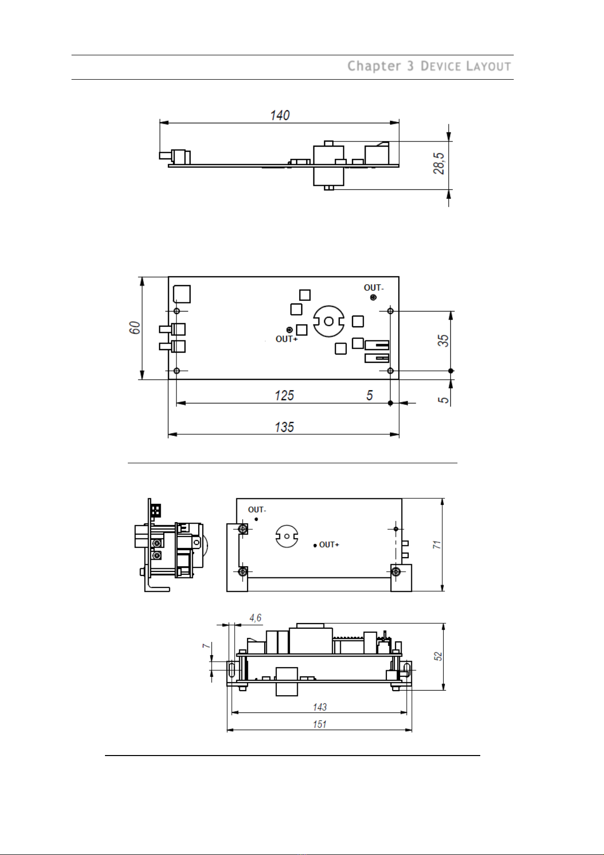
Figure 1. Outline drawing and dimensions of the driver without HV supply
Figure 2. Outline drawing and dimensions of the driver with HV supply without case

5
www.eksmaoptics.com
Figure 3. Outline drawing and dimensions of the driver with case and HV supply (-Al)
Figure 4. View of the encased driver with HV supply (-AI)
6
www.eksmaoptics.com
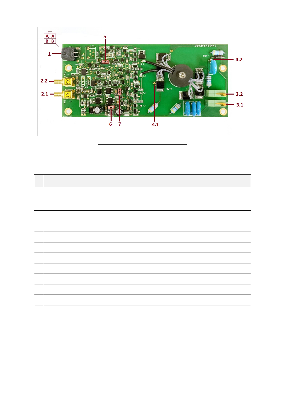
Figure 5. View of the driver without case
Table 4. Ports seen in top view of the driver
#
Port
1
Connector Molex 4 (Microfit series) - interface for +DC (24 VDC) supply (“A” is +DC; “B” is
GND)
2.1
X1(SYNC IN1) for HV opening, or SYNC IN in 1-input control mode
2.2
X2 (SYNC IN2) for HV closing
3.1
Connector for GND input from HV supply
3.2
Connector for +HV input from HV supply
4.1
HV pulse output pin +OUT
4.2
HV pulse output pin -OUT
5
Jumper to toggle SYNC IN mode between one-and-two pulses control
6
Jumper for commutation of DC voltage mode (with jumper- +12V; without jumper- +15…25V)
7
Protection jumper
8
HV power supply tuning port (only for –Al drivers)
9
Grounding screw (only for –Al drivers)

7
www.eksmaoptics.com
Chapter 4
SAFETY
Equipment is designed to be safe under normal environmental conditions according to 1.4.1.
61010-1@IEC:2010 (Safety requirements for electrical equipment, control and laboratory use):
1. indoor use;
2. altitude up to 2000 m;
3. temperature 5ºC to 35˚C;
4. maximum relative humidity 80% for temperatures up to 31ºC decreasing linearly to 50%
relative humidity at 35ºC;
5. POLLUTION degree 1: no POLLUTION or only dry, non-conductive POLLUTTION occurs.
Warning:
The safety of the system incorporating driver and HV power supply is the
responsibility of the assembler of the system.
Operating the driver is allowed to persons acquainted with the operation manual and having
permission to deal with voltages over 1000 V.
Do not remove unit covers while power cable is connected to the mains (if applicable).
Do not touch any parts of the system when high voltage is applied, as it may cause injury or
death.
Do not operate the unit until it is grounded and the load is connected.
Do not use the unit if any defects have been detected.

8
www.eksmaoptics.com
Chapter 5
IMPORTANT NOTES
Please read these important notes before using the product!
1. Different voltages may be supplied to the driver depending on the jumper #6 in Figure 5:
• Without jumper: +15…25V
• With jumper: +12V±0.5V
2. External triggering pulses to inputs X1 (SYNC IN1) and X2 (SYNC IN2) may be applied only
if high voltage and DC power are provided and turned on. When turning off the driver, first
turn off synchronization pulses, then turn off the power. Otherwise the driver may be
damaged.
Incorrect driver operation.
SYNC IN pulses appears before HV and
24V; SYNC IN pulses continues after 24V is
switched off; HV supply gives an overshot.
Correct driver operation
Figure 6. Driver operation chart
The DPB driver has protection against damage due above wrong SYNC IN timing. However,
this protection blocks output if HV supply is set below 0.5Umax. If you still need to operate
below this limit, the protection can be switched off by shortening pins of jumper #7 Figure
5). This case HV supply voltage and following amplitude of output pulses can be reduced
down to 0 V. You should be absolutely sure that correct operation conditions as per Figure
6 are fulfilled.
3. The output pulse is provided between OUT+ and OUT- connectors. Do not connect an
oscilloscope or any other device to the OUT connector. The wire contact with the Pockels
cell must be proper in order to avoid a discharge, which may damage the driver. Do not
connect the driver without a capacitive load (4…10 pF) as this may damage the driver.
4. The pulse shape (including fronts) can be measured indirectly. On your oscilloscope, select
1 V sensitivity and the 1 MW input. Use isolated 1:10 oscilloscope probe for measurement.
Move the probe slowly and carefully toward the hot output wire. When the probe is ~10 mm
away from the hot output wire, the pulse shape should appear in the oscilloscope
(amplitude should be several volts). Do not place the probe too close to the hot output wire
– a discharge may start and damage the driver. This measurement method is not suitable for
measuring >500 ns pulses.

9
www.eksmaoptics.com
5. Do not attempt to measure the parameters of any parts of the driver’s electronics using
an oscilloscope, especially when the driver is running in pulsed mode. Attempts to measure
parameters of certain parts of the driver’s circuitry may lead to damage.
10
www.eksmaoptics.com
Chapter 6
QUICK START GUIDE
This step describes the commutation jumper marked “#5”in Figure 5 / Table 4
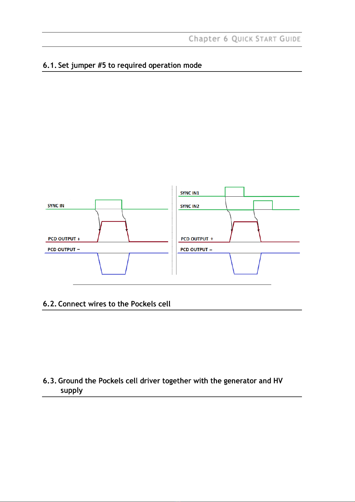
The DPB series driver may be controlled by one or two SYNC IN signals (see Figure 7), depending
on the jumper position:
• Jumper position 1: 1-input control mode
SYNC IN1 rising edge turns HV to Pockels cell on, falling edge turns the voltage off.
• Jumper position 2: 2-input control mode
SYNC IN1 rising edge turns voltage on, SYNC IN2 rising edge turns the voltage off.
Either of the two jumper positions must be selected when operating the driver. Do not leave the
driver with no position set on the jumper.
Cables from generator must be of equal length for control by two synchronization pulses.
Figure 7. Control timing for 1-input (left) and 2-input (right) controlled driver
The wires leading from outputs OUT1 and OUT2 to the Pockels cell must be about 0.24 mm2 CSA.
Both the wires must be as short as possible and equal length. The length of each wire must be
not exceeding 100 mm. They should be located at least 5 mm away from any conductive
material (including the operator’s fingers and instruments) – this is done to avoid any additional
capacitive load. Otherwise, driver characteristics may degrade and/or the driver may get
damaged.
The driver output of several kilovolts (kV) with very fast edges is a powerful source of
electromagnetic interference (EMI). Please ensure proper wiring and grounding to avoid
problems caused by interference.
The best solution to minimize EMI is to mount the driver and the HV power supply on the metal
body of the laser. The driver base plate must have very good contact with the ground wire of the
HV power supply, such as the four mounting holes on the edges of the board. This is enough in

11
www.eksmaoptics.com
most cases, provided the driver is firmly attached to the metal laser body and the HV power
supply is attached to the same body via all available mounting holes.
If the EMI level is still very high, attempt mounting ferrites on all power and control wires
leading to the driver and power supply (except wires to the Pockels cell).
Please note that the aluminum case of the driver is not designed to provide effective EMI
shielding. Essentially, correct wiring provides best results.
For a safe start of the driver, the DC power supply must provide at least 0.6 A peak current when
turning on. Although most DC power supplies are capable of providing this, it is recommended
to double-check your supply as an insufficient peak current may damage the driver.
Set output voltage from HV supply.
If the HV power supply is manufactured by a third party, before supplying voltage, ensure there
is no overvoltage while turning it on.
If driver is fixed together with HV power supply, connect CAN cable to HV tuning port #8 in
Figure 4 or set HV voltage by potentiometer.
It is necessary to measure the generator output voltage with a 50W load before applying
synchronization signals to the DPB driver. The signal voltage must be at 2…6 V level. Make sure
that the duration of SYNC IN1 pulse is longer than 30 ns in single-pulse driving, or delay between
SYNC IN1 and SYNC IN2 is greater than 30 ns in two-pulse driving. A shorter duration or delay of
the synchronization pulses may damage the driver.
After the generator output voltage is measured, remove the 50W load and provide
synchronization pulses to the driver.
Note that the output pulse duration and delay depend of the control pulse signal level and HV
pulse rise/fall time (edges of HV pulse); the duration may vary in the order of several
nanoseconds (in positive and negative directions). It is not recommended to use control signals
with edges longer than 10 ns. Figure 8 presents the input circuit. Below 30 ns, driver output
voltage starts decreasing. Output pulses shorter than 30 ns can damage the driver.
Note:
After +DC voltage is applied, the first synchronization pulse is skipped.

12
www.eksmaoptics.com
Figure 8. Input circuit of driver
This manual suits for next models
3
Table of contents
Other EKSMA OPTICS Power Supply manuals

EKSMA OPTICS
EKSMA OPTICS HV-200 User manual

EKSMA OPTICS
EKSMA OPTICS HV-170-1.8 User manual

EKSMA OPTICS
EKSMA OPTICS HVS-100 Parts list manual

EKSMA OPTICS
EKSMA OPTICS PS-170 User manual

EKSMA OPTICS
EKSMA OPTICS PS-80 User manual

EKSMA OPTICS
EKSMA OPTICS PS-40 Parts list manual

EKSMA OPTICS
EKSMA OPTICS PS-120 User manual


