- 6 -
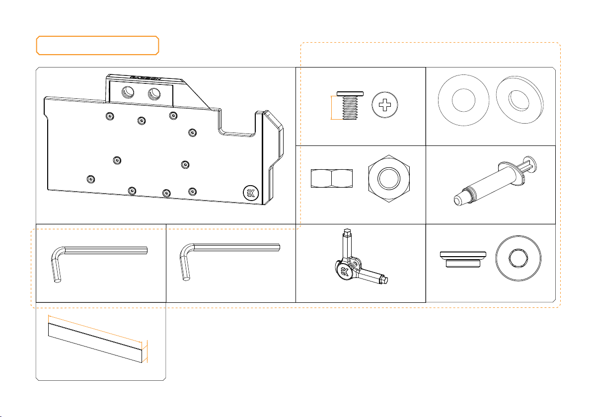
TECHNICAL SPECIFICATIONS AND WATER BLOCK PARTS
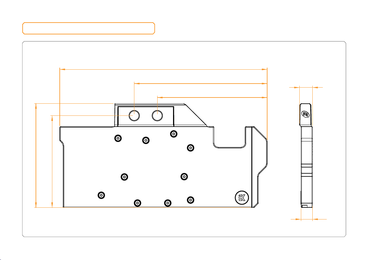
Technical Specification:
- Dimensions: (L x H x W) – 260.5 x 130.5 x 16.5 mm
- D-RGB cable length: 500 mm
- D-RGB LED count: 8
- D-RGB connector standard 3-pin (+5V, Data, Blocked, Ground)
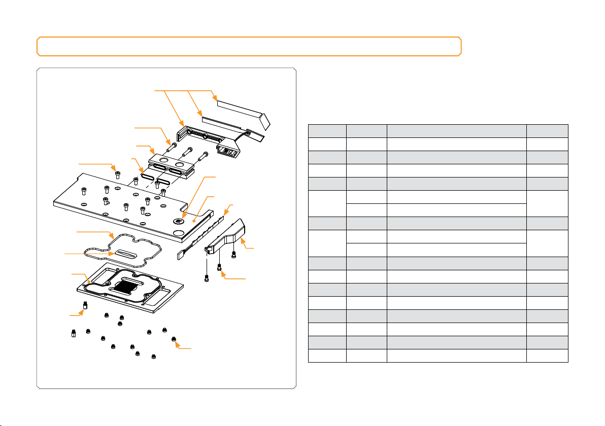
Position EAN Description Quantity
1103431 Terminal cover + D-RGB LED 1
28311 M4 x 20 DIN7984 Screw 3
3101628 FC Terminal 1
45155 FC Terminal O-ring 15 x 1 mm 2
5103725 Top Plate (Plexi) 1
103726 Top Plate (Acetal)
6101290 LED D-RGB Strip 1
7103728 Stickout (Black) 1
103730 Stickout (White)
8100753 Stickout standoff 3
98533 Standoff M4/M2.5 x 2.5 12
10 8541 Standoff M4/M2.5 x 6.6 2
11 103724 Coldplate (Nickel) 1
12 103731 Main O-Ring 1
13 104210 Jet plate 1
14 100663 EK - Badge 1
15 9013 M4 x 8 DIN7984 Screw 10
13
6
5
7
9
8
1
4
2
3
11
15
12
10
14