EL GENS LPC-P150S-2VETx User manual

1
LPC P-cap Panel PC 2VET Series
With Gen 11 Core-i7/i5
User Manual
Published in Taiwan
Release Date : Oct 2021
Revision : V0.1

2
Warning!
This equipment generates, uses and can radiate radio frequency energy and if not installed
and used in accordance with the instructions manual, it may cause interference to radio
communications. It has been tested and found to comply with the limits for a Class A
computing device pursuant to FCC Rules, which are designed to provide reasonable protection
against such interference when operated in a commercial environment. Operation of this
equipment in a residential area is likely to cause interference in which case the user at his own
expense will be required to take whatever measures may be required to correct the
interference.
Electric Shock Hazard –Do not operate the machine with its back cover removed. There are
dangerous high voltages inside.
Disclaimer
This information in this document is subject to change without notice. In no event shall ELGENS
Co., Ltd. be liable for damages of any kind, whether incidental or consequential, arising from either
the use or misuse of information in this document or in any related materials.
Packing List ®
Accessories (as ticked) included in this package are:
□Panel Mounting Kits
□3 Pin Male Terminal Block
□Optional Adapter
□Other.___________________(please specify)
Safety Precautions
Follow the messages below to avoid your systems from damage:
◆Avoid your system from static electricity on all occasions.
◆Prevent electric shock. Don‘t touch any components of this card when the card is power-
on. Always disconnect power when the system is not in use.
◆Disconnect power when you change any hardware devices. For instance, when you
connect a jumper or install any cards, a surge of power may damage the electronic
components or the whole system.

3
Table of Contents
CHAPTER 1 GETTING STARTED .....................................................................................................4
1.1 BRIEF DESCRIPTION OF LPC P-CAP 2VET SERIES.............................................................................4
1.2 SYSTEM SPECIFICATIONS ...........................................................................................................5
1.3 DIMENSION ...........................................................................................................................7
1.4 GENERAL REAR IO PLACEMENT ................................................................................................11
1.5 FRONT VIEW OF LPC-2VETX SERIES..........................................................................................12
1.6 REAR VIEW OF LPC-2VETX SERIES ...........................................................................................12
1.7 TOP /BOTTOM IO VIEW ........................................................................................................13
CHAPTER 2 SYSTEM SETUP .......................................................................................................14
2.1 INSTALLING OF DDR4 SO-DIMM ............................................................................................14
2.2 INSTALLING OF M.2...............................................................................................................15
2.3 INSTALLING OF HDD..............................................................................................................15
CHAPTER 3 BIOS SETUP............................................................................................................16
3.1 ENTERING SETUP...................................................................................................................16
3.2 MAIN MENU .......................................................................................................................17
3.3 ADVANCED FUNCTION............................................................................................................18
3.4 CHIPSET..............................................................................................................................30
3.5 SECURITY ............................................................................................................................37
3.6 BOOT.................................................................................................................................39
3.7 SAVE &EXIT........................................................................................................................40
APPENDIX A : GPIO GUIDE..................................................................................................41
APPENDIX B : Software Functions.........................................................................................44
APPENDIX C : RAID Functions ...............................................................................................47

4
Chapter 1 Getting Started
1.1 Brief Description of LPC P-cap 2VET Series
The LPC P-cap 2VET series is a power-optimized and delivers robust performance-per-watt for
embedded HMI, powered by Intel® Gen 11 CoreTM i7/i5 UP3-Series (Tiger Lake UP3) processors.
It comes with a Bezel-Free design, up to 32GB DDR4 memory, M.2 slot and a SATA 2.5-inch
lockable HDD tray, audio jack, 2 RJ45 Ethernet, DC input, and 4 USB ports. The unit supports
Windows 10.
The Elgens fanless touch panel computer is ideal for use as Web Browser, Terminal and HMI at
all levels of automation control.

5
1.2 System Specifications
Model
Number
LPC-P150S-2VETx
LPC-P156W-
2VETx
LPC-P185W-
2VETx
LPC-P190S-2VETx
Max
Resolution
1024*768
1920*1080
1920*1080
1280*1024
Color
16.7M
16.2M
16.2M
16.7M
Luminance
300 nits
450 nits
350 nits
350 nits
View Angle
176/176
170/170
178/178
170/160
Contrast Ratio
2500
800
1000
1000
Computing
Processor
Intel® TGL UP3 Core i7-1185G7E/i5-1145G7E Processor
System
Memory
1 DDR4-3200 SO-DIMM, up to 32GB
Storage
1 x SATA 6Gb/s ports (1 x lockable HDD tray)
1 M.2 Key B 2260 Socket
External I/O
Port
2 x DisplayPort Connector
4 x USB Connector
2 x RJ45 LAN
4 x COM RS-232/422/485 DB9 Connector
1 x Audio
1 x Power press button
1 x 3-Pin Power Input
Expansion
Slots
1 x M.2 Key E Socket (2230)
OS support
Windows 10, Linux (by Request)
Touch Screen
Type
USB P-cap Touch
Light
Transmission
90%
Power Supply
Power Input
■DC9~55V Wide Range Power Input
■Input on board fuse
■Input reverse protection
Mechanical
Construction
Metal case with Aluminum Bezel and Heatsink
IP Rating
Front Panel compliant IP65
Mounting
Panel/VESA
Environmental
Operating/Stor
age
Temperature
-40~70 °C
Storage
Humidity
10~90% @40 °C non-condensing

6
Order Information
LPC-Pxxxx-
2VET7
Bezel-Free P-cap Panel PC with i7-1185G7,DC 9~55V Power Input, including a
3-Pin Power Adapter
LPC-Pxxxx-
2VET5
Bezel-Free P-cap Panel PC with i5- 1145G7E, DC 9~55V Power Input, including
a 3-Pin Power Adapter
Order Code
LPC-PxxxS/W
-H / -OB / -G / -AG / -AR / -B / -V / -T
xxx = size, For example, 10.1” = 101
S = Dimension Ratio Square = 4:3 or 5:4
W= Dimension Ration Wide = 16:9 or 16:10
H = High Brightness 1000 nits LED backlight (Optional to 1600 nits backlight)
OB = Optical Bonding
G = Glass without touch
AG = Anti-Glare
AR = Anti-Reflection
V = Vandal Proof Glass
T = Backside Heatsink for Operating Temperature 60°C
Contact Elgens Sales for detail information

7
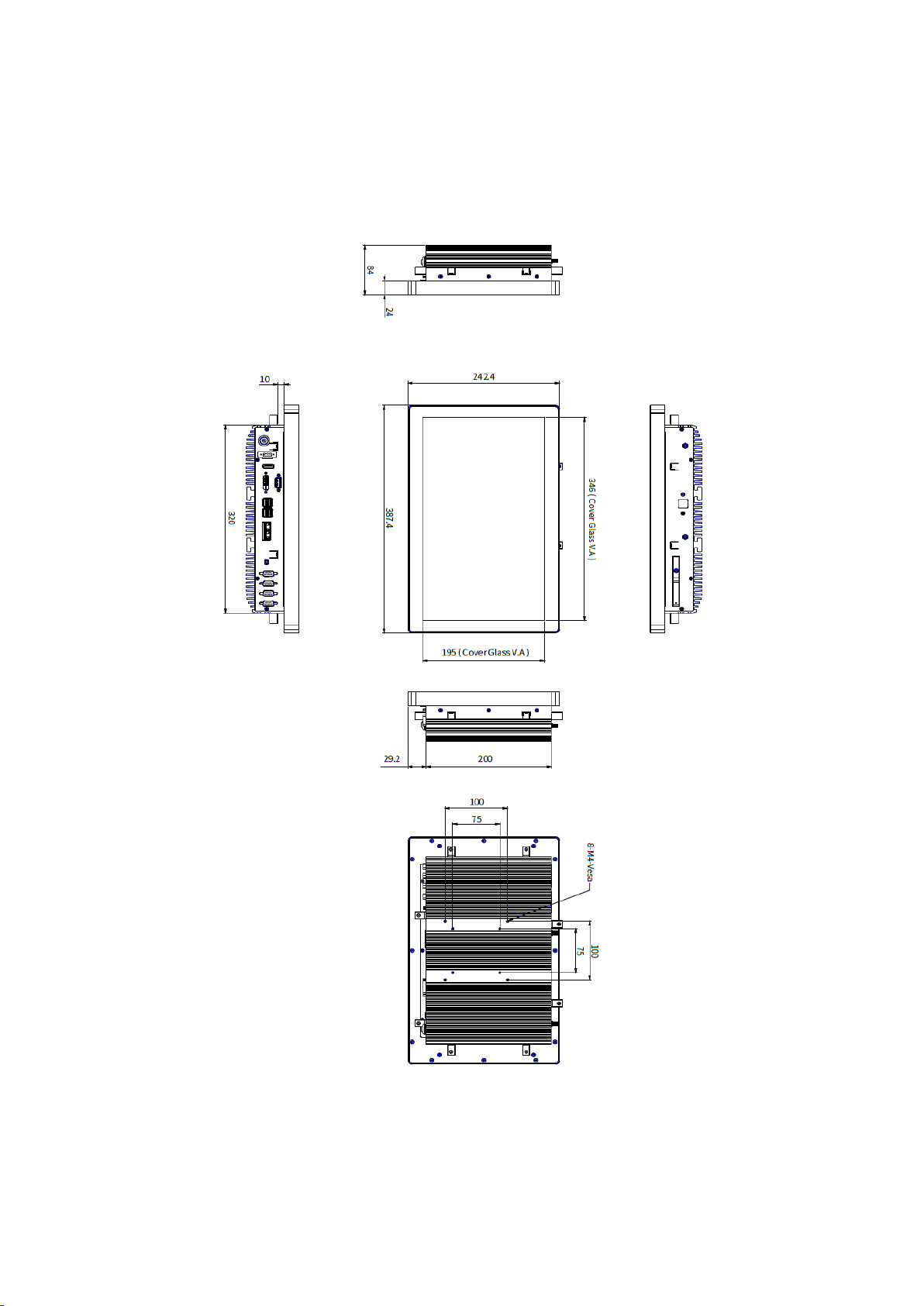
1.3 Dimension
1.3.1 LPC-P150S-2VETx Drawing
8
1.3.2 LPC-P156W-2VETx Drawing

9
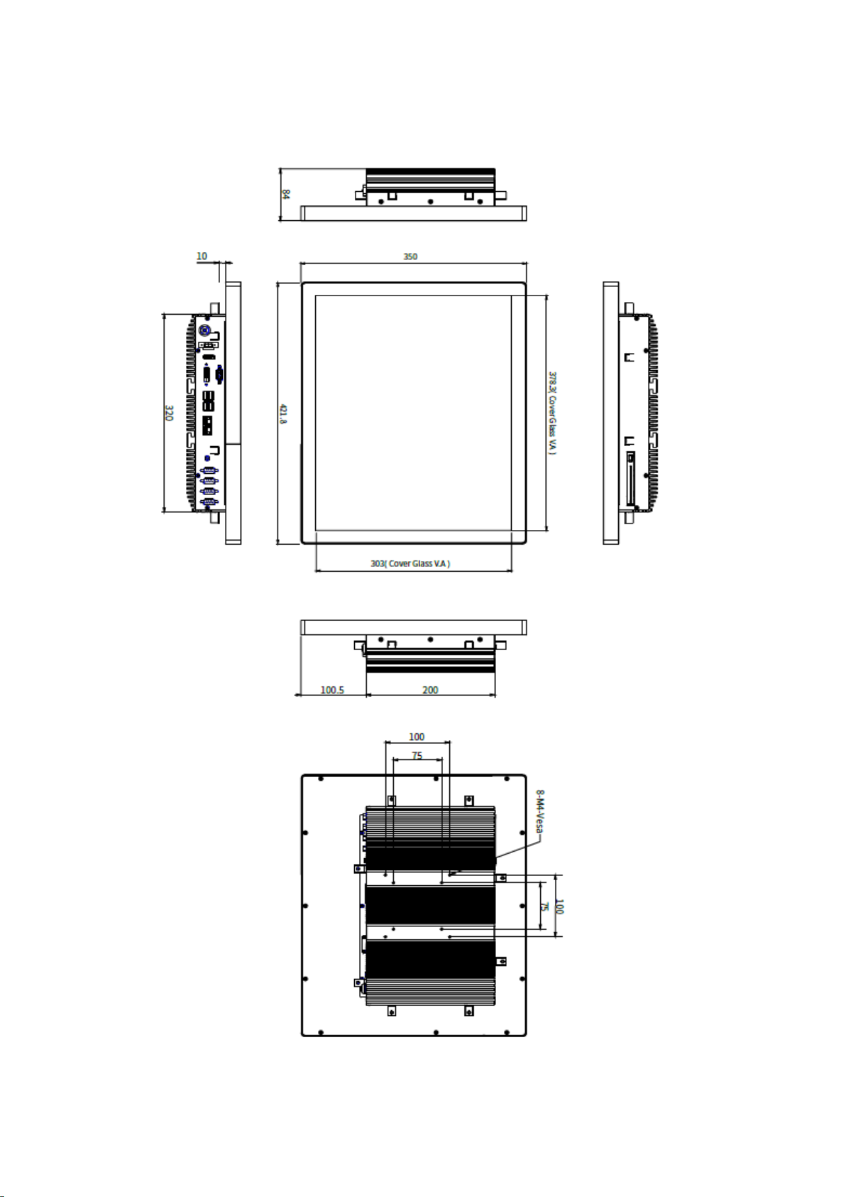
1.3.3 LPC-P185W-2VETx Drawing
10
1.3.4 LPC-P190S-2VETx Drawing

11
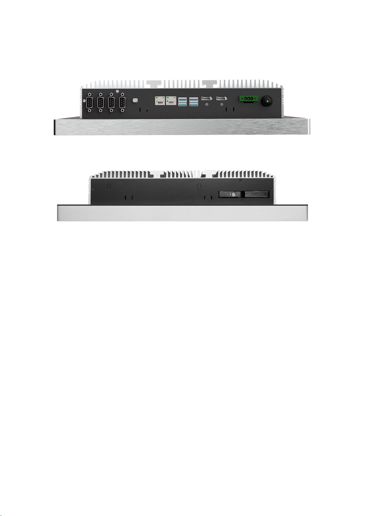
1.4 General Rear IO Placement
COM 1~4 is RS-232 as default and can be adjustable to RS-422/485 by BIOS.
Power input terminal block pin definition is as below.
12
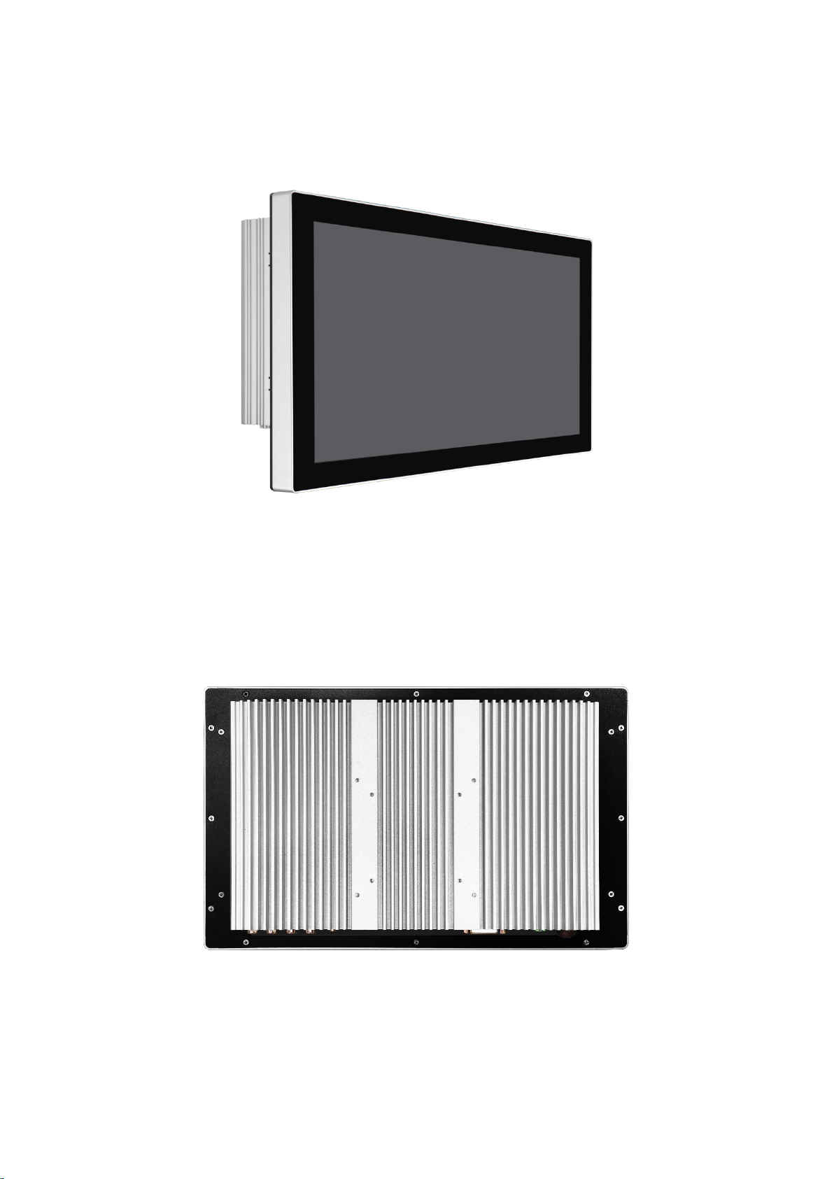
1.5 Front View of LPC-2VETx Series
1.6 Rear View of LPC-2VETx Series
13
1.7 Top / Bottom IO View

14
Chapter 2 System Setup
2.1 Installing of DDR4 SO-DIMM
Step 1 Install DDR4 RAM module into SO-DIMM slot.
Step 2 Make sure the RAM module is locked by the memory slot.

15
2.2 Installing of M.2
Step 1 Install M.2 into the M.2 slot.
Step 2 Fasten one PH-M3x4L screw.
2.3 Installing of HDD

16
Chapter 3 BIOS Setup
3.1 Entering Setup
BIOS provides an interface for users to check and change system configuration. The BIOS
setup program is accessed by pressing the <Del> key when POST display output is shown.
Figure 2-1 : Entering Setup Screen

17
3.2 Main Menu
The main menu displays BIOS version and system information. There are two options on
Main menu.
Figure 2-2 : BIOS Main Menu
System Date
Set the Date. Use Tab to switch between Date elements.
System Time
Set the Time. Use Tab to switch between Time elements.

18
3.3 Advanced Function
Select Advanced tab to enter advanced BIOS Setup options such as CPU configuration
SATA configuration, and USB configuration.
Figure 4-3 : BIOS Advanced Menu

19
3.3.1 CPU Configuration
Figure 2-3-1 : CPU Configurations
CPU Flex Ratio Override
Enable/Disable CPU Flex Ratio Programming.
Hardware Prefetcher
To turn on/off the MLC streamer prefetcher.
Adjacent Cache Line Prefetch
To turn on/off prefetching of adjacent cache lines.
Intel (VMX) Virtualization Technology
When enabled, a VMM can utilize the additional hardware capabilities provided
by Vanderpool Technology.
Active Processor Cores
Number of cores to enable in each processor package.
Hyper-threading
Enabled or Disabled Hyper-Threading Technology.
AES
Enable/disable AES (Advanced Encryption Standard).
Intel Trusted Execution Technology
Enables utilization of additional hardware capabilities provided by Intel Trusted
Execution Technology.
Changed require a full power cycle to take effect.
Total Memory Encryption
Configure Total Memory Encryption (TME) to protect DRAM data from physical
attacks. Either the IBECC or the TME can be enabled.

20
3.3.2 Power & Performance
Figure 2-3-2 : Power & Performance
3.3.2.1 CPU - Power Management Control
Figure 2-3-3 : CPU - Power Management Control
Boot performance mode
Select the performance state that the BIOS will set starting from reset vector.
Intel® SpeedStep™
Allows more than two frequency ranges to be supported.
Race To Halt (RTH)
Enable/Disable Race To Halt feature. RTH will dynamically increase CPU
frequency in order to enter pkg C-State faster to reduce overall power. (RTH is
controlled through MSR 1FC bit 20).
Intel® Speed shift Technology
Enable/Disable Intel® Speed Shift Technology support. Enabling will expose the
CPPCv2 interface to allow for hardware controlled P-states.
Turbo Mode
Enable/Disable processor Turbo Mode (requires Intel Speed Step or Intel Speed
Shift to be available and enabled).
Config TDP Configurations
Config TDP Configurations.
C states
Enable or disable CPU Power Management. Allows CPU to go to C states when
it's no 100% utilized.
Enhanced C-states
Enable/disable C1E. When enabled, CPU will switch to minimum speed when
all cores enter C-State.
This manual suits for next models
3
Table of contents


