ELAD FDM-DUO User manual

www.eladit.com
ELAD FDM-DUO
Dual Mode SDR Transceiver
USER MANUAL

ELAD FDM-DUO User Manual - Rev. 2.3 - 06/2016
© 2016 ELAD S.r.l. All rights reserved. No part of this document may be reproduced, published, used, disclosed or disseminated in any form or
by any means, electronic, photocopying or otherwise, without prior written permission of ELAD S.r.l.
2
Contents
Revision History ............................................................................................................................................ 4
1 Overview ............................................................................................................................................... 5
1.1 Notice............................................................................................................................................ 5
1.2 Firmware versions......................................................................................................................... 5
1.3 Introduction .................................................................................................................................. 5
1.3.1 Main Features ....................................................................................................................... 5
1.3.2 Block Diagram ....................................................................................................................... 6
1.4 Precautions ................................................................................................................................... 7
2 Panels Description................................................................................................................................. 8
2.1 Front Panel Description ................................................................................................................ 8
2.2 Rear Panel Description.................................................................................................................. 9
3 LCD Display.......................................................................................................................................... 13
4 Quick Start...........................................................................................................................................15
4.1 First of all..................................................................................................................................... 15
4.2 Reset ........................................................................................................................................... 16
4.3 A first trip .................................................................................................................................... 16
4.3.1 Reception ............................................................................................................................16
4.3.2 Transmission .......................................................................................................................19
5 User Interface .....................................................................................................................................21
5.1 VFO Mode ...................................................................................................................................21
5.1.1 Receive ................................................................................................................................21
5.1.2 Transmit .............................................................................................................................. 24
5.2 Split Functionality ....................................................................................................................... 26
5.3 MEM Mode .................................................................................................................................27
5.3.1 Select and edit a memory ...................................................................................................27
5.3.2 Delete a memory.................................................................................................................27
5.3.3 Set memory to VFO.............................................................................................................27
5.3.4 Change the memory display mode ..................................................................................... 28
5.4 Antenna Tuning Mode ................................................................................................................ 28
5.5 Maximum settable frequency.....................................................................................................29
5.6 Knobs functions...........................................................................................................................29
5.7 Keys functions .............................................................................................................................31
5.8 Microphone Keys functions ........................................................................................................ 31

ELAD FDM-DUO User Manual - Rev. 2.3 - 06/2016
© 2016 ELAD S.r.l. All rights reserved. No part of this document may be reproduced, published, used, disclosed or disseminated in any form or
by any means, electronic, photocopying or otherwise, without prior written permission of ELAD S.r.l.
3
5.9 Settings Menu List....................................................................................................................... 32
5.9.1 Frequency visualization offset menu ..................................................................................35
5.10 Transmission source....................................................................................................................36
6 CAT Remote Control ........................................................................................................................... 37
6.1 General Specifications................................................................................................................. 37
6.2 Commands Types........................................................................................................................ 37
6.3 Cat Commands............................................................................................................................ 38
6.3.1 Commands list..................................................................................................................... 38
6.3.2 Commands tables................................................................................................................ 39
6.3.3 Compatibility commands ....................................................................................................57
7 Software & Driver Installation ............................................................................................................63
7.1 Software installation...................................................................................................................63
7.1.1 First-time install in Windows 8 and Windows 7 ................................................................. 63
7.1.2 First-time install in Windows XP .........................................................................................68
7.1.3 Update an existing software version .................................................................................. 72
7.2 USB driver ................................................................................................................................... 73
7.2.1 USB driver installation in Windows 8 and Windows 7........................................................73
7.2.2 USB driver installation in Windows XP................................................................................ 80
7.2.3 USB sound card ................................................................................................................... 87
7.2.4 USB CAT Serial port ............................................................................................................. 88
8 Firmware update.................................................................................................................................89
8.1 RX and TX firmware update ........................................................................................................89
8.1.1 RX firmware update ............................................................................................................ 90
8.1.2 TX firmware update ............................................................................................................ 91
8.2 USB interface firmware update .................................................................................................. 92
8.3 FPGA firmware update................................................................................................................ 92
8.4 User interface (UI) firmware update........................................................................................... 93
9 Technical Specifications ......................................................................................................................96
Declaration of Conformity (EC) ................................................................................................................... 97
Declaration of Conformity (FCC) .................................................................................................................98

ELAD FDM-DUO User Manual - Rev. 2.3 - 06/2016
© 2016 ELAD S.r.l. All rights reserved. No part of this document may be reproduced, published, used, disclosed or disseminated in any form or
by any means, electronic, photocopying or otherwise, without prior written permission of ELAD S.r.l.
4
Revision History
Revision
Date
Description
Rev 2.2
04/2016
Added the OW cat command description.
Added the PD (PTT DELAY) cat command description.
Updated the MA, MB and RF cat command descriptions with CWR
information.
Added to the settings menu list the description of the PTT DELAY
menu, number 57.
Added the transmission source section for AM, FM and SSB
modes (see 5.10 - Transmission source).
Updated firmware versions table.
Rev 2.3
06/2016
Updated the picture in the section 5.1.1.2 - E1 Receiver Settings
with the AGC Threshold parameter.
Updated the section 5.2 - Split Functionality.
Added to the 5.9 - Settings Menu List section the description of
the PTT ON CW menu, number 58.
Added the TC (PTT ACTION FOR CW) and SP (SPLIT) cat commands
descriptions.
Updated the section 8.4 - User interface (UI) firmware update.
Updated the firmware versions table.

ELAD FDM-DUO User Manual - Rev. 2.3 - 06/2016
© 2016 ELAD S.r.l. All rights reserved. No part of this document may be reproduced, published, used, disclosed or disseminated in any form or
by any means, electronic, photocopying or otherwise, without prior written permission of ELAD S.r.l.
5
1Overview
1.1 Notice
Amateur radio regulations vary from country to country. Check your local amateur radio regulations and
requirements before operating the ELAD FDM-DUO.
1.2 Firmware versions
The features described in this manual refers to the following firmware versions :
RX Demodulator
TX Modulator
User Interface
USB Interface
FPGA
Ver. 1.29
Date: 03/17/2016
Ver. 1.28
Date: 06/06/2016
Ver. 4.63
Date: 06/06/2016
Ver. 4.09
Date: 05/28/2015
Ver. 2.00
Date: 07/30/2014
1.3 Introduction
Thank you for choosing the FDM-DUO. It is an innovative dual mode SDR (Software Defined Radio)
transceiver covering the frequency range from 9kHz to 54MHz. The FDM-DUO can be used like a
standard transceiver in stand-alone mode or in remote mode to exploit the full potential of the ELAD
FDM-SW2 software. The FDM-DUO can still be connected to the FDM-SW2 software when it works in
"stand-alone" mode.
NOTE: For detailed information about ELAD FDM-SW2 software refer to user manual available at
http://sdr.eladit.com/FDM-sw2 20Software/Doc/
1.3.1 Main Features
Reception frequency range: 9kHz to 54MHz in direct sampling mode.
Transmission bands: 160m to 6m.
Selectable output power of 5W or 0dBm RF Out connector.
Double antenna connectors (RTX for single antenna use or RX/TX for separated antenna use).
Operating modes: CW, CWR, LSB, USB, AM and FM.
ADC Linear LTC2165,16bit @122.88MHz.
FPGA Spartan 6 XC6SLX25 + Serial Flash for stand-alone mode.
Stand-alone RX demodulator with STM32F4 ARM floating point μController.
LPC1766 Cortex M3 for LCD & Keyboard control.
TX modulator with STM32F4 floating point μP + AD9957 DDS @368.64 MHz.
Clocking source Si5338 driven by 10MHz TCXO or external reference input.
TX modulator from I2S source: MIC using Cirrus CS5346 or USB integrated Codec (CM6510B
codec with customized firmware).
CAT USB interface with FTDI controller.

ELAD FDM-DUO User Manual - Rev. 2.3 - 06/2016
© 2016 ELAD S.r.l. All rights reserved. No part of this document may be reproduced, published, used, disclosed or disseminated in any form or
by any means, electronic, photocopying or otherwise, without prior written permission of ELAD S.r.l.
6
1.3.2 Block Diagram

ELAD FDM-DUO User Manual - Rev. 2.3 - 06/2016
© 2016 ELAD S.r.l. All rights reserved. No part of this document may be reproduced, published, used, disclosed or disseminated in any form or
by any means, electronic, photocopying or otherwise, without prior written permission of ELAD S.r.l.
7
1.4 Precautions
Connect the transceiver only to a power source described in this manual.
Take care when plugging-in cables, avoid applying sideways pressure that might damage the
connectors.
Avoid operating in wet conditions.
For better performance and safety, connect the transceiver to good earth ground using a short,
heavy, braided cable.
Ground all outdoor antennas for this receiver using approved methods. Grounding helps protect
against voltage surges caused by lightning. It also reduces the chance of build-up of static
charge.

ELAD FDM-DUO User Manual - Rev. 2.3 - 06/2016
© 2016 ELAD S.r.l. All rights reserved. No part of this document may be reproduced, published, used, disclosed or disseminated in any form or
by any means, electronic, photocopying or otherwise, without prior written permission of ELAD S.r.l.
8
2Panels Description
2.1 Front Panel Description
1 - LCD Display
See LCD Display.
2 - E1 Knob
Available functions : settings of audio volume, squelch for FM, microphone gain (MIC) while
transmitting, reception gain control (AGC), noise reduction (NR), noise blanker (NB) and auto notch (AN).
See Knobs functions for more information about knobs use.
3 - Main Knob
Available functions : VFO tuning, memory selection in MEM mode, step selection in VFO mode. See
Knobs functions for more information about knobs use.
4 - Main audio output for speakers and headphones
5 - Auxiliary audio output
6 - E2 Knob
Available functions : settings of reception filters, transmission power (PWR) while transmitting, CW pitch
value, and RIT value. See Knobs functions for more information about knobs use.
ELAD FDM-DUO User Manual - Rev. 2.3 - 06/2016
© 2016 ELAD S.r.l. All rights reserved. No part of this document may be reproduced, published, used, disclosed or disseminated in any form or
by any means, electronic, photocopying or otherwise, without prior written permission of ELAD S.r.l.
9
7 - MODE and MENU buttons
Operating mode selection (AM, CW, …). Tune mode activation. “QuickStep” function activation. Access
to the setup menu. See Keys functions for more information about keys use.
8 - VFO and MEM buttons
Basic VFO and memory operations. See Keys functions for more information about keys use.
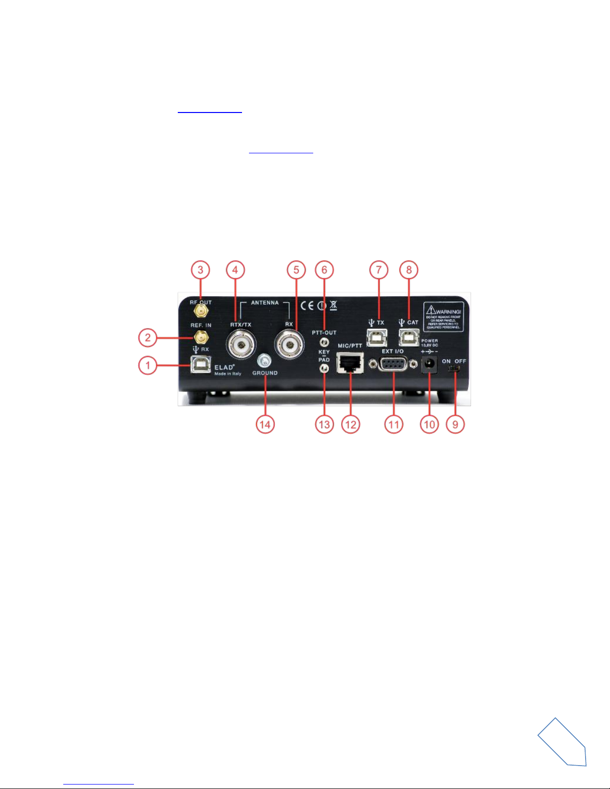
2.2 Rear Panel Description
1 - USB Receiver Data Connector
USB 2.0 port. Connect it to computer to use the SW2 software. Please use the supplied cable.
2 - Frequency Reference Input
SMA 50 Ohm connector. Apply an 10MHz 0dBm signal.
3 - RF Output Connector
SMA 50 Ohm connector. 0dBm transmission signal.
4 - Output/Input Antenna Connector
M-type 50 Ohm connector. Antenna output when using two antenna (TX). Antenna input when using
only one antenna (RTX).
5 - Input Antenna Connector
M-type 50 Ohm connector. Antenna input when using two antenna (RX).

ELAD FDM-DUO User Manual - Rev. 2.3 - 06/2016
© 2016 ELAD S.r.l. All rights reserved. No part of this document may be reproduced, published, used, disclosed or disseminated in any form or
by any means, electronic, photocopying or otherwise, without prior written permission of ELAD S.r.l.
10
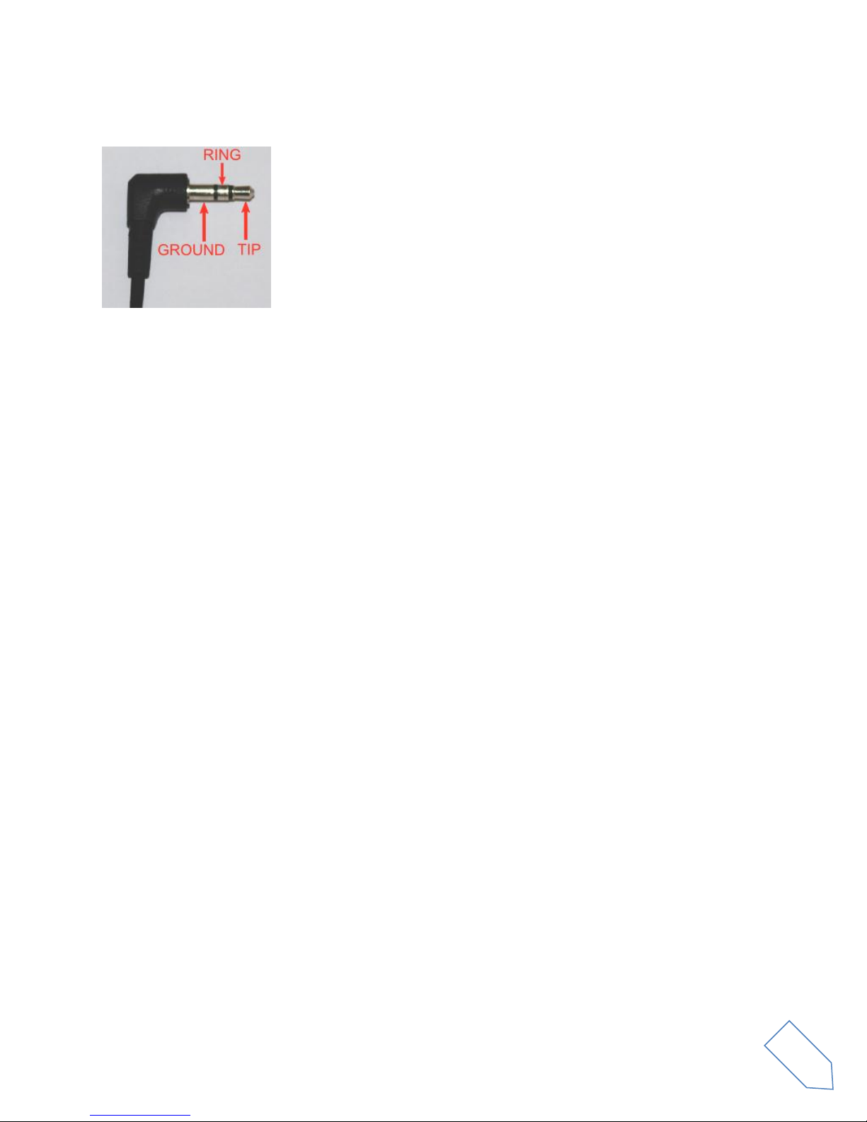
6 - PTT Output Connector
3.5mm stereo jack connector. PTT Output to connect a switch-box or an amplifier. This output is
enabled while transmitting.
RING: do not connect (reserved for future use)
TIP: PTT output (NPN Open Collector transistor, max.: 20V/200 mA)
7 - USB Audio Connector
USB 2.0 port. Connect it to the computer to access to the FDM-DUO soundcard. In input, allows fully
digitals transmissions. In output, allows to access to the received signal in a digital way.
8 - CAT USB Serial Port
USB 2.0 port. Connect it to the computer to manage the FDM-DUO through the CAT (Computer Aided
Transceiver) protocol.
9 - Power Switch
Turn on /off the FDM-DUO.
10 - Power Connector
Voltage to apply : 13.8V. Maximum current consumption : 2.5A DC.

ELAD FDM-DUO User Manual - Rev. 2.3 - 06/2016
© 2016 ELAD S.r.l. All rights reserved. No part of this document may be reproduced, published, used, disclosed or disseminated in any form or
by any means, electronic, photocopying or otherwise, without prior written permission of ELAD S.r.l.
11
11 - Expansion Port
DB9 connector for external hardware. THIS IS NOT A STANDARD SERIAL PORT.
Pin 1: SPI Latch
Pin 2: I2C SCL
Pin 3: SPI Clock
Pin 4: I2C SDA
Pin 5: Ground
Pin 6: TX Duo
Pin 7: RX Duo
Pin 8: SPI Data
Pin 9: +5V
12 –Microphone Connector
Microphone connector with PTT command. Please use the supplied one. The following image show the
connector pinout watching the FDM-DUO rear panel.
ELAD FDM-DUO User Manual - Rev. 2.3 - 06/2016
© 2016 ELAD S.r.l. All rights reserved. No part of this document may be reproduced, published, used, disclosed or disseminated in any form or
by any means, electronic, photocopying or otherwise, without prior written permission of ELAD S.r.l.
12
13 –Key/Paddle connector
3.5mm stereo jack connector.
The menu 37 (CW IN) allows to choose the input type (key or paddle).
The menu 39 (CW KEY) lets you choose the type of connection made when you use a key (i.e.,
connection on the TIP or on the RING).
The menu 40 (CW TIP) lets you choose the type of connection made when using a paddle (i.e., position
of the dot and the dash on the TIP or on the RING).
14 –Ground Connector
For better performance and safety, connect it to an earth ground using a short and wide cable.
ELAD FDM-DUO User Manual - Rev. 2.3 - 06/2016
© 2016 ELAD S.r.l. All rights reserved. No part of this document may be reproduced, published, used, disclosed or disseminated in any form or
by any means, electronic, photocopying or otherwise, without prior written permission of ELAD S.r.l.
13
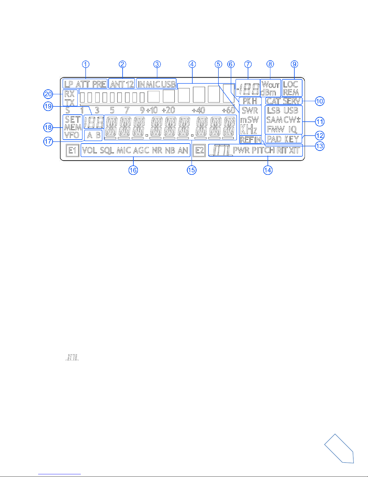
3LCD Display
1. LP: turns on when the low pass filter is active.
ATT: turns on when the attenuator is active.
2. ANT 1 2: displays the number of antennas chosen.
3. IN MIC USB: displays the input selected for transmission in SSB, AM and FM modes. Microphone
or USB TX connector.
4. METER: while receiving displays the signal strength in S-units, in transmission displays the
output power.
5. Units of measurements of the values displayed. The “S”letter of SWR is also used to indicate
that the “QuickStep”function is active.
6. PK: blinks if the ADC of reception is “overloaded”.
7. Secondary indication: while receiving displays the signal strength in dBm, in transmission
displays the output power in watt.
8. Measurement unit for the secondary indication.
9. LOC: turns on when the Main Knob is locked.
REM: turns on when the remote mode is active, turns off when the stand-alone mode is active.
10. CAT: turns on when a CAT command is received.
SERV: turns on when the service mode is enabled.
11. Operating mode.
12. Input selection for CW mode.
13. Turns on when the external frequency reference is present.
14. E2 selected function.
: reception filter setting.
PWR: transmission power setting (while transmitting).
PITCH: CW pitch frequency setting.
RIT: RIT setting.
15. Alphanumeric characters to displaying messages and numeric values.

ELAD FDM-DUO User Manual - Rev. 2.3 - 06/2016
© 2016 ELAD S.r.l. All rights reserved. No part of this document may be reproduced, published, used, disclosed or disseminated in any form or
by any means, electronic, photocopying or otherwise, without prior written permission of ELAD S.r.l.
14
16. E1 selected function.
VOL: main volume setting,
SQL: squelch setting (for FM mode),
MIC: microphone gain (while transmitting),
AGC: automatic gain control settings,
NR: noise reduction setting,
NB: noise blanker setting,
AN: auto notch setting.
17. Displays the selected VFO, A or B.
18. MEM: turns on in memory mode.
VFO: turns on in VFO mode.
SET: turns on when the setting menu is shown.
SET: turns on jointly to MEM when the VFOMEM menu is active.
19. In memory mode, displays the selected memory index.
When in the setting menu, displays the menu number.
In split, displays “SP”.
20. RX: turns on when receiving.
TX: turns on when transmitting.
ELAD FDM-DUO User Manual - Rev. 2.3 - 06/2016
© 2016 ELAD S.r.l. All rights reserved. No part of this document may be reproduced, published, used, disclosed or disseminated in any form or
by any means, electronic, photocopying or otherwise, without prior written permission of ELAD S.r.l.
15
4Quick Start
These instructions are intended only for a quick guide, detailed instructions are given later in this
manual.
4.1 First of all
To avoid having a forest of buttons and knobs as front panel, each control has different operating
modes.
The buttons can be “short pressed” or “long pressed” to activate different functions. The different
functions associated to each pressure are written in different colors just above the corresponding
button. Each top white label is associated to the “short pressure” on the button, while the lower blue
label is associated to the “long pressure”.
The knobs can be pressed as well to control a different parameter.
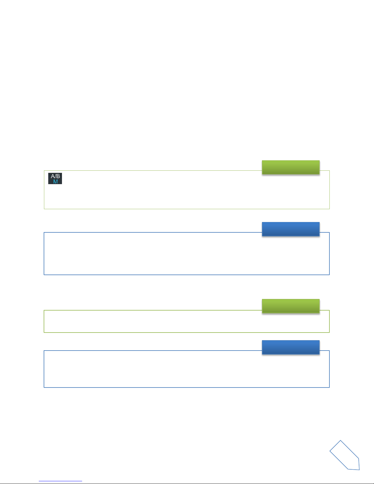
swaps A and B VFOs if “short pressed”, and swaps VFO and Memory mode if “long pressed”.
The A/B label refers to the A/B VFO swap obtained with a “short pressure”.
The M label refers to the VFO/Memory mode swap obtained with a “long pressure”.
Example
A button is “long pressed” when it is kept pressed for more than 1 sec.
This value can be changed using menu 71 ( Hold Time ) as explained in section 5.9 -
Settings Menu
List.
Valid values can vary from 500 ms to 2500 ms.
Long Pressure
The E1 knob usually controls the audio volume, but if pressed once it controls the squelch value.
Example
The tuning knob can be pressed to change the tuning step or to enter the “Digit by digit tuning
mode”.
The tuning knob operations are detailed in section 5.1.1.1 - Tuning.
Tuning

ELAD FDM-DUO User Manual - Rev. 2.3 - 06/2016
© 2016 ELAD S.r.l. All rights reserved. No part of this document may be reproduced, published, used, disclosed or disseminated in any form or
by any means, electronic, photocopying or otherwise, without prior written permission of ELAD S.r.l.
16
4.2 Reset
When first approaching a largely programmable device like FDM-DUO it is nearly unavoidable to mess
some parameters with useless values. This is not a problem and should not prevent users from trying
the different settings, since a “reset” command is available to bring back the device to the factory
settings.
4.3 A first trip
A radio like FDM-DUO has many possible application scenarios, both used as a stand-alone device, and
paired with its mate software.
In this section the simplest and most common uses will be shown, to allow a first familiarization with
FDM-DUO.
4.3.1 Reception
The first use for FDM-DUO is, clearly, reception. To do that, just connect the device to a 12V power
supply (or to a battery) and turn it on by using the back switch.
After some secs the device is in reception mode with VFO A enabled.
The reset procedure is quite simple:
•short press the MENU button
•turn the F2 knob until reading 81 DEFAULT on the display
•short press the E2 knob to show “N” on the right of DEFAULT
•turn the E2 knob to change “N” to “Y”
•short press the E2 knob
•wait for the radio reset and restart
Reset

ELAD FDM-DUO User Manual - Rev. 2.3 - 06/2016
© 2016 ELAD S.r.l. All rights reserved. No part of this document may be reproduced, published, used, disclosed or disseminated in any form or
by any means, electronic, photocopying or otherwise, without prior written permission of ELAD S.r.l.
17
The main controls are as follows:
The button is used to change to mode: at each short press the mode is changed to the next
possible mode.
Modes
The tuning is done using the main tuning knob.
It is possible to change the tuning step to an alternate value with a short pressure on the
button.
Another short pressure on the button resets the usual tuning step.
It is possible to change the tuning step to various values with a short pressure on the tuning knob.
This leads the tuning knob to select different tuning steps.
Once the desired step has been selected, another short pressure on the tuning knob will bring it back
to control the tuning, using the new selected step.
Tuning
The volume is set by the E1 knob.
The E2 knob controls the bandwidth.
Volume and bandwidth
FDM-DUO does not have the “band” concept, thus there is no “band switch”.
There are, though, some special memories holding the value of the low frequency limit of each band
as factory settings.
The “Quick Mem” mode can be used to quickly reach the wanted band; it is activated by long
pressing the button.
Press and hold the button until the display shows the wanted band.
Bands

ELAD FDM-DUO User Manual - Rev. 2.3 - 06/2016
© 2016 ELAD S.r.l. All rights reserved. No part of this document may be reproduced, published, used, disclosed or disseminated in any form or
by any means, electronic, photocopying or otherwise, without prior written permission of ELAD S.r.l.
18
By clicking on the E1 knob, it is possible to activate some useful options:
1. Audio Volume: this, as seen previously, is the default behavior;
2. Squelch Value: if activated, the related icon on the display blinks;
3. Automatic Gain Control On/Off: if activated, the AGC icon on the display blinks;
4. Automatic Gain Control Speed: it is possible to select Slow, Medium, or Fast;
5. Noise Reduction: it is possible to activate and set the level, if activated the NR icon on the
display blinks;
6. Noise Blanker: it is possible to activate and set the level, if activated the NB icon on the
display blinks;
7. Auto Notch: it is possible to activate and select two different levels of intervention; when
activated, Auto Notch detects and kills an audio persistent tone.
By clicking on the E2 knob, it is possible to activate some useful options:
1. Filter Bandwidth: this, as seen previously, is the default behavior;
2. CW Pitch: this allows to choose the preferred CW reception tone;
3. Receive Incremental Tuning On/Off;
4. Receive Incremental Tuning Value: this allows to move the reception frequency away from
the transmission frequency; this function appears only if the previous Receive Incremental
Tuning is set to On. More information can be found in section 5.1.1.3 - E2 Receiver Settings.
Enhancing Reception

ELAD FDM-DUO User Manual - Rev. 2.3 - 06/2016
© 2016 ELAD S.r.l. All rights reserved. No part of this document may be reproduced, published, used, disclosed or disseminated in any form or
by any means, electronic, photocopying or otherwise, without prior written permission of ELAD S.r.l.
19
4.3.2 Transmission
Before transmitting, always check the antenna conditions, so as to avoid problems to the PA; this must
be done on a free frequency to avoid disturbing any running QSOs.
To transmit you just have to use the PTT on the mike and speak.
In case of need it is possible to use the E1 knob to control the “Mic Gain”: a short pressure on the E1
knob lets you control the Mic Gain instead of Volume, and vice versa.
Transmission in AM, SSB and FM Mode
Transmission is driven by the CW key.
The E1 knob controls the Volume or the CW speed (in WPM). The two functions can be swapped
with a short press on the E1 knob.
Transmission in CW
When FDM-DUO is transmitting, the display changes its backlight.
Using the parameter 73 –“BACKLIGHT CHANGING” it is possible to disable this change if it is deemed
annoying, for example when operating in CW Break In mode.
Transmission

ELAD FDM-DUO User Manual - Rev. 2.3 - 06/2016
© 2016 ELAD S.r.l. All rights reserved. No part of this document may be reproduced, published, used, disclosed or disseminated in any form or
by any means, electronic, photocopying or otherwise, without prior written permission of ELAD S.r.l.
20
Due to the importance of the antenna tuning, FDM-DUO is capable to generate the signal that allows
antenna tuning.
This can be done with a long pressure on the button.
The transmission will end after a time period established by parameter 49 - “TUNE TIME” (factory set
to 10 secs) or by a new long pressure on button.
During the transmission it is possible to show different information: pressing E2 knob it is possible to
show frequency or forward power, or reflected power, or Standing Wave Ratio.
During the transmission it is possible to tune the antenna, if needed using an external ATU.
The tuning operations could be refined using parameters 55 –“TUNE POWER” and 56 – “TUNE PTT”.
Parameter 55 –“TUNE POWER” allows to select the power to be used when in tune mode, for
example reducing the power as a means to protect final power transistors when not sure of the
antenna conditions.
Parameter 56 –“TUNE PTT” allows to deactivate an external PA during tuning operations, by
disabling the PTT Out signal during tuning operations.
Antenna Tuning
Other manuals for FDM-DUO
1
Table of contents
Other ELAD Transceiver manuals


