Elbur PB 636 IV User manual
INSTRUCTION FOR USE
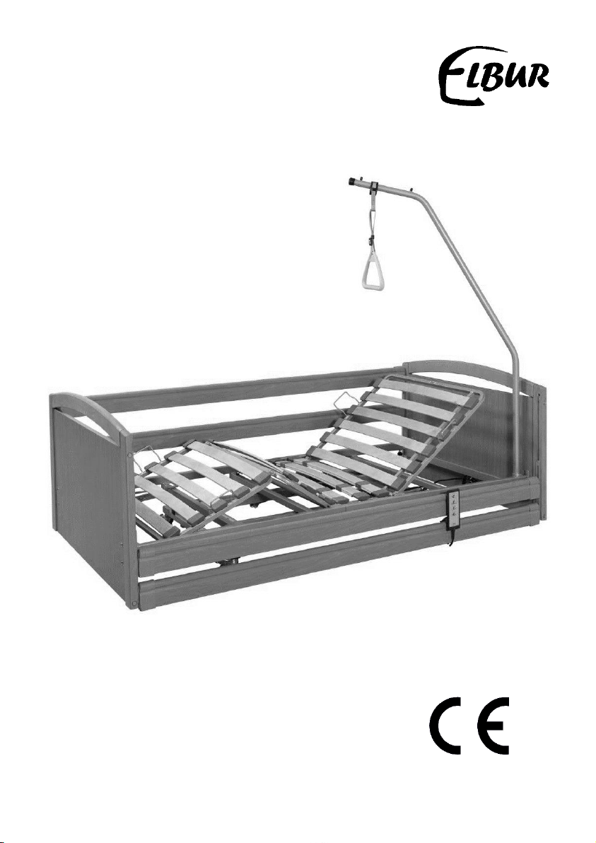
ELBUR Nursing Beds:
PB 636 IV,
PB 636 IV with axional brake


Dear Customer,
Congratulations on having chosen a quality ELBUR nursing bed which will
certainly fully meet your expectations. We would like to take this opportunity
to thank you for showing such confidence in our company and purchasing one
of our products.
Due to designing and manufacturing in accordance to the latest
technological development at the time of delivery, PB 636 IV nursing bed is
very durable and ensure essential performance. It is used to alleviate
and compensate injuries and disabilities for older, frail and handicapped
people. It also combines modern design and technical accuracy with
user-friendly handling. PB 636 IV nursing bed meets the varying needs
of patients and professional caregivers.
Based on great experience of Elbur company, we can guarantee high
quality and reliability of our products. In order to meet customer
expectations we provide wide range of bed height-adjustment. We also care
about attractive design, as well as matching furniture systems
and accessories, which can be chosen depending on the individual needs.
This instruction manual provides important information regarding safe
operation for patient, user and operator. It will help to learn about all
functions of our products and also describes: assembling, care
and maintenance of the nursing bed and operating of the adjustment
controls. Read these instructions carefully and follow them exactly in order
to provide reliable service and avoid damage or incorrect operation.
Remember to keep it for future reference.
We reserve the right to change technical specification to the ELBUR
nursing bed detailed in this instruction, without obligation to update or
replace the product.
If you have any questions, please do not hesitate to contact your local
distributor or Elbur customer service through our website. We will do our
best to fulfil your needs.
Team Elbur

Table of contents
1.0. Product description..................................................................... 6
1.1. Purpose and range of application ............................................... 6
1.2. Technical specification.............................................................. 7
1.3. Labelling of nursing beds .......................................................... 8
1.3.1. Name plates...................................................................... 8
1.3.2. Information labelling .......................................................... 8
1.3.3. Explanation of symbols used on name plate ........................... 9
2.0. Safety information ..................................................................... 9
2.1. Definitions of involved people.................................................... 9
2.2. Marking and safety signs .........................................................10
2.3. General advice and limitation of use..........................................10
2.4. Potential risks and warning messages........................................10
2.4.1. General information ..........................................................10
2.4.2. Electrical components information .......................................11
2.3.3. Information for care personnel............................................12
2.3.4. Assembly information ........................................................13
2.3.5. Service information ...........................................................13
3.0. Scope of delivery ......................................................................14
4.0. Electric components ..................................................................15
4.1. The scissor lift drive unit .........................................................15
4.2. Back rest / foot rest drive units ................................................15
4.3. Control box ...........................................................................15
4.4. Hand switch...........................................................................16
5.0. Accessories and spare parts........................................................16
6.0. Assembly .................................................................................17
6.1. Location requirements.............................................................17
6.2. Preparation ...........................................................................17
6.3. Assembly of mattress support platform on the scissor lift .............17
6.4. Location of drive units and control box for mattress support platform
..................................................................................................18

6.5. Assembly of mattress support platform drive unit –adjustment of
foot rest section ...........................................................................19
6.6. Assembly of mattress support platform drive unit –adjustment of
head rest section ..........................................................................19
6.7. Connecting electric components ...............................................20
6.8. Cable routing .........................................................................20
6.9. Testing of adjustment functions................................................21
6.10. Assembly of the end boards ...................................................21
6.11. Assembly of side rails............................................................21
6.12. Assembly of the lifting pole ....................................................22
7.0. Operating of the nursing bed ......................................................22
7.1. Electric mattress support adjustment ........................................22
7.2. Side rails operating.................................................................24
7.3. Setting the springiness of mattress support platform ...................24
7.4. Castors operating ...................................................................24
7.5. Movements of nursing beds .....................................................25
7.6. Emergency lowering of the back rest .........................................25
8.0. Maintenance.............................................................................26
8.1. Disinfecting ...........................................................................26
8.2. Cleaning and care...................................................................26
9.0. Service ....................................................................................27
9.1. Troubleshooting .....................................................................31
10.0. Transport and storage..............................................................33
11.0. Disposal.................................................................................33
12.0. Warranty ...............................................................................33
13.0. Notes
.....................................................................................33
Table of contents
Other Elbur Indoor Furnishing manuals


Popular Indoor Furnishing manuals by other brands

Regency
Regency LWMS3015 Assembly instructions

Furniture of America
Furniture of America CM7751C Assembly instructions

Safavieh Furniture
Safavieh Furniture Estella CNS5731 manual

PLACES OF STYLE
PLACES OF STYLE Ovalfuss Assembly instruction

Trasman
Trasman 1138 Bo1 Assembly manual

Costway
Costway JV10856 manual


