Elby Designs MonoWave(X) User manual

MonoWave(X) Build Guide
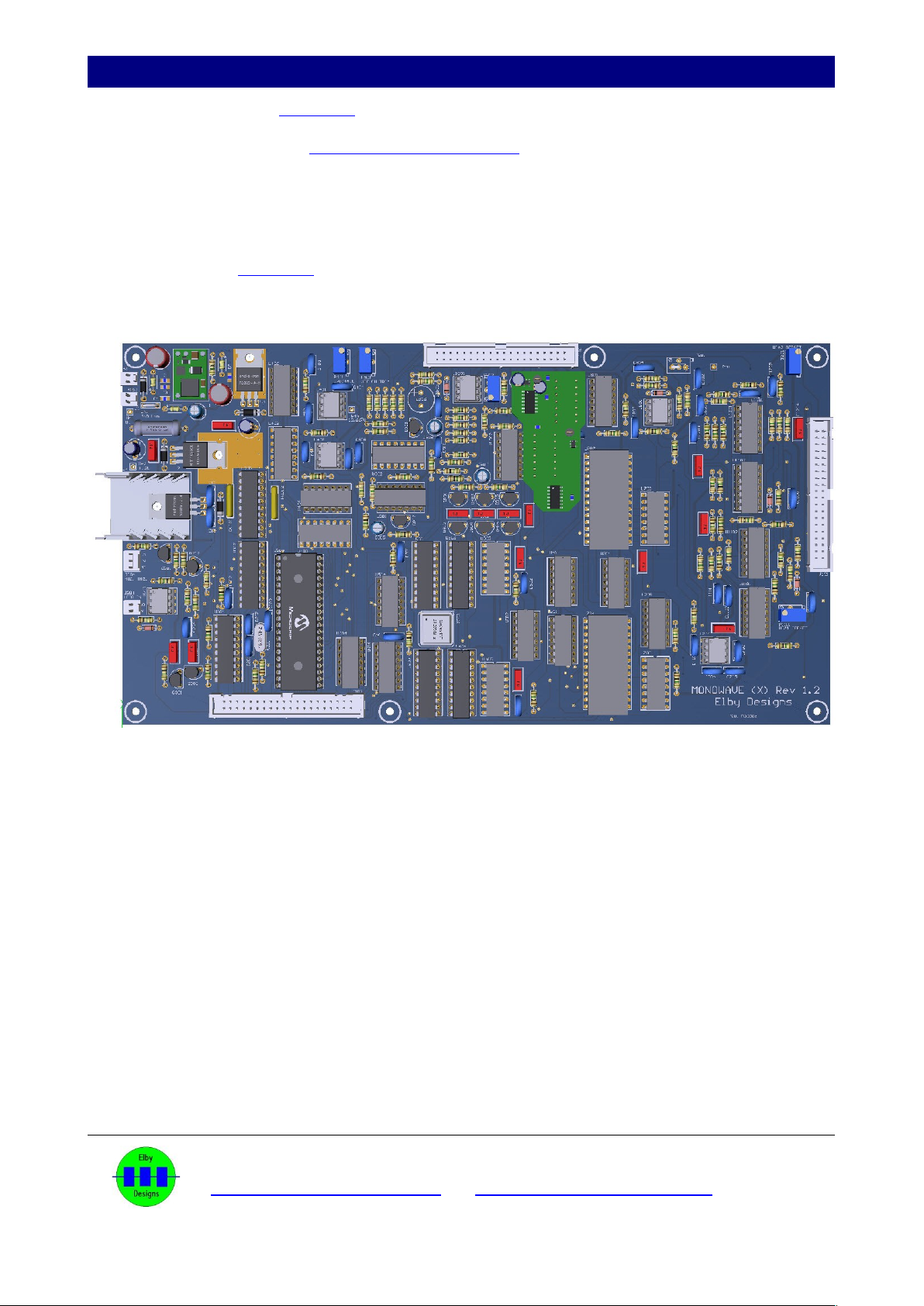
Main PCB Assembl (3D Model)
Install all components as per General Construction Notes.
When installin U4, form its le s first and then mount to the PCB with its heatsink and fixin
hardware. Once securely installed, solder in to place.
R2 should be positioned over the cut-out in the PCB and raised to be about 1-2mm clear of
the PCB.
Refer to the 3D Model for positionin of the wire links in P801 and P1001
Test Points (TPxxx) should be left clear. This will assist with ‘pokin ’ a test probe tip in to
the test point and help prevent the probe from wanderin .
ELBY Designs - Laurie Biddulph
3 Therese Street, Bridport, TAS 7262, Australia
elby-desi ns@bi pond.com http://www.elby-desi ns.com
2 of 14

MonoWave(X) Build Guide
Displa PCB Assembl (3D Model)
Refer to the PCB overlay and cut the track on the topside to P114_1 (this should already be done
in the factory).
Install all components except the 8x pushbutton switches, P120, 3x LEDs and 1x LCD plus header.
We recommend placin all the pots in to place without solderin . Then place the Front Panel over
the controls to ensure that all the pots are correctly ali ned on the Display PCB. Carefully turn the
assembly over and solder the pots in to place.
Repeat with the 2x rotary switches. Check that the switch stops are correctly located in the ‘STOP
5’ position and secure usin the nuts supplied. The nuts for these are purely to secure the ‘STOP’
plate and are not used to secure the switches to the panel.
Install P120 and check that the front set of le s on P120 are not touchin the rear set of le s. Once
satisfied, solder in to place.
Refer to the PCB overlay and fit a wire link between P114_1 and C2_1.
To help reduce the cost of the MonoWave (X) we are no lon er usin push-button switches fitted
with ‘V-brackets’.
Install but do not solder the 8x switches, ensurin that the markin s ‘C NO NO’ are visible at the
front (nearest bottom ed e of the Display PCB), and carefully offer the PCB up to the front panel.
With the panel sittin squarely to the pots (you mi ht like to fit 2 or 3 nuts to ensure the panel
remains in place) raise each switch one by one and fit a nut to the switch. Do the nut up so that it is
JUST flush with the top of the panel, the le s of the switches should still be in the Display PCB and
should finish flush with the bottom of the Display PCB. Repeat for the other 7 switches. Turn the
assembly over and rest on a suitable support to allow easy fin er access to the switches. Start at
the switches furthest from you, push a switch up until the le s are in their Display PCB locations
and the switch nut is firmly a ainst the panel. Solder tack the middle pin of the switch and repeat
for the other 7x switches. Check that all switches are suitably mounted and then solder all the
remainin le s, and finish off by reflowin the tacked centre le s.
Install the LCD as follows:-
1. Install the 4x 8mm spacers usin the 4x M2.5x16mm bolts.
2. Install, but do not solder, the header for LCD1.
3. Install LCD1 and secure usin the 4x M2.5 Nuts.
4. Check that the header is seated properly on the Display PCB and solder in to place startin
with the pads on the LCD and then movin to the pads on the Display PCB
Fit the lens mounts to the Front Panel. Install, but do not solder, the 3x LEDs.
Turn the assembly over and position the LEDs in to their respective mounts. Solder in to place.
We recommend fittin the front panel to the enclosure BEFORE mountin the Panel PCB to allow
easier access to the securin bolts.
ELBY Designs - Laurie Biddulph
3 Therese Street, Bridport, TAS 7262, Australia
elby-desi ns@bi pond.com http://www.elby-desi ns.com
3 of 14

MonoWave(X) Build Guide
Enclosure Assembl
NB: We recommend usin the 2 carry
handles supplied to attach the front panel
as they help provide protection to the
panel controls. However, fittin these front
handles will mar inally restrict access to
the two ri ht-most panel controls. If this is
not desired or you prefer a more open
front panel, then secure the panel usin
the M5 bolts and M5 nuts, mountin the
bolts from the front panel side.
Attach 2x Support Rails to the Rear Panel usin M6x 10mm Bolts and M3 nuts
Rear Panel Pre-assembly
Mount the assembly on to the 2 side panels usin 4x M3 Flan e Screws. Ensure that the
3 rows of slots on each Side Panel are at the bottom of the case. You can either mount the
flush to the outside ed e of the Side Panel or to the back of the slots, this will help protect
connectors from bein squashed and provide more clearance at the back of the unit.
ELBY Designs - Laurie Biddulph
3 Therese Street, Bridport, TAS 7262, Australia
elby-desi ns@bi pond.com http://www.elby-desi ns.com
4 of 14
MonoWave(X) Build Guide
Countin from the left, fit M3x8mm Spacers usin M3x6mm Screws at positions 3 and 29
on both Support Rails
.
Fit M3x8mm Spacers at the 12th position on the front Support Rail and 20th position on the
rear Support rail and secure usin M3x6mm Screws.
.
Fit the Front Panel usin your chosen method. Before finally ti htenin the securin bolts,
ensure that the Front Panel is centred vertically to the enclosure.
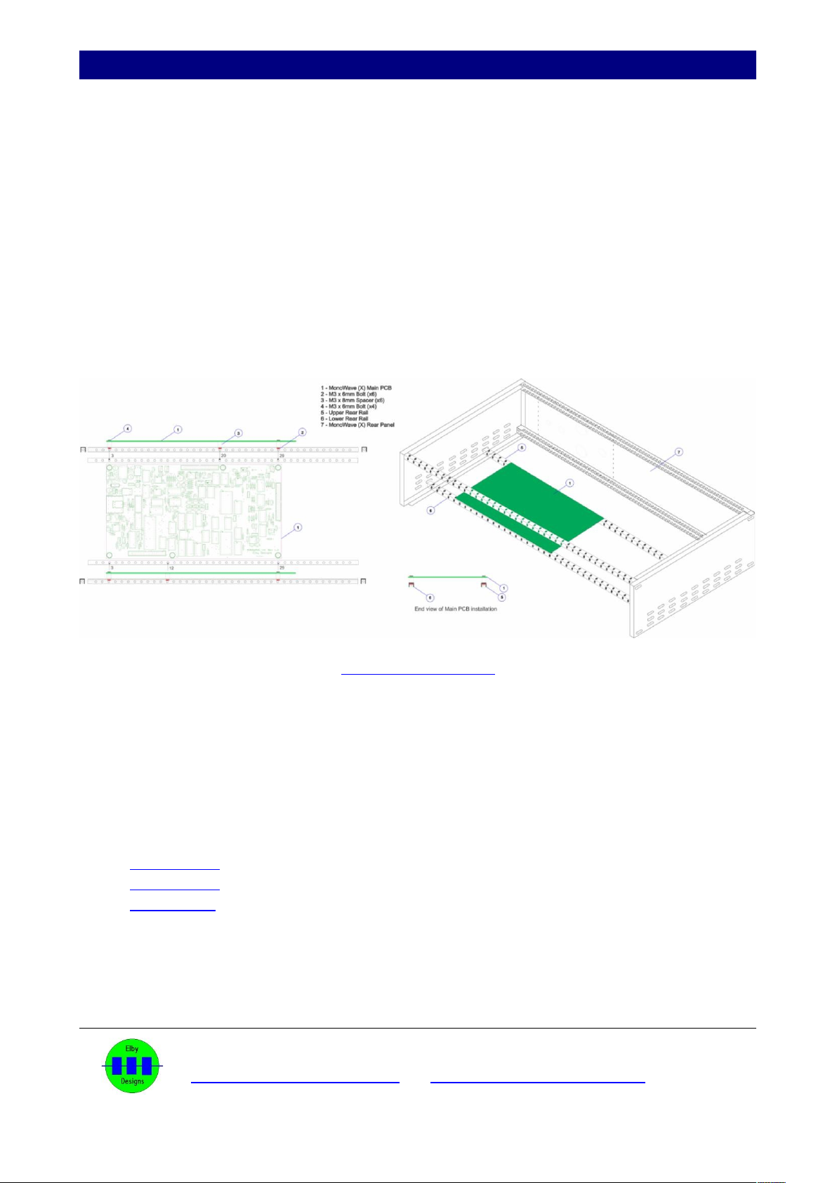
Install the main board and secure usin 4x M3x6mm Screws.
Mount the Main PCB assembly and secure to the side panels usin 4x M3 Flan ed
Screws. We recommend usin the 4th and 8th slots from the front as this will ive
clearance to work on the front panel.
Main PCB Assembly
Attach the Panel PCB to the Front Panel.
Fit the 3x IDC cables between the main board and the panel board. The central and ri ht-
hand cables should be folded to allow them to sit neatly in the chassis.
Drawin s for the 3 cables:
Cable J101
Cable J102
Cable J103
Fit the Rear Panel component assemblies and plu on to their respective headers on the
main board.
The MonoWave(X) should now be calibrated after which the top and bottom covers can be
fitted.
ELBY Designs - Laurie Biddulph
3 Therese Street, Bridport, TAS 7262, Australia
elby-desi ns@bi pond.com http://www.elby-desi ns.com
5 of 14


MonoWave(X) Build Guide
CALIBRATION
Initial Setup
Set the followin controls to maximum (CW):-
OSCILLATOR-1 OZ
OSCILLATOR-1 SUB
OSCILLATOR-2 OZ
OSCILLATOR-2 SUB
VCF-EG SUSTAIN
VCA-EG SUSTAIN
Set the followin controls minimum (CCW):-
TUNE
VCF ENVELOPE
VCF NOTE
VCF VELOCITY
VCF Q
VCF-EG ATTACK
VCF-EG DECAY
VCF-EG RELEASE
VCA-EG ATTACK
VCA-EG DECAY
VCA-EG RELEASE
VCA-EG VELOCITY
VOLUME
Set the followin controls ‘0’
DETUNE
OSCILLATOR-1 OCTAVE
OSCILLATOR-2 OCTAVE
Set VCF CUTOFF to its centre position ‘5’
Connect a MIDI Controller to MIDI IN
Connect AUDIO to a suitable amplifier
LCD Contrast
Apply power and adjust P1301 for optimum contrast.
MIDI-CV Module
Trimmer Module Function
P401 MIDI-CV V/Octave Scalin
Monitor TP401 and adjust P401 for an output of -10.667V
ELBY Designs - Laurie Biddulph
3 Therese Street, Bridport, TAS 7262, Australia
elby-desi ns@bi pond.com http://www.elby-desi ns.com
7 of 14

MonoWave(X) Build Guide
Voltage Controlled Amplifiers (VCA1 and VCA2)
Trimmer Module Function
P1111 VCA1 – Velocity Offset
P1201 VCA2 – Main Offset
Adjust P1201 full CCW
Play and release a MIDI Note near Middle C.
Adjust VOLUME for a suitable listenin level.
Adjust P1201 CW until the note just cannot be heard.
Monitor U1102_14 and adjust P1111 for 5VDC.
VCF CV Scaling
Trimmer Module Function
P901 VCF CV Scale
P902 VCF EMPHASIS Trim
Set the followin controls minimum (CCW):-
OSCILLATOR-1 SUB
OSCILLATOR-2 OZ
OSCILLATOR-2 SUB
Play and hold a MIDI Note and adjust P902 until the output just starts to self-oscillate.
Repeat to check for consistency across a ran e of MIDI Notes.
Set the followin controls to their mid-position:
VCF CUTOFF
VCF Q
Set the followin controls minimum (CCW):
VCF VELOCITY
VCF-EG SUSTAIN
Set VCF ENVELOPE to maximum (CW).
Adjust VCF-EG ATTACK and VCF-EG DECAY to ive an envelope control of the filter so
that you can hear it sweepin throu h it filter ran e.
Play and hold a low MIDI Note (e C2)
Adjust P901 so that after the envelope has complete you can just hear the note
ELBY Designs - Laurie Biddulph
3 Therese Street, Bridport, TAS 7262, Australia
elby-desi ns@bi pond.com http://www.elby-desi ns.com
8 of 14


MonoWave(X) Build Guide
Set CUTOFF FREQUENCY control to 4.
Rotate EMPHASIS control clockwise.
Filter re eneration should start with the EMPHASIS control is between 7 and 8.
If it does not, adjust the REGEN CAL trimmer
Set CUTOFF FREQUENCY control to 4.
Set EMPHASSIS to 10
Compare output with A440Hz and adjust RANGE trim for zero beats
Turn of A440 and rotate CUTOFF FREQUENCY fully clockwise
Amplitude should be fairly stable and frequency should increase to 16kHz
Rotate CUTOFF FREQUENCY and check that frequency reaches 400Hz before
re eneration stops.
Turn on A440
Adjust CUTOFF FREQUENCY for 1760Hz (2 octaves above A440)
Adjust Filter Scale trim for zero beat at A220
ELBY Designs - Laurie Biddulph
3 Therese Street, Bridport, TAS 7262, Australia
elby-desi ns@bi pond.com http://www.elby-desi ns.com
12 of 14


Other manuals for MonoWave(X)
1
Other Elby Designs Synthesizer manuals

Elby Designs
Elby Designs CGS738 Instructions for use

Elby Designs
Elby Designs EURO STAGE ES30 Instructions for use

Elby Designs
Elby Designs EURO SERGE ASM301 Instructions for use

Elby Designs
Elby Designs ASM-2 Instructions for use

Elby Designs
Elby Designs EURO-SERGE User manual

Elby Designs
Elby Designs Pixie Attache EDP WASP User manual
 User manual")
Elby Designs
Elby Designs MonoWave(X) User manual

Elby Designs
Elby Designs IF101 2Q/4Q Instructions for use

Elby Designs
Elby Designs ASM321 Instructions for use


