Elby Designs Pixie Attache EDP WASP User manual

Pixie Attaché –an EDP WASP clone
ELBY Designs –Laurie Biddulph
Kariong, NSW 2250, Australia
elby-designs@bigpond.com www.elby-designs.com
1 of 18
Pixie Attaché User Manual
Revision 2.0
March 3rd, 2018
Please note that this document is still currently under revision and we apologise for any errors or omissions.
Readers should feel free to e-mail any comments to the address given below.

Pixie Attaché –an EDP WASP clone
ELBY Designs –Laurie Biddulph
Kariong, NSW 2250, Australia
elby-designs@bigpond.com www.elby-designs.com
2 of 18
INTRODUCTION
The WASP by Electronic Dream Plant (EDP) was developed as a low-cost high-performance electronic
music synthesiser. The design of the instrument was kept as simple as possible. However every single
control on the front panel had a part to play in creating the unique sound of the WASP.
The Pixie Attaché is a clone of the EDP WASP that includes features that offer several enhancements over
the original EDP WASP including:-
a 2nd EDP WASP filter
Both the EDP WASP Filters include a 'distortion' circuit courtesy of J.Haible
a 3rd, low-pass filter
a simple Ring Modulator
a mixer providing a mix of signals in to the filter section
a mixer providing a mix of signals for the final output
2x numerically control oscillators
MIDI interface
Small attaché case design making for an ideal portable synthesizer
Block Diagram of Pixie Attaché
Pixie Attaché –an EDP WASP clone
ELBY Designs –Laurie Biddulph
Kariong, NSW 2250, Australia
elby-designs@bigpond.com www.elby-designs.com
3 of 18
SECTION I - Powering up the Pixie Attaché
The Pixie Attaché requires an external DC power source. This is normally supplied by a DC Plug Pack (*)
which should be rated for 12VDC and provide a current of 300mA or more
The Pixie Attaché has a POWER switch and a status LED to indicate when the power is ON.
(*)We recommend the use of a linear AC/DC wall-wart although switching supples can be used as well.
External Amplifier
The [LINE OUT] output (21) on the Pixie Attaché panel is suitable for driving an external amplifier while the
[HEADPHONES] output (20) can drive a pair of high-impedance headphones. Turn the [OUT LEVEL] control
to minimum before connecting to any external equipment.
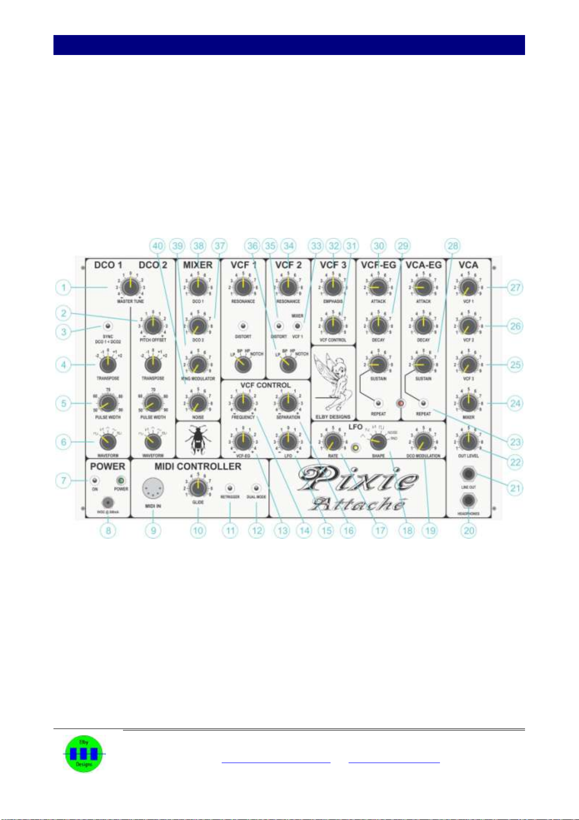
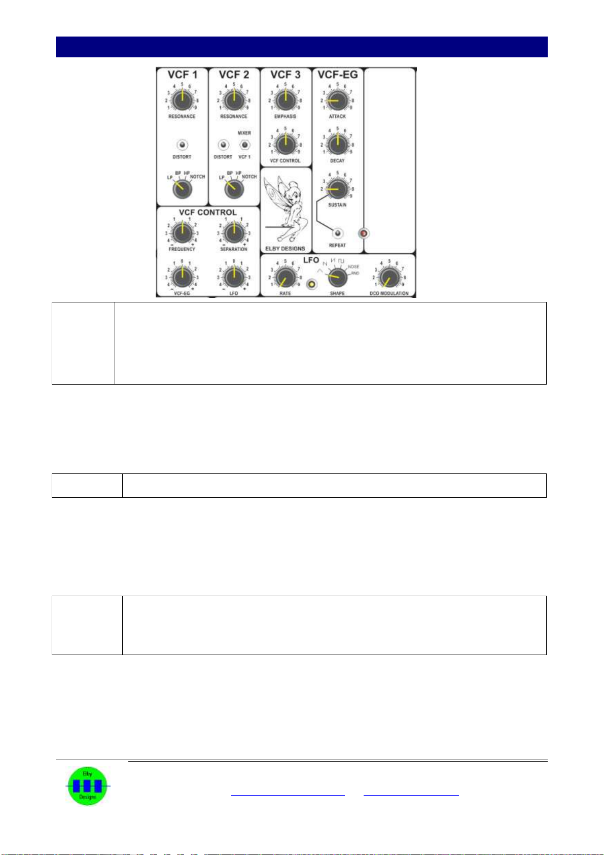
Figure 1 - Panel controls and initial starting positions
Pixie Attaché –an EDP WASP clone
ELBY Designs –Laurie Biddulph
Kariong, NSW 2250, Australia
elby-designs@bigpond.com www.elby-designs.com
4 of 18
SECTION II - The Oscillators
An oscillator can be considered to be any medium that is vibrating. A ruler
that is twanged over the edge of a desk, or a string on a guitar when plucked,
are both examples of oscillators. In the case of the Pixie Attaché the medium
involved is electricity. The oscillator is the basic building block of all
synthesisers.
In the Pixie Attaché there are two separate oscillators. The pitch of the
Oscillator (its rate of vibration) is determined by several factors:
(1) The keyboard, which controls the oscillator over a three-octave
range (C to C).
(2) The transpose control (4), which steps the oscillator over five
octaves. To see it's effect, hold down middle C and turn the
[TRANSPOSE] control (4) down to '-2', up to '+2' and then back to
'0'.
(3) The [MASTER TUNE] control (1); see Section V.
All these parameters affect the pitch of Oscillator DCO 1. In addition to having
variable pitch, the actual way in which the oscillator vibrates, known as the
wave shape or waveform, can be modified.
The five-position [WAVEFORM] selector (6) is used to switch the oscillator to
give square, sawtooth, triangular or sine wave shapes. These wave shapes
are shown in Figure 2.
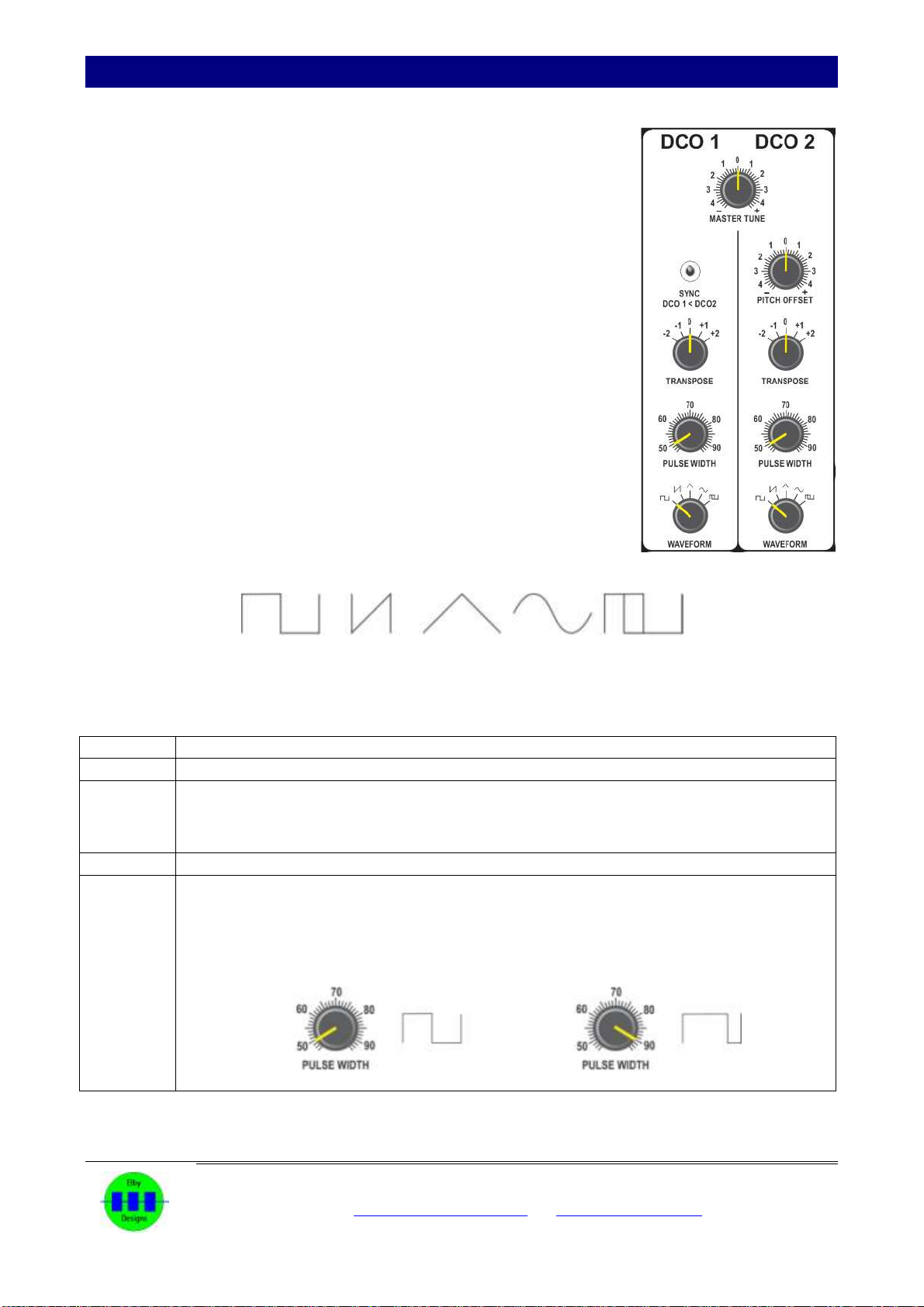
Figure 2 Oscillator Wave Shapes
A fifth waveform provides a fixed pulse-width modulated square wave.
ACTION:
Set the controls as per Figure 1. Only DCO 1 should be heard when playing a note.
ACTION:
Switch between the different wave shapes (6) and listen to the difference in tonal quality
between the waveforms. The sawtooth wave, for example, has a reedy sound while the
rectangular wave has a hollow quality to it. In addition, the rectangular wave can be modified
using the WIDTH control (5).
ACTION:
Select the square wave (6) and then turn up the [PULSE WIDTH] control (5). This has the
effect of increasing the positive period of the vibration cycle whilst increasing the period of the
negative part (see Figure 3).
As you turn up the [PULSE WIDTH] control (5) the tone of DCO 1 will become thinner with
more complex harmonics.

Pixie Attaché –an EDP WASP clone
ELBY Designs –Laurie Biddulph
Kariong, NSW 2250, Australia
elby-designs@bigpond.com www.elby-designs.com
5 of 18
Oscillator DCO 2 has the same functionality with the addition of a [PITCH OFFSET] control (2) that allows
the interval between the two oscillators to be adjusted. This could be any interval at all - a third, a fifth, a
seventh etc. Greater intervals can be obtained by changing the [TRANSPOSE] control (4).
ACTION:
Turn up the volume (37) for Oscillator DCO 2 and set up the oscillators as shown in Figure 1.
Adjust the [PITCH OFFSET] control (2) so that the two oscillators are in tune when a note is
played.
ACTION:
Turn down the volume (38) for DCO1. Rotate the [PITCH OFFSET] control (2) and note that
Oscillator DCO 2 can go up or down about 5 or 6 semitones. Therefore any required interval
between the oscillators can be obtained.
It is normally recommended to make Oscillator DCO 1 the fundamental pitch and to set
Oscillator DCO 22 to the required interval above the fundamental.
The [PITCH OFFSET] control (2) also enables the two oscillators to be very slightly detuned against one
another.
ACTION:
Set up the oscillators as in Figure 1 and fractionally increase the setting of the [PITCH
OFFSET] control (2). This gives a rich phasing affect very characteristic of the synthesiser.
There are also separate volume controls in MIXER 1 for each oscillator (37)(38).

Pixie Attaché –an EDP WASP clone
ELBY Designs –Laurie Biddulph
Kariong, NSW 2250, Australia
elby-designs@bigpond.com www.elby-designs.com
6 of 18
SECTION III - The Noise Signal
Noise is a digitally generated random sound; it doesn't have a fixed pitch like an oscillator but consists of
random frequencies that cover the audio spectrum (the range of pitches which the ear can detect).
ACTION:
Set all MIXER 1 controls (37, 38, 39 & 40) to minimum.
Turn up the [NOISE] control (40) and play any note. The characteristic hissing can be heard.
On its own this does not sound very exciting but it is particularly useful especially for
percussive sounds and sound effects.

Pixie Attaché –an EDP WASP clone
ELBY Designs –Laurie Biddulph
Kariong, NSW 2250, Australia
elby-designs@bigpond.com www.elby-designs.com
7 of 18
SECTION IV - The Ring Modulator
Ring modulation is a signal-processing function performed by multiplying two signals.
The Ring Modulator in the Pixie is an XOR function fed from the square wave outputs of the two oscillators.
For the limited case of square or pulse wave signals, this is identical to true ring modulation.
There are no controls for the Ring Modulator other than the mix level control (34) in the MIXER.
ACTION:
Set all MIXER 1 controls (37, 38, 39 & 40) to minimum.
Turn up the [RING MODULATOR] control (39) and play any note. Adjust the [PITCH] control
(2) and the [WAVEFORM] switches (6) for a variety of effects.

Pixie Attaché –an EDP WASP clone
ELBY Designs –Laurie Biddulph
Kariong, NSW 2250, Australia
elby-designs@bigpond.com www.elby-designs.com
8 of 18
SECTION V - The Controller
The Pixie Attaché replaces the original
WASP keyboard with a MIDI Interface.
This allows for a wide range of MIDI
controllers to be used such as MIDI
keyboards but also software controllers
such as used in PCs, iPads and other
software based controllers.
RETRIGGER.
When ON (11), new notes will cause the Envelope Generators to re-trigger when a new note is played
or a note is released while a 2nd is being held on..
DUAL MODE.
When OFF (12), both DCOs track the keyboard on the same note (the [PITCH] control in DCO2 allows
DCO2 to be offset from DCO1). When ON, only DCO1 plays when only a single note is being
played. When a 2nd note is received, this is assigned to the 2nd DCO. While in DUAL MODE, the
SYNC (3) switch is ignored.
GLIDE. This GLIDE (often known as PORTAMENTO) control (10) is used to increase the time taken for the
Pixie to change from one note to another. When used with both oscillators turned on an interesting
effect is achieved as the tuning of the two oscillators is offset during the period of the glide.
Pixie Attaché –an EDP WASP clone
ELBY Designs –Laurie Biddulph
Kariong, NSW 2250, Australia
elby-designs@bigpond.com www.elby-designs.com
9 of 18
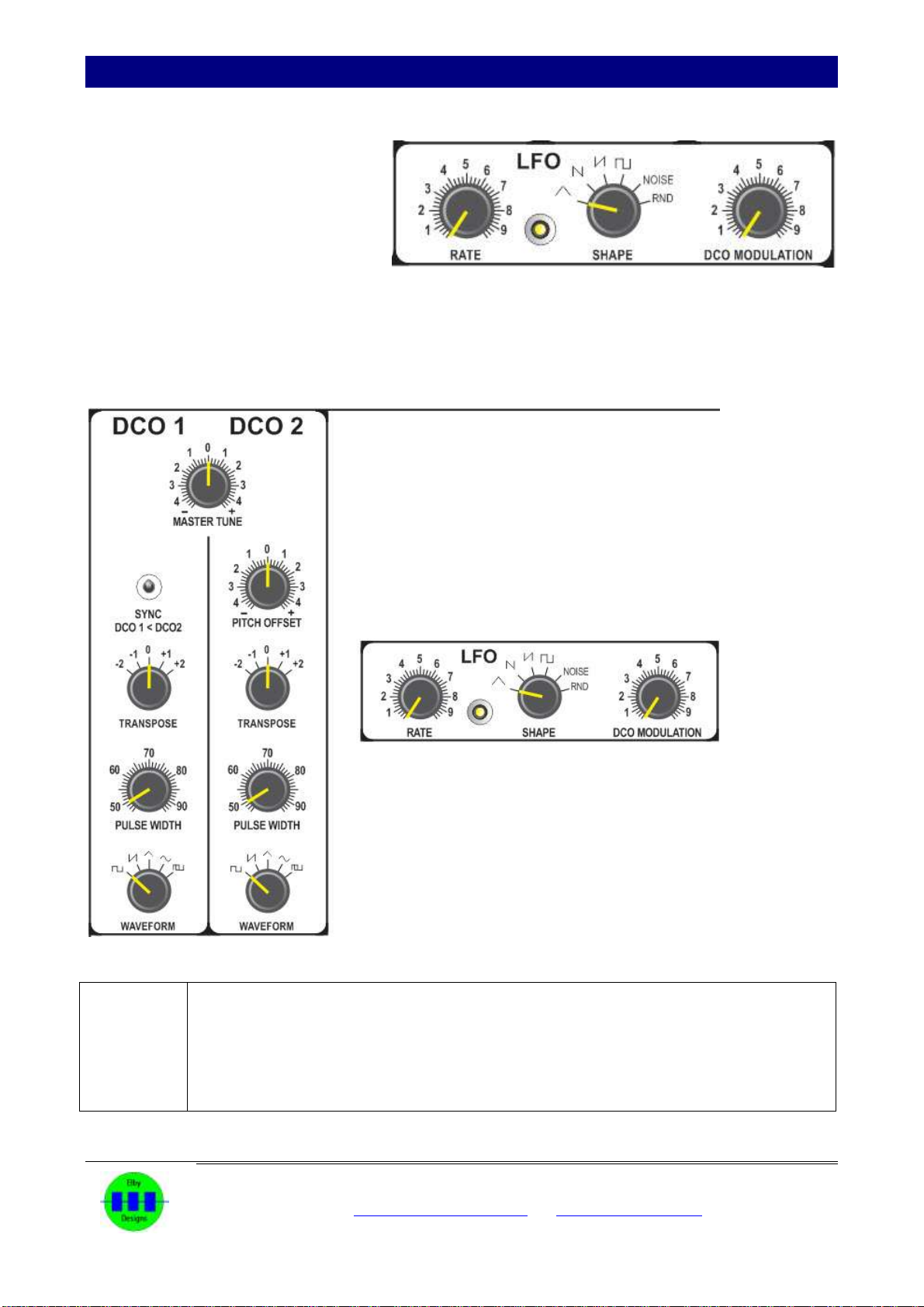
SECTION VI - The Low Frequency Oscillator
The low frequency oscillator (LFO) does
not produce any sound as such but is
used to control the two oscillators already
mentioned, and the filters.
The control knobs concerned are:-
RATE (27)
SHAPE (26)
DCO MODULATION (28)
The LFO can produce six different wave shapes selected by the [SHAPE] rotary switch (26). Reading
clockwise these are: triangle, falling sawtooth (slope), rising sawtooth (ramp), square wave, noise and
random.
ACTION:
(1) set the controls as in Figure 1.
(2) set the [DCO MODULATION] (28) to the mid position.
(3) hold any note. The pitch of DCO1 will smoothly rise and fall as represented by the
shape of the triangle wave.
(4) while still holding a note try the effects of the other modulation shapes. The speed of
modulation is increased by advancing the [RATE] control (27) while the amount of
modulation is determined by the [DCO MODULATION] control (28).
The LFO operates on both oscillators at the same time.

Pixie Attaché –an EDP WASP clone
ELBY Designs –Laurie Biddulph
Kariong, NSW 2250, Australia
elby-designs@bigpond.com www.elby-designs.com
10 of 18
In addition to modulating the frequencies
of DCO 1 and DCO 2, the LFO can be
used to sweep the frequency of the filters
VCF 1 and VCF 2. The amount of
modulation is determined by the [LFO]
control (15). If this knob is set in the mid
position it has no effect. Rotating it
clockwise will increase the amount of
modulation, the shape and speed being
determined by controls (17) and (18).
Rotating it anti-clockwise gives a similar
effect but the modulation wave shape is
inverted.
ACTION:
(1) set up as shown in Figure 1, with DCO 1 and DCO 2 in unison on '0' (4), and the [DCO 2]
control (37) turned up.
(2)
(3) Hold middle C and rotate the [LFO] control (15) clockwise and then anti-clockwise. When
it is clockwise (positive modulation) the filter will be swept by a rising sawtooth as shown.
Turning it anti-clockwise alters the sweep wave shape to a falling sawtooth. Figure 11
makes these clearer. Note that for full modulation the [RATE] control (17) has to be set
so that the LFO can cover the full frequency range of the filter.

Pixie Attaché –an EDP WASP clone
ELBY Designs –Laurie Biddulph
Kariong, NSW 2250, Australia
elby-designs@bigpond.com www.elby-designs.com
11 of 18
SECTION VII –Mixer 1
The outputs from the two oscillators are fed to a mixer along with the Noise output
and Ring Modulator outputs.
The blend of these signals can be set using the relevant 'level' controls (37, 38, 39 &
40).
The Mixer 1 output is then fed to the filters for processing. In addition, the Mixer 1
output is also fed directly to the VCA output mixer where it can be mixed in to the
final output (24).
Pixie Attaché –an EDP WASP clone
ELBY Designs –Laurie Biddulph
Kariong, NSW 2250, Australia
elby-designs@bigpond.com www.elby-designs.com
12 of 18
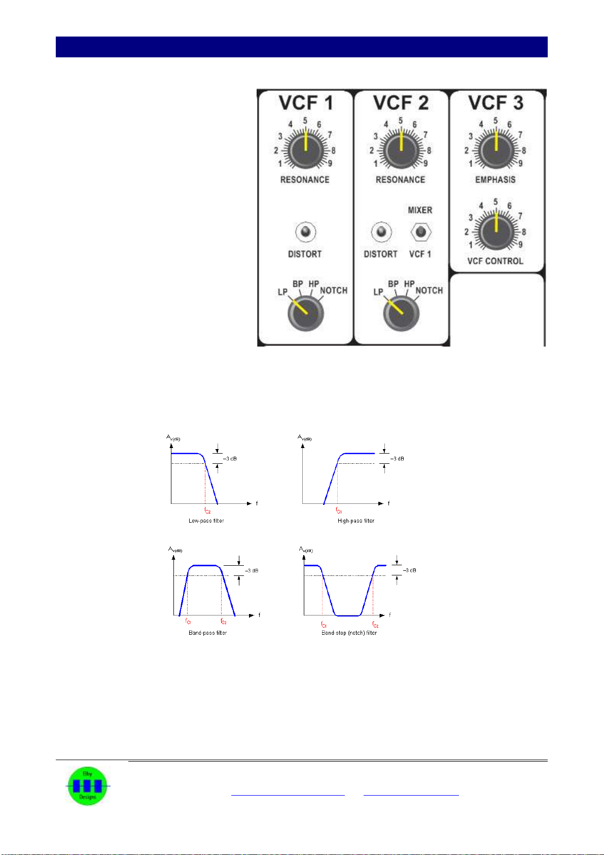
SECTION VIII - The Filters
Filters can be considered to be a complex
type of tone control. There are four types
of filtering available:
(a) Low Pass: This lets through
all parts of a signal below a
set frequency.
(b) Band Pass: This allows
frequencies through within a
certain band of frequencies
either side of a set frequency.
(c) High Pass: This allows
through all parts of a signal
above a set frequency.
(d) Notch: Also known as Band-
stop. This, basically, is the
inverse of the Band Pass
filter and supresses
frequencies within a certain
band of frequencies either
side of a set frequency.
It should be noted that there is not a sudden cut-off above, at or below the set frequency, but a gradual
decrease in volume of pitches moving away from the set frequency. This may become clearer by reference
to Figure 2.
The set frequency about which the filter operates is controlled by the [FREQUENCY] control (14).
Figure 2 - Filter types
The Pixie Attaché has 3 separate filters. VCF 1 and VCF 2 are both based on the original EDP WASP Filter
while VCF 3 is a simple low-pass filter. VCF 1 and VCF 2 also include a distortion circuit (courtesy of J.
Haible) which adds an extra dimension to the filters output.
Pixie Attaché –an EDP WASP clone
ELBY Designs –Laurie Biddulph
Kariong, NSW 2250, Australia
elby-designs@bigpond.com www.elby-designs.com
13 of 18
ACTION:
(1) Set controls as in Figure 1.
(2) Turn [DCO 1] control (38) and DCO 2 control (37) down.
(3) Turn the [MIXER] control (24) down.
(4) Turn the [NOISE] control (40) up full.
(5) Turn the [VCF 1] control (27) up full.
(6) Hold low C whilst fully rotating the [FREQUENCY] control (14).
(7) Repeat (6) with the filter in the [BP], [HP] and [NOTCH] positions.
As the noise signal can be considered to be made up of frequencies covering the whole audio spectrum, this
should give a clear idea of the effect of the filter in various modes.
The [RESONANCE] control (34) causes the filter to emphasise any signal that is close to the cut-off
frequency.
ACTION:
Repeat (6) above with the [RESONANCE] control (34) fully clockwise and then fully anti-
clockwise.
The [VCF-EG] control (13), which is explained fully in Section VIII, also introduces modulation of the filters,
but from the VCF-EG Envelope Generator. This is the reason why controls (13) and (15) are placed together
on the front panel.
In addition the Filter cut-off frequency, like the frequencies of DCO 1 and DCO 2, is also determined by the
note played on the keyboard.
ACTION:
(1) set the Pixie Attaché up as shown in Figure 1, but with the oscillators off and the noise
source on full.
(2) Play the keyboard from low C up to top C. The Filter will be heard to track the keyboard.
This is useful when using DCO 1 and DCO 2 since it means that the way the filter
modifies the wave shape of the signal will not change over the range of the keyboard.
The [SEPARATION] control (16) applies an offset control voltage to VCF 2 allowing its frequency position to
be moved from that of VCF 1.
VCF 3 is a low-pass filter. The [EMPHASIS] control (32) adjusts the 'depth' of the filtering while the [VCF
CONTROL] adjusts the 'amount' of modulation from the VCF CONTROL section.

Pixie Attaché –an EDP WASP clone
ELBY Designs –Laurie Biddulph
Kariong, NSW 2250, Australia
elby-designs@bigpond.com www.elby-designs.com
14 of 18
SECTION IX - The Envelope Generators
The Pixie Attaché has two Envelope Generators:
The VCA-EG (Voltage-Controlled Amplifier) envelope
is used to shape the output amplitude of the Pixie and
involves controls (28), (29) and (30).
The VCF-EG (Voltage-Controlled Filter) envelope is
used to sweep the filters; it involves controls (28), (29)
and (30).
These envelope generators are of the attack-decay-release-
sustain type. Figure 3 shows exactly what is happening with
the envelope.
When a note is played the envelope is triggered and the
amplitude of the envelope increases at a rate determined by
the [ATTACK] control (30). It reaches a peak then decays to a
level determined by the [SUSTAIN] control (28), decaying at a
rate set by the [DECAY] control (29). The envelope amplitude
will remain unchanged until the note is released, after which
the envelope will decay to zero at a rate set by the [DECAY]
control (29). Releasing the note before the SUSTAIN section is
reached will result in a simple ATTACK-DECAY envelope.
Figure 3 - Envelope stages. NOTE: The [DECAY] control defines BOTH falling slopes
In the VCA-EG this envelope defines the output level of the Pixie Attaché.
ACTION:
Set up the controls as in Figure 1 and experiment with the [ATTACK], [DECAY] and
[SUSTAIN] controls.
If the SUSTAIN control is turned fully anti-clockwise, the Envelope Generator can be put
into a repeat mode by turning ON the [REPEAT] switch (18). When a note is played and
held the envelope will rise to a peak level, then decay to zero, and repeat this cycle until the
note is released. The 'rate' of the repeat cycle can be adjusted using the [ATTACK] and
[DECAY] controls (29) (30). See Figure 4

Pixie Attaché –an EDP WASP clone
ELBY Designs –Laurie Biddulph
Kariong, NSW 2250, Australia
elby-designs@bigpond.com www.elby-designs.com
15 of 18
In the VCF-EG the envelope defines the control voltage for the filters.
ACTION:
(1) Set up the Pixie as in Figure 1
(2) Turn up the [DCO 2] control (37)
(3) Adjust ]PITCH OFFSET] (2)so that the oscillators are in unison.
(4) Play the keyboard. The Pixie should now be producing familiar synthesiser-like sounds.
(5) Experiment with the Filter [FREQUENCY] control (14).
(6) Experiment with the VCF-EG [ATTACK] (30), [DECAY] (29), [SUSTAIN] (28) and [VCF-
EG] (13) controls.
Figure 4 - Envelope Generators in REPEAT mode ([SUSTAIN] set to minimum)

Pixie Attaché –an EDP WASP clone
ELBY Designs –Laurie Biddulph
Kariong, NSW 2250, Australia
elby-designs@bigpond.com www.elby-designs.com
16 of 18
SECTION X - VCA
The VCA incorporates a 4-channel input mixer allowing for a mix of signals from:-
VCF1 (27)
VCF2 (26)
VCF 3 (25)
MIXER (24)
The [LINE OUT] output (21) is suitable for driving external equipment such as a mixer
or audio amplifier, while [HEADPHONES] output (20) is suitable for driving a pair of
high-impedances headphones.. The output level is adjusted using the [LEVEL] control
(22).
Inserting a jack in to the [LINE OUT] output (21) will disable the [HEADPHONES]
output (20).

Pixie Attaché –an EDP WASP clone
ELBY Designs –Laurie Biddulph
Kariong, NSW 2250, Australia
elby-designs@bigpond.com www.elby-designs.com
17 of 18
SECTION XI - SPECIFICATIONS
CONTROLLER
GLIDE
Sweep adjustable up to 3 seconds over 2 octaves
RETRIGGER
Forces all new notes to generate a GATE retrigger
DUAL MODE
Allows the keyboard to play 2 notes at the same time
CONTROLLER - OSCILLATOR Section
MASTER TUNE
approximately 5 semitones up or down
SYNC
When ON, DCO 1 will SYNChronise DCO 2 on each positive
crossing of the DCO 1 waveform
Oscillator DCO1
PULSE WIDTH
Square wave duty cycle output adjustable from 50% to 90%
WAVEFORM
Square,
Sawtooth,
Triangle,
Sine,
Modulated Pulse (approximately 4.7Hz modulation)
Oscillator DCO2
PULSE WIDTH
Square wave duty cycle output adjustable from 50% to 90%
WAVEFORM
Square,
Sawtooth,
Triangle,
Sine,
Modulated Pulse (approximately 5.3Hz modulation)
PITCH OFFSET
Detune from DCO1 by approximately one octave up or down
MIXER 1
DCO1
output from DCO1
DCO2
output from DCO2
RING MOD.
output from Ring Modulator
NOISE
output from Noise Generator
LFO –Low Frequency Oscillator
RATE
approximately 1Hz to 100Hz.
SHAPE
Triangle,
Rising sawtooth (RAMP)
Falling sawtooth (SLOPE)
Square
Noise
Random, noise signal sampled and held at LFO rate
DCO
MODULATION
Pitch of DCO1 and DCO2 can be modulated by approximately
one tone up or down

Pixie Attaché –an EDP WASP clone
ELBY Designs –Laurie Biddulph
Kariong, NSW 2250, Australia
elby-designs@bigpond.com www.elby-designs.com
18 of 18
Noise
Digitally generated 24-bit pseudo-random noise.
VCF1 & VCF2 –Voltage Controlled Filters
RESONANCE
adjustable from maximally flat to verge of oscillation
DISTORTION
On/Off control of distortion circuit
MODE
Selects filter type: - Low Pass (LP), Band Pass (BP), High Pass (HP)
and Notched (NOTCH).
The filters have 12dB slope except for Band Pass which has a 6dB slope
Turnover frequency is proportionally controlled by [LFO], [VCF-EG] or by manual
means. It is also proportionally controlled by the keyboard. Range is 3 to 16 kHz.
VCA-EG - VCA Envelope Generator
ATTACK
Linear attack rate, variable from 3mS to 2 seconds.
DECAY
Exponential decay rate, variable from 3mS to 12 seconds.
Decay is interrupted by a sustain period while the keyboard is being
touched.
SUSTAIN
The sustain signal level is adjustable from 0% to 100%
REPEAT
The repeat function causes continuous attack/decay cycles while a key
(GATE) is ON. [SUSTAIN] must be set to minimum.
VCF-EG –VCF1/VCF2 Envelope Generator
ATTACK
Linear attack rate, variable from 3mS to 2 seconds.
DECAY
Exponential decay rate, variable from 3mS to 12 seconds.
Decay is interrupted by a sustain period while the keyboard is being
touched.
SUSTAIN
The sustain signal level is adjustable from 0% to 100%
REPEAT
The repeat function causes continuous attack/decay cycles while a key
(GATE) is ON. [SUSTAIN] must be set to minimum.
VCA (Output)
Input Level Controls
Adjusts the mix of signals from VCF1, VCF2, VCF 3 and MIXER 1
OUT
Line Level output - maximum, typically, 3V pk-pk
POWER
EXTERNAL DC
12VDC. 2.5mm DC connector with Tip = +ve
CONSUMPTION
Nominally 250mA.
Table of contents
Other Elby Designs Synthesizer manuals
 User manual")
Elby Designs
Elby Designs MonoWave(X) User manual

Elby Designs
Elby Designs ASM321 Instructions for use

Elby Designs
Elby Designs EURO SERGE ASM301 Instructions for use
 User manual")
Elby Designs
Elby Designs MonoWave(X) User manual

Elby Designs
Elby Designs EURO-SERGE User manual

Elby Designs
Elby Designs ASM-2 Instructions for use

Elby Designs
Elby Designs EURO STAGE ES30 Instructions for use

Elby Designs
Elby Designs CGS738 Instructions for use

Elby Designs
Elby Designs IF101 2Q/4Q Instructions for use


