manuals.online logo
Brands
  1. Home
  2. •
  3. Brands
  4. •
  5. Lovato
  6. •
  7. Controllers
  8. •
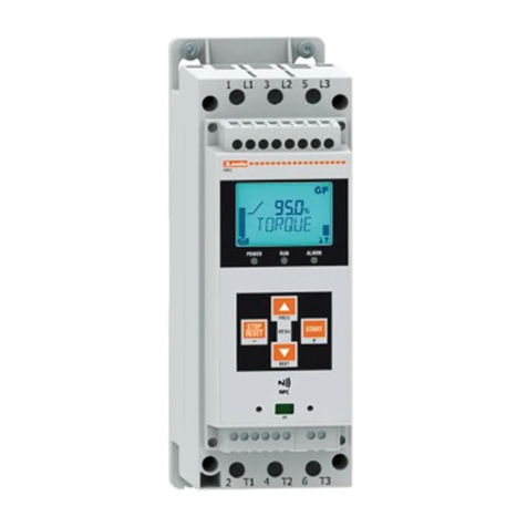
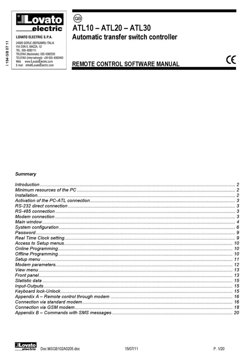
  9. Lovato ADXC 012 400 User manual

Lovato ADXC 012 400 User manual

ATTENTION
1. To prevent electrical shock, disconnect from power source before
installing or servicing.
2. Unauthorised opening of the product will void warranty.
3. For use in Pollution Degree 2 Environment.
4. The device should be configured as indicated in the connection
diagram. Do not operate the product before all connections are
completed.
5. The soft starter does not have any integrated short circuit and over-
load protection. These must be procured separately.
6. Excessive lengths of cabling should be avoided in view of EMC
considerations.
7. The ADXC has been designed as Class A equipment. Use of the
product in domestic environments can cause radio interference.
8. If capacitors for power factor correction are to be used, they must
be engaged once starting has terminated and disengaged before
stopping. During operation of thyristors (ramp-up and ramp-down),
the power factor correction equipment must be switched off and
needs to be active only during bypass.
ATTENZIONE
1. Per evitare scosse elettriche, scollegare dalla corrente prima di
installare o la manutenzione.
2. L'apertura non autorizzata del prodotto renderà nulla la garanzia.
3. Per l'uso in ambiente grado di inquinamento 2.
4. Il dispositivo deve essere configurato come indicato nello schema
di collegamento. Non utilizzare il prodotto prima che tutti i collega-
menti sono completati.
5. Il soft starter non ha nessuna protezione da cortocircuito e sovrac-
carico. Questi devono essere installati a parte.
6. I cavi non devono avere una lunghezza eccessiva per rispettare le
richieste EMC.
7. Il Soft Start ADXC è un dispositivo progettato in Classe A per uti-
lizzo in ambiente industriale. Utilizzare questo prodotto in ambiente
domestico può causare radio interferenze.
8. Nel caso sia previsto l’impiego di condensatori di rifasamento,
questi devono essere inseriti solo ad avviamento ultimato e la disin-
serzione deve essere effettuata prima dell’arresto. Durante il funzion-
amento dei tiristori (rampe di accelerazione e decelerazione) il sis-
tema di rifasamento deve rimanere disinserito e può essere connesso
solo durante la fase di bypass.
ACHTUNG
1. Trennen Sie das Gerät vor der Installation und vor
Wartungsvorgängen von der Stromversorgung, um das Risiko eines
elektrischen Schlags zu vermeiden.
2. Unerlaubtes Öffnen des Produkts führt zum Verlust der Garantie.
3. Für die Verwendung in einer Umgebung mit dem
Verschmutzungsgrad 2.
4. Das Gerät muss wie im Anschlussdiagramm angegeben konfiguri-
ert werden. Schalten Sie das Produkt nicht ein, bevor alle
Verbindungen hergestellt sind.
5. Das Sanftstartgerät besitzt keinen integrierten Kurzschluss- und
Überlastschutz. Dieser muss gesondert bereitgestellt werden.
6. Übermäßig große Kabellängen sollten aus Gründen der
Störfestigkeit vermieden werden.
7. Das ADXC ist als Gerät der Klasse A nach DIN EN 55011
eingestuft. Die Verwendung im Haushalt kann Funkstörungen zur
Folge haben.
8. Wenn die Verwendung von Kompensationskondensatoren vorge-
sehen ist, dürfen diese erst nach abgeschlossenem Startvorgang
eingeschaltet werden und die Ausschaltung muss vor dem
Stoppvorgang erfolgen. Während des Betriebs der Thyristoren
(Beschleunigungs- und Verzögerungsrampen) muss die
Kompensationsanlage ausgeschaltet bleiben und darf erst in der
Bypass-Phase zugeschaltet werden.
IMPORTANT
Lovato Electric is not to be held responsible for incorrect product
operation or damages resulting from improper use of the product
and/or use of the product outside its specified operating limits.
Products, specifications and data in this document are subject to
change without notice. The product is intended to be used by quali-
fied personnel at their own discretion and risk. Should you require
information about installation, operation or maintenance of the prod-
uct that is not covered in this document you should refer the matter
to an authorized Lovato Electric representative. The information in
this document is not considered binding on any product warranty.
IMPORTANTE
Lovato Electric non può essere ritenuta responsabile per un malfun-
zionamento o danni derivanti da un uso improprio del prodotto e/o
utilizzo del prodotto al di fuori dei suoi limiti operativi specificati.
Prodotti, specifiche e dati in questo documento sono soggette a mod-
ifiche senza preavviso.Il prodotto è destinato ad essere utilizzato da
personale qualificato a propria discrezione e rischio. Se avete bisogno
di informazioni su installazione, funzionamento o manutenzione del
prodotto non riportate in questo documento, dovete fare riferimento
al personale autorizzato Lovato Electric. Le informazioni contenute in
questo documento non sono considerate vincolanti per alcuna
garanzia sul prodotto.
WICHTIG
Lovato Electric übernimmt keine Haftung für fehlerhafte Bedienung
des Produkts sowie für Schäden, die aus unsachgemäßer
Verwendung des Produkts und/oder dem Einsatz des Produkts außer-
halb der angegebenen Grenzbetriebsdaten resultieren. Die in diesem
Dokument beschriebenen Produkte, Spezifikationen und technischen
Daten können jederzeit ohne vorherige Ankündigung geändert wer-
den. Das Produkt ist nur für die Verwendung durch qualifiziertes
Fachpersonal nach eigenem Ermessen und auf eigenes Risiko vorge-
sehen. Wenn Sie Informationen zur Installation, zum Betrieb oder zur
Wartung des Produkts benötigen, die nicht in dieser Anleitung enthal-
ten sind, wenden Sie sich mit Ihrer Frage an einen autorisierten
Vertriebspartner von Lovato Electric. Die Informationen in diesem
Dokument sind nicht bindend hinsichtlich der Produktgewährleistung.
ATTENTION
1. Avant toute installation ou intervention, déconnecter la source
d'alimentation pour éviter tout risque d'électrocution.
2. L'ouverture non autorisée du produit annule la garantie.
3. Pour exploitation en environnement de degré de pollution 2.
4. Configurer le dispositif comme indiqué dans le schéma des con-
nexions.Ne pas utiliser le produit tant que toutes les connexions ne
sont pas réalisées.
5. Le démarreur progressif n'intègre aucune protection contre les
courts-circuits et la surcharge. Ces protections doivent être
approvisionnées séparément.
6. Éviter les longueurs excessives de câblage afin de respecter les
normes de compatibilité électromagnétique.
7. De part sa conception, le démarreur ADXC se trouve répertorié
dans les équipements de Classe A. L’usage de ce produit en environ-
nement résidentiel peut provoquer des interférences radio élec-
triques.
8. S'il est prévu d'utiliser des condensateurs de correction du facteur
de puissance, il faut les activer après le démarrage et les désactiver
avant l'arrêt. Pendant le fonctionnement des thyristors (rampes d'ac-
célération et de décélération), le système de correction du facteur de
puissance doit être désactivé, il ne peut être activé que pendant la
phase de bypass.
ATENCIÓN
1. Antes de instalar o revisar el equipo, desconéctelo para evitar
descargas eléctricas.
2. La apertura del equipo sin autorización por parte del fabricante
anula la garantía.
3. Para uso en entornos con grado de contaminación 2
4. El equipo debe configurarse como se indica en el diagrama de
conexión. El equipo no debe conectarse hasta que se hayan realizado
todas las conexiones.
5. El arrancador suave no tiene protección contra cortocircuitos ni
sobrecarga. Deben instalarse independientemente.
6. Hay que evitar una longitud excesiva de los cables, con el fin de
cumplir con los requisitos de compatibilidad electromagnética.
7. El controlador ADXC es un equipo de Clase A. El uso de este pro-
ducto en entornos domésticos puede causar radiointerferencias.
8. Si fuera necesario el uso de condensadores para la corrección del
factor de potencia, estos deberán accionarse exclusivamente después
del arranque y desactivarse antes de la parada. Durante el fun-
cionamiento de los tiristores (rampas de aceleración y deceleración),
el sistema de corrección del factor de potencia tiene que permanecer
desactivado y conectarse solo durante la fase de bypass.
BEMÆRK
1. For at undgå elektrisk stød, frakobl fra strømkilde før installation
og servicering.
2. Uautoriseret åbning af produktet vil ugyldiggøre garantien.
3. Til brug i miljø med forureningsgrad 2.
4. Dette udstyr bør konfigureres som angivet i tilslutningsdiagram-
met. Sæt ikke produktet i drift før alle tilslutninger er foretaget.
5. Softstarteren har ingen indbygget beskyttelse mod kortslutning og
overbelastning. Disse skal anskaffes separat.
6. Overdreven længde på kabler bør undgås under hensyntagen til
EMC (elektromagnetisk kompatibilitet).
7. ADXC er designet og udviklet som udstyr tilhørende klasse A. Brug
af produktet i private husholdninger kan forårsage radiostøj.
8. Hvis der skal anvendes fasekompenseringskondensatorer, skal de
først tilkobles, når opstart er afsluttet og, de skal frakobles inden
stop. Under drift af tyristorer (acceleration og deceleration ramper)
skal fasekompenseringsudstyret være frakoblet og må kun være
aktivt under bypass.
WIRING DIAGRAM / SCHEMA DI COLLEGAMENTO / SCHEMA DE RACCORDEMENT / ANSCHLUSSDIAGRAMME / ESQUEMA DE CONEXIONES /
TILSLUTNINGSDIAGRAMMER
ADXC
GB
Installation Instructions - Soft starters
I Manuale d’istallazione - Avviatori statici
F Instructions d’installation - Démarreurs progressifs
D Installationsanweisungen - Soft-Motorstarter
E Instrucciones de instalación - Arrancadores estáticos
DK
Installationsinstruktioner - Softstarters
I391 GB I F D E DK 06 17
LOVATO ELECTRIC S.P.A.
24020 GORLE (BERGAMO) ITALIA
VIA DON E. MAZZA, 12
TEL. 035 4282111
TELEFAX (Nazionale): 035 4282200
TELEFAX (International): +39 035 4282400
E-mail info@
L
ovato
E
lectric.com
Web www.
L
ovato
E
lectric.com
TERMINAL DIAGRAM / DISPOSIZIONE DEI TERMINALI / DIAGRAMME DES BORNES / ANSCHLUSSBILD / DIAGRAMA DE TERMINALES / KLEMMEDIAGRAM
ADXC...400/ADXC...400 24
ADXC
®
30 60
510
085%
120s
510
20s
0
ALARM
RAMP / BYPASS
SUPPLY
F1 F2
U
t
t
T3
T1 T2 A2
A1 L3
L1 L2
Use 75OC copper (Cu)
conductors
Use 75OC copper (Cu)
conductors
ADXC...600 R2
ADXC
®
30 60
510
085%
120s
510
20s
0
ALARM
RAMP / BYPASS
SUPPLY
12 11/21 24 F1 F2 ST
U
t
t
T3
T1 T2 A2
A1 L3
L1 L2
Pozidriv Bit 0
0.6Nm (5.3 lb.in)
Pozidriv Bit 2
2.5Nm (22 lb.in)
2.5 ... 10mm2
2 x 2.5 .... 4mm2
AWG 6 ... 14
AWG 2 x 20 ...
L1, L2, L3:
Line connections
T1, T2, T3: Load connections
A1, A2:
Control voltage
8.0mm
Rigid:
AWG 10 ... 14
0.5 ... 1.5mm2
AWG 10 ... 18
6.0mm
Pozidriv Bit 0
0.6Nm (5.3 lb.in)
Pozidriv Bit 2
2.5Nm (22 lb.in)
2.5 ... 10mm2
2 x 2.5 .... 4mm2
AWG 6 ... 14
AWG 2 x 20 ...
L1, L2, L3: Line connections
T1, T2, T3: Load connections
A1, A2: Supply voltage
11, 12: Alarm indication (Normally Closed, NC)
21, 24: Top of Ramp indication
(Normally Open, NO)
ST: Start / Stop signal
8.0mm
Rigid:
AWG 10 ... 14
0.5 ... 1.5mm2
AWG 10 ... 18
6.0mm
6.0mm
11, 12, 21, 24:
0.05 ... 1.5mm2
AWG 14... 12
0.45Nm (4lbin)
Pozidriv 0
ADXC...400 ADXC...400 24 ADXC...600 R2
DIMENSIONS (MM) / DIMENSIONI (MM) / DIMENSIONS (MM) / ABMESSUNGEN (MM) / DIMENSIONES (MM) / MÅL (MM)
45 109.8
106
115
105
125
Ø5.2
❶
❶
❶ 2 x M5
35mm
DIN rail
IEC/EN
60715
ADXC
®
30 60
510
085%
120s
510
20s
0
ALARM
RAMP/ BYPASS
SUPPLY
F1 F2
U
t
t
ADXC012...ADXC032...
45
125
35mm
DIN rail
IEC/EN
60715
153.8
150
36
105
123
121
6.46
❶ 2 x M5
❶
❶
4.8
5.2
132
ADXC
®
30 60
510
085%
120s
510
20s
0
ALARM
RAMP/ BYPASS
SUPPLY
12 11/21 24 F1 F2 ST
U
t
t
ADXC037...ADXC045...
SOFT STARTER SETTING / CONFIGURAZIONE DELL’AVVIATORE STATICO / CONFIGURATION DU DÉMARREUR PROGRESSIF / EINSTELLVORGANG FÜR DAS
SANFTSTARTGERÄT / CONFIGURACIÓN DEL ARRANCADOR SUAVE / NDSTILLINGSPROCEDURE FOR SOFTSTARTER
ADXC
®
30 60
510
085%
120s
510
20s
0
ALARM
RAMP / BYPASS
SUPPLY
F1 F2
U
t
t
T3
T1 T2 A2
A1 L3
L1 L2
Step 1: Adjust Starting Voltage (0 - 85%)
Fase 1: Regolare la tensione iniziale
Phase 1: Réglage de la tension initiale
Schritt 1: Anfangsspannung einstellen
Paso 1: Ajuste de la tensión inicial
Trin 1: Justér den indledende spænding
Step 2: Adjust Starting Time (1-20s)
Fase 2: Regolare il tempo di accelerazione
Phase 2: Réglage du temps d'accélération
Schritt 2: Anlaufzeit einstellen
Paso 2: Ajuste del tiempo de rampa ascendente
Trin 2: Justér starttiden
Step 3: Adjust Stopping Time (0 - 20s)
Fase 3: Regolare il tempo di decelerazione
Phase 3: Réglage du temps de décélération
Schritt 3: Auslaufzeit einstellen
Paso 3: Ajuste del tiempo de rampa descendente
Trin 3: Justér sluktiden
Application Initial Voltage Time / Tempo Time / Tempo
Applicazione Tensione iniziale Ramp-up (s)
Ramp-down (s)
Hydraulic lifts 40% 2 0
Piston compressor 40% 3 0
Screw compressor 50% 10 0
Scroll compressor 40% 1 0
Low inertia fan 40% 10 0
High inertia fan 40% 15 – 20 0
Pump 40% 10 10
Centrifugal blower 40% 5 0
Conveyor 50% 10 5
STATUS INDICATION LEDS / LED DI INDICAZIONE STATO
IMPORTANT
Lovato Electric ne peut être tenu responsable d'une exploitation
incorrecte du produit ou d'avaries résultant d'une utilisation incor-
recte du produit et/ou hors des tolérances de fonctionnement spéci-
fiées.
Les produits, caractéristiques et données décrites dans le présent
document peuvent changer sans préavis. L'utilisation de ce produit
est destinée à un personnel qualifié qui l'exploite à sa guise et à ses
propres risques. Pour plus amples informations concernant l'instal-
lation, le fonctionnement ou la maintenance du produit et ne figurant
pas dans ce document, consulter un concessionnaire agréé Lovato
Electric. Les informations contenues dans ce document ne con-
stituent une obligation de garantie de quelconque nature du produit.
IMPORTANTE
Lovato Electric no se responsabiliza del uso incorrecto del producto
o de los daños ocasionados por un uso incorrecto del mismo y /o por
el uso del producto sin tener en cuenta los límites de funcionamiento
especificados.
Los equipos, especificaciones y datos recogidos en este documento
están sujetos a cambios sin previo aviso. El equipo debe usarse por
personal cualificado y bajo su responsabilidad y riesgo. En caso de
necesitar más información sobre la instalación, funcionamiento o
mantenimiento del equipo que no se refleje en este documento, pón-
gase en contacto con un distribuidor autorizado de Lovato Electric. La
información detallada en este documento no se considera vinculante
en ninguna garantía del producto.
VIGTIGT
Lovato Electric kan ikke holdes ansvarlig for ukorrekt anvendelse af
produktet eller skader opstået ved ukorrekt brug og/eller efter brug af
produktet til andet end de specificerede driftsbestemmelser.
Produkter, specifikationer og data i dette dokument kan ændres uden
varsel. Produktet er beregnet til anvendelse af uddannet personale
efter eget skøn og risiko. Hvis du har brug for oplysninger om instal-
lation, drift eller vedligeholdelse af produktet, der ikke er dækket af
nærværende dokument, bør du rette henvendelse til en autoriseret
repræsentant fra Lovato Electric. Informationen i nærværende doku-
ment anses ikke for bindende for nogen produktgaranti.
Mains voltage
Normal operating conditions / Condizioni di funzionamento normale
Green LED
Red LED
Control voltage
Starter output
Relay contact (Bypass)
for ADXC...600R2
Relay contact (Alarm)
for ADXC...600R2
1 sec 1 sec
< 1 sec
1 sec
>=1 sec
FUNCTION IND. COLOUR STATUS
FUNZIONE SIGLA COLORE STATO
Power supply SUPPLY Green Constanly on
Alimentazione Verde Fisso
Ramp / Bypass relay RAMP/BYPASS Yellow Flashing / Constantly on
Rampa / Relè di Bypass Giallo Lampeggiante / Fisso
Alarm conditions ALARM Red Flashing / Constantly on
Allarme Rosso Lampeggiante / Fisso
I391 GB I F D E DK 06 17
SHORT CIRCUIT PROTECTION (ACCORDING TO IEC/EN 60947-4-2 AND UL508) / PROTEZIONE DA CORTO CIRCUITO (SECONDO LE NORME
IEC/EN 60947-4-2 E UL508) / PROTECTION CONTRE LES COURTS-CIRCUITS (SELON IEC/EN 60947-4-2 ET UL508) / KURZSCHLUSSSCHUTZ
(GEMÄSS IEC/EN 60947-4-2 UND UL508) / PROTECCIÓN CONTRA CORTOCIRCUITOS (SEGÚN IEC/EN 60947-4-2 Y UL508) /
KORTSLUTNINGSBESKYTTELSE (IHT. IEC/EN 60947-4-2 OG UL508)
CURRENT / POWER RATINGS AT 40˚C - DATI DI CORRENTE / POTENZA A 40°C
ALARM INDICATION / INDICAZIONE DI ALLARME / INDICATION D’ALARME / ALARMANZEIGE / INDICACIÓN DE ALARMA / ALARMANGIVELSE
Wrong phase sequence / Errata sequenza fase
(2 flashes / 2 lampeggi)
Overvoltage condition - (line voltage) / Sovratensione - (tensione di linea)
(3 flashes / 3 lampeggi)
Undervoltage condition - (line voltage) / Sottotensione - (tensione di linea)
(3 flashes / 3 lampeggi)
Ramp-Up time - Tempo di accelerazione
(> 1 sec.) (6 flashes / 6 lampeggi)
Overcurrent condition (during bypass) / Sovracorrente (durante bypass)
(> le +15%) (8 flashes / 8 lampeggi)
Overcurrent condition (during ramping) / Sovracorrente (durante accelerazione)
(>4x le) (5 flashes / 5 lampeggi)
ALARM LED FLASHING SEQUENCE / SEQUENZA LAMPEGGIANTE LED ALLARME (red / rosso)
Co-ordination Type 1 (UL508) – Time delay fuses /
Co-ordinamento Tipo 1 (UL508) – Fusibili ritardati
Type Max. Fuse Size / UL/CSA Class / Current / Max. Voltage /
Tipo Taglia fus. max Classe UL/CSA Corremte Tensione max
[A] [kA] [VAC]
ADXC 012... 20 RK5 5400 / 600
ADXC 016... 20 RK5 5400 / 600
ADXC 025... 25 RK5 5400 / 600
ADXC 032... 35 RK5 5400 / 600
ADXC 037... 50 RK5 5400 / 600
ADXC 045... 50 RK5 5400 / 600
Co-ordination Type 1 – Manual motor starters /
Co-ordinamento Tipo 1 – Interruttori salvamotori
Type Size / Current / Max voltage /
Tipo Taglia Corremte Tensione max
[kA] [VAC]
ADXC 012... SM1B 44 12.5 400 / 600
ADXC 016...
ADXC 025... SM1B 56 12.5 400 / 600
ADXC 032...
ADXC 037... SM3A 84 25 400 / 600
ADXC 045...
Co-ordination Type 2 IEC/EN 60947-4-2 - Semiconductor fuses /
Co-ordinamento Tipo 2 IEC/EN 60947-4-2 – Fusibili a semiconduttore
Type Max. Fuse Size / Class / Current / Max. Voltage /
Tipo Taglia fus. max Classe Corremte Tensione max
[A] [kA] [VAC]
ADXC 012... 35 aR 5 400 / 600
ADXC 016... 35 aR 5 400 / 600
ADXC 025... 60/63 aR 5 400 / 600
ADXC 032... 60/63 aR 5 400 / 600
ADXC 037... 125 aR 5 400 / 600
ADXC 045... 125 aR 5 400 / 600
Type IEC Rated Current Motor power IEC/UL-CSA - Potenza motore IEC/UL-CSA
Tipo Corrente nominale IEC 220 - 240 VAC 380 - 415 VAC 440 - 480 VAC 550 - 600 VAC
ADXC 012 400 / ADXC 012 400 24 12 AAC 3 kW/ 3 HP 5.5 kW/ 5 HP –– ––
ADXC 016 400 / ADXC 016 400 24 16 AAC 4 kW/ 5 HP 7.5 kW/ 7.5 HP –– ––
ADXC 025 400 / ADXC 025 400 24 25 AAC 5.5 kW/ 7.5 HP 11 kW/ 10 HP –– ––
ADXC 032 400 / ADXC 032 400 24 32 AAC 9 kW/ 10 HP 15 kW/ 15 HP –– ––
ADXC 037 400 / ADXC 037 400 24 37 AAC 9 kW/ 10 HP 18.5 kW/ 20 HP –– ––
ADXC 045 400 / ADXC 045 400 24 45 AAC 11 kW/ 15 HP 22 kW/ 25 HP –– ––
ADXC 012 600 R2 12 AAC 3 kW/ 3 HP 5.5 kW/ 5 HP 5.5 kW/ 7.5 HP 9 kW/ 10 HP
ADXC 016 600 R2 16 AAC 4 kW/ 5 HP 7.5 kW/ 7.5 HP 9 kW/ 10 HP 11 kW/ 15 HP
ADXC 025 600 R2 25 AAC 5.5 kW/ 7.5 HP 11 kW/ 10 HP 11 kW/ 15 HP 20 kW/ 20 HP
ADXC 032 600 R2 32 AAC 9 kW/ 10 HP 15 kW/ 15 HP 18.5 kW/ 20 HP 22 kW/ 30 HP
ADXC 037 600 R2 37 AAC 9 kW/ 10 HP 18.5 kW/ 20 HP 22 kW/ 25 HP 30 kW/ 30 HP
ADXC 045 600 R2 45 AAC 11 kW/ 15 HP 22 kW/ 25 HP 22 kW/ 30 HP 37 kW/ 40 HP
LED AND RELAY STATUS IN ALARM CONDITIONS / STATO DI LED E RELÈ IN FASE DI ALLARME
N° of flashes Description of fault Relay contact position Action
No. lampeggi Descrizione gausto Posizione contatto relè Azione
Alarm (11, 12) Bypass (21, 24)
2 Wrong phase sequence Open Open Physical change

Errata sequenza fase Aperto Aperto Intervento utente

3 Line voltage out of range Open Open Auto reset with 5min recovery
Tensione di linea fuori limiti Aperto Aperto Auto-reset con 5min di recupero
4 Frequency out of range Open Open Auto reset with 5min recovery
Frequenza fuori limiti Aperto Aperto Auto-reset con 5min di recupero
5 Overcurrent (>4•Ie during ramping) Open Open Auto reset with 5min recovery

Sovraccorrente (>4•Ie in fase di rampa/accelerazione) Aperto Aperto Auto-reset con 5min di recupero

6 Ramp up time lapsed Open Open Auto reset with 5min recovery

Fuori tempo di accelerazione Aperto Aperto Auto-reset con 5min di recupero

7 Over temperature Open Open Auto reset with 5min recovery
Sovratemperatura Aperto Aperto Auto-reset con 5min di recupero
8 Overcurrent (1.15•Ie for 1s during bypass) Open Closed User intervention to stop the starter

Sovraccorrente (1,15•Ie per 1s in fase di bypass) Aperto Chiuso Intervento utente per arresto avviatore

9 Supply voltage unbalance (difference >10% Ue Open Open Auto reset with 5min recovery assuming all phases are connected
between 2 phase connected to L1-L2-L3) Aperto Aperto Auto-reset con 5min di ricupero assumendo che tutte le fasi sono
Squilibro tensione motore (differenza >10% Ue collegate
tra 2 fasi collegate di L1-L2-L3)
Immediate user intervention is required to restore the starter operation by changing the wrong connections of the phase sequence and resetting the alarm.
L’intervento immediato dell’utente è necessario per ripristinare il funzionamento dell’avviatore modificando le connessioni per errata sequenza fase e resettando l’allarme.
User intervention is required to restore the starter operation by switching the starter off and on again.
L’intervento dell’utente è necessario per ripristinare l’avviatore effettuando lo spegnimento e nuova accensione dell’avviatore.
Alarm tripping is for reference and indication purposes only; it should not be considered as means of protection. The bypass relays remain closed even in alarm conditions.
Immediate user intervention is required to switch off the starter who then must verify the eventual causes of the alarm.
La funzionalità dell’allarme è puramente informativa; non va considerata come mezzo di protezione. I relè di bypass rimangono chiusi anche in condizioni di allarme.
Il pronto intervento dell’utente è necessario per spegnere l’avviatore il quale dovrà verificare eventuali cause dell’allarme.
2L1L
1L2L
3L3L
L3
L2
L1
Mains voltage
Green LED
Red LED
Control voltage
Starter output
Relay Contact (Bypass)
Relay contact (Alarm)
< 1 sec ≥1 sec
1sec.
5 mins recovery
5 mins recovery
Mains voltage
Green LED
Red LED
Control voltage
Starter output
Relay Contact (Bypass)
Relay contact (Alarm)
< 1 sec ≥1 sec
1sec.
5 mins recovery
5 mins recovery
Mains voltage
Green LED
Red LED
Control voltage
Starter output
Relay Contact (Bypass)
Relay contact (Alarm)
5min recovery
Green LED
Red LED
Control voltage
Starter output
Relay contact (Bypass)
Relay contact (Alarm)
Mains voltage
Overcurrent Condition
(>4xIe)
User Intervention required to reset device by
switching OFF and re-applying power to the soft starter
1 sec 1 sec 1 sec
5min 5min LED continues flashing
5min recovery Alarm does not
self-recover
Two Consecutive
Alarms
Green LED
Red LED
Control voltage
Starter output
Relay contact (Bypass)
Relay contact (Alarm)
Mains voltage
User Intervention required to reset device by
switching OFF and re-applying power to the soft starter
1 sec 1 sec
5min 5min
LED continues flashing
5min recovery 5min recovery
>1 sec
>1 sec
>1 sec
Alarm does not
self-recover
Two Consecutive
Alarms
Green LED
Red LED
Control voltage
Starter output
Relay contact (Bypass)
Relay contact (Alarm)
Mains voltage
Overcurrent condition
(>Ie + 15%)
1 sec
5mins
Protection Co-ordination,
Type 1 vs Type 2
Type 1 protection implies that
after a short circuit, the device
will no longer be in a functional
state.
In Type 2 co-ordination the
device will still be functional
after the short circuit. In both
cases, however the short circuit
has to be interrupted. The fuse
between enclosure and supply
shall not open. The door or
cover of the enclosure shall not
be blown open. There shall be
no damage to conductors or
terminals and the conductors
shall not separate from
terminals. There shall be no
breakage or cracking of
insulating bases to the extent
that the integrity of the
mounting of live parts is
impaired. Discharge of parts or
any risk of fire shall not occur.
The product variants listed in
the UL508 table hereunder are
suitable for use on a circuit
capable of delivering not more
than 5,000A rms Symmetrical
Amperes, 600 Volts maximum
when protected by class RK5
fuses. It indicates the maximum
allowed ampere rating of the
fuse.
Coordinazione protezioni,
Tipo 1 vs Tipo 2:
Tipo 1 presuppone che dopo un
corto circuito, il dispositivo non
sarà più in uno stato funzionante.
Nel tipo 2 il coordinamento del
dispositivo sarà ancora funzio-
nante dopo il corto circuito. In
entrambi i casi, tuttavia il corto
circuito deve essere interrotto. Il
fusibile non è aperto. La porta o
il coperchio del contenitore non
deve essere aperto. Non devono
essere danneggiati i conduttori e
i terminali. Non ci devono
essere rotture e screpolature
delle basi isolanti nella misura in
cui l'integrità del montaggio e
delle parti in tensione è alterata.
Rotture o rischio di incendi non
devono avvenire.
Le varianti di prodotti elencati
nella tabella UL508 che segue
sono adatti per l'uso su un
circuito in grado di fornire non
più di 5.000A rms simmetrici,
600 volt massimo, se protetto
da fusibili classe RK5. Indica
l’amperaggio massimo consen-
tito del fusibile.
Coordination de protection,
comparatif Type 1 et Type 2:
La protection de type 1 implique
qu'après un court-circuit, le
n'est plus à l'état fonctionnel.
En protection de type 2, le
dispositif demeure à l'état
fonctionnel après court-circuit.
Cependant, dans les deux cas le
circuit doit être protégé. Le
fusible entre le boîtier et
l'alimentation doit être intègre.
La trappe ou le couvercle de
l'enceinte ne doivent pas avoir
été soulevés par l'air rejeté. Les
conducteurs ou les bornes ne
doivent présenter aucune avarie
et les conducteurs ne doivent
pas être désolidarisés des
bornes. Il ne doit y avoir ni
rupture ni fissuration des bases
isolantes susceptibles d'affecter
l'intégrité du montage des
parties sous tension. Il ne peut y
avoir aucune décharge des
pièces ni aucun risque
d'incendie.
L'utilisation des variantes du
produit (voir tableau UL508
suivant) convient à un circuit
protégé par fusibles classe RK5,
délivrant 5,000 A (eff.) symétri-
ques ou moins à 600 V maxi-
mum. Il spécifie l'ampérage
maximal autorisé pour le
Schutzkoordinierung,
Typ 1 gegen Typ 2:
Typ-1 bedeutet, dass sich das
Gerät nach einem Kurzschluss
nicht länger im Funktionszustand
befindet.
Beim Typ 2 ist das Gerät nach
einem immer noch einsatzbereit.
In beiden Fällen muss der
Kurzschluss beendet sein. Die
Testsicherung zwischen Gehäuse
und Versorgung darf nicht
ausgelöst haben. Die Tür bzw.
Abdeckung des Gehäuses darf
nicht aufgesprengt werden. An
den Leitern oder Anschluss-
klemmen dürfen keine Schäden
entstanden sein und die Leiter
dürfen sich nicht von den
Anschluss-klemmen gelöst
haben. Die Isolierung darf nicht
so weit aufgebrochen oder
gerissen sein, dass die
Betriebssicherheit der Halterung
von stromführenden Teilen
beeinträchtigt ist. Es dürfen
keine Teile weggeschleu-dert
werden und es darf keine
Brandgefahr bestehen. Die in der
nachstehenden UL508 Tabelle
auf-geführten Varianten sind
geeignet für den Einsatz in einem
Stromkreis, der bei Schutz durch
Sicherungen Klasse RK6
höchstens einen symmetrischen
Strom von 5.000A eff effektiv
und eine Spannung von maximal
600 Volt liefern kann. Die Tabelle
zeigt den maximal zulässigen
Nennstrom der Sicherung.
Coordinación de protección,
tipo 1 contra tipo 2:
Tipo 1: implica que después de
un cortocircuito, el equipo no
volverá al estado de
funcionamiento.
Tipo 2: el equipo es operativo
después de un cortocircuito.
En ambos casos, sin embargo
hay que interrumpir el
cortocircuito. No hay que abrir
el fusible entre la caja y la
alimentación. La puerta o la
cubierta de la caja no debe
abrirse bruscamente. Los
conductores o terminales no
deben estar dañados y los
conductores no deben estar
separados de los terminales. No
debe haber rotura o fisura en la
base de aislamiento de manera
que la integridad del montaje de
las partes vivas muestre
deterioro. No deben ocurrir
descargas o darse riesgo de
incendios.
Las variables del producto
reflejadas en la tabla UL508 a
continuación pueden usarse en
un circuito capaz de soportar
más de 5.000 amperios eficaces
(rms) simétricos, 600V de
tensión máxima cuando la
protección sea por fusibles
clase RK5. Indica los amperios
máximos permitidos por el
fusible.
Beskyttelseskoordinering,
type 1 kontra type 2:
Type-1-beskyttelse indebærer, at
den enhed efter en kortslutning
ikke længere er funktionsduelig.
Ved type-2-koordinering er den
testede anordning fortsat funk-
tionsduelig efter kortslutningen.
I begge tilfælde skal kortslutnin-
gen imidlertid afbrydes.
Sikringen mellem kabinettet og
forsyningen må ikke gå op.
Kabinettets låge eller dæksel må
ikke sprænges åben. Der må ikke
ske beskadigelse af ledere eller
klemmer, og lederne må ikke
løsne sig fra klemmerne. Der må
ikke ske brud eller revnedan-
nelse i isoleringen af et omfang,
så fastgørelsen af spænd-
ingssatte dele påvirkes. Der må
ikke ske udladning i komponen-
ter eller være brandfare.
De produktvarianter, der fremgår
af nedenstående tabel UL508, er
egnede til brug i en kreds, der
højst kan levere 5.000A rms
symmetrisk strøm, maksimalt
600 V beskyttet af sikringer
klasse RK5. Den maksimalt
tilladte nominelle strømstyrke af
sikringen fremgår af tabellen.
I391 GB I F D E DK 06 17 I391 GB I F D E DK 06 17
This manual suits for next models

11

Other Lovato Controllers manuals

Lovato ATL600 User manual

Lovato

Lovato ATL600 User manual

Lovato ADX Series User manual

Lovato

Lovato ADX Series User manual

Lovato RGK750 User manual

Lovato

Lovato RGK750 User manual

Lovato RGK700 User manual

Lovato

Lovato RGK700 User manual

Lovato RGK900SA User manual

Lovato

Lovato RGK900SA User manual

Lovato ADXL Series User manual

Lovato

Lovato ADXL Series User manual

Lovato DCRL3 User manual

Lovato

Lovato DCRL3 User manual

Lovato ADXL Series User manual

Lovato

Lovato ADXL Series User manual

Lovato ATL600 User manual

Lovato

Lovato ATL600 User manual

Lovato DCRL3 User manual

Lovato

Lovato DCRL3 User manual

Lovato ATL10 Mounting instructions

Lovato

Lovato ATL10 Mounting instructions

Lovato DCRL8 User manual

Lovato

Lovato DCRL8 User manual

Lovato RGAM40 User manual

Lovato

Lovato RGAM40 User manual

Popular Controllers manuals by other brands

Evco RICS 4.30 user manual

Evco

Evco RICS 4.30 user manual

LMI LIQUITRON 7000 Series Installation & operation manual

LMI

LMI LIQUITRON 7000 Series Installation & operation manual

Airwell RCW30 user manual

Airwell

Airwell RCW30 user manual

Fujitsu UTY-DMMYM installation manual

Fujitsu

Fujitsu UTY-DMMYM installation manual

YASKAWA SGD7S series product manual

YASKAWA

YASKAWA SGD7S series product manual

AWELCO THOR 750 manual

AWELCO

AWELCO THOR 750 manual

Mitsubishi Electric MELSEC-F FX-USB-AW user manual

Mitsubishi Electric

Mitsubishi Electric MELSEC-F FX-USB-AW user manual

MTT MS3714 user manual

MTT

MTT MS3714 user manual

Carel ir33+ quick start guide

Carel

Carel ir33+ quick start guide

Extron electronics Basic MediaLink Controllers MLC 52 IR user manual

Extron electronics

Extron electronics Basic MediaLink Controllers MLC 52 IR user manual

Hama Wireless Guitar Controller operating instructions

Hama

Hama Wireless Guitar Controller operating instructions

Conotec FOX-2001D operating manual

Conotec

Conotec FOX-2001D operating manual

BUSCH 0987 209 539 instructions

BUSCH

BUSCH 0987 209 539 instructions

Geco GH11NB user manual

Geco

Geco GH11NB user manual

ESP Safety UPES-50D operating manual

ESP Safety

ESP Safety UPES-50D operating manual

Rane DC24 Operator's manual

Rane

Rane DC24 Operator's manual

PEMTECH PT920-16SS Operator's manual

PEMTECH

PEMTECH PT920-16SS Operator's manual

Siemens SIPART DR22 manual

Siemens

Siemens SIPART DR22 manual

manuals.online logo
manuals.online logoBrands
  • About & Mission
  • Contact us
  • Privacy Policy
  • Terms and Conditions

Copyright 2025 Manuals.Online. All Rights Reserved.