General information
Standard unit technical specifications
Compressor Range 54–61kW
Inverter controlled rotary-type hermet-
ic compressor equipped with a motor
protection device for overheating,
overcurrents and excessive tempera-
tures of the supply gas. It is installed
on anti-vibration mounts and it is
equipped with oil charge. The com-
pressor is wrapped in a sound-
absorbing hood, that reduces its
sound emissions and it thermally insu-
lates it. A crankcase heater, which
starts automatically, keeps the oil
from being diluted by the refrigerant
when the compressor stops.
Compressors are connected in tan-
dem on a single refrigerating circuit
with a dedicated system for the oil
recovery
Range 65–88 kW
Direct expansion heat exchanger
Scroll hermetic compressor with
steam injection controlled by inverter,
complete with motor over-temperature
and over-current devices and protec-
tion against excessive gas discharge
temperature. It is installed on anti-
vibration mounts and it is equipped
with oil charge. The compressor is
wrapped in a sound-absorbing hood,
that reduces its sound emissions and
it thermally insulates it.
A crankcase heater, which starts au-
tomatically, keeps the oil from being
diluted by the refrigerant when the
compressor stops.
Compressors are connected in tan-
dem on a single refrigerating circuit
with a dedicated system for the oil
recovery .
Structure
Supporting structure realized with
steel with zinc-magnesium superficial
traitment painted with polyester pow-
der RAL 9001, that ensures excellent
mechanical features and high long-
term resilience against corrosion.
Paneling
External RAL 9001 painted zinc-
magnesium sheet metal panelling that
ensures superior resistance to corro-
sion for outdoor installation and elimi-
nates the need for periodic painting.
Each panel can be easily removed to
allow full access to internal compo-
nents.
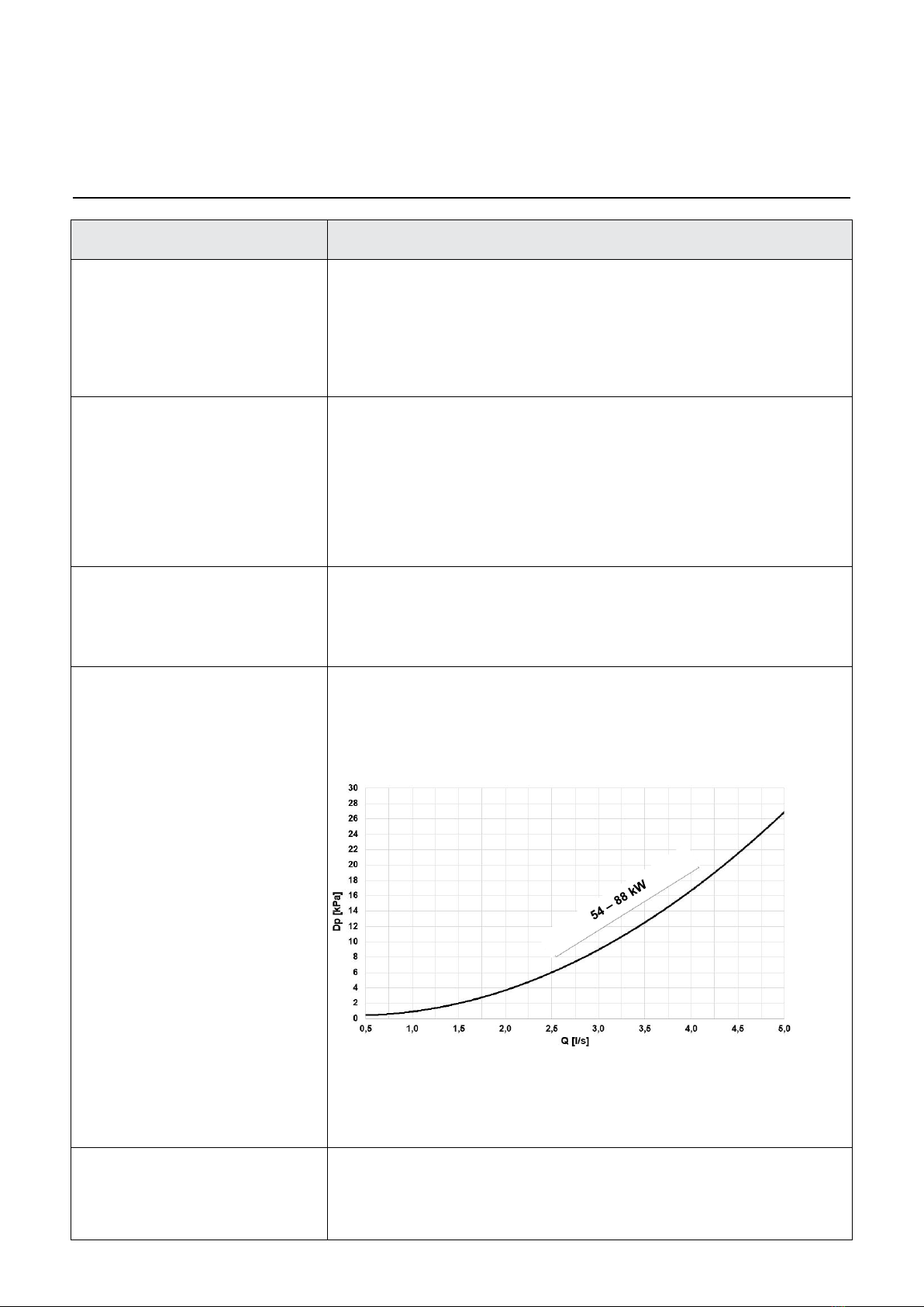
Internal exchanger
Direct expansion heat exchanger,
brazed AISI 316 stainless steel
plates, in pack without seals using
copper as the brazing material, with
low refrigerant charge and large
exchange surface.
The exchanger comes complete
with:
external thermal insulation no-
condensation, thickness 17 mm, in
expanded polypropylene (EPP)
antifreeze heater to protect the wa-
ter side exchanger, preventing the
formation of frost if the water tem-
perature falls below a set value.
flow switch
anti-ice probe
External exchanger
c coil exchanger made with copper
pipes placed on staggered rows me-
chanically expanded to better adhere
to the fin collar.
Fins are made from aluminum with
hydrophic treatment that allows the
correct evacuation of condensing wa-
ter and optimizes defrosting.
Fins have a special corrugated sur-
face and they are appropriately dis-
tanced to ensure the maximum heat
exchange efficiency. n.
Fan
Helical fans with 4 profiled blades
made of reinfoced plastic, directly
coupled to the DC brushless motor
with electronic control, IP 54 execu-
tion.
Fans are located in aerodynamically
shaped structures to increase efficien-
cy and minimize noise level, equipped
with accident prevention steel guards.
Refrigeration circuit
Refrigeration circuit with: Direct ex-
pansion heat exchanger
filter dryer
liquid receiver
pressure transducer (high/low)
refrigerant temperature probe
electronic expansion valves
non return valve4-way reverse-cycle
valve
high pressure safety pressure
switch
low pressure safety pressure switch
low pressure safety valve
return liquid separator
oil separator
Refrigeration circuit
cooling system of the of the electri-
cal control panel using undercooled
liquid
Only for range 65–88 kW:
economizer exchanger
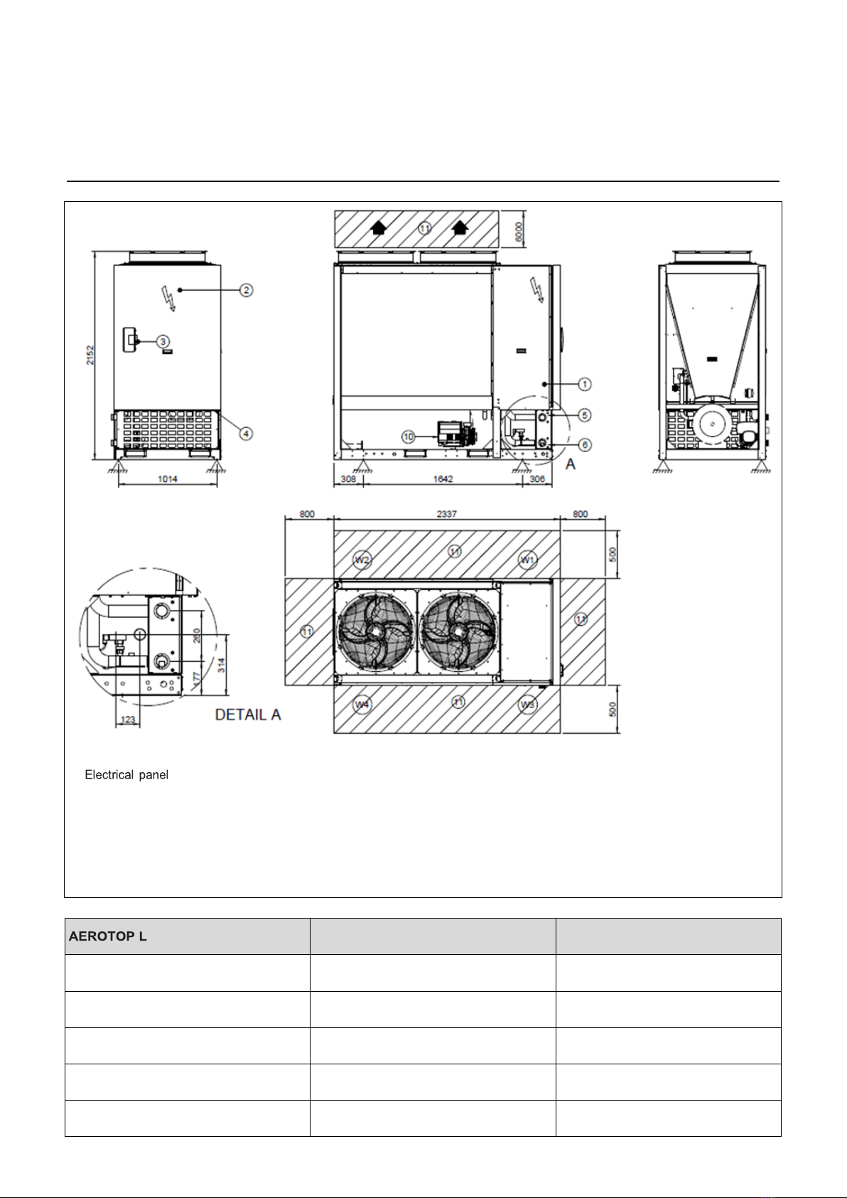
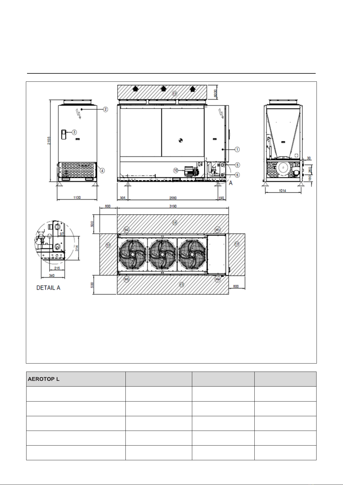
Electrical panel
main door lock isolator switch
phase monitor
auxiliary components protection fuse
compressor protection fuse
fan motor thermal protections
interface terminal with graphic dis-
play
intuitive graphical interface retro
lighted
display of operating status
Unit On/Off and overload reset
manual changing of the operating
mode (hot or cold)
management of the operating pa-
rameters
daily, weekly programmer of temper-
ature set-point and unit on/off
self-diagnosis system with immedi-
ate display of the fault code
compressor overload protection and
timer
relay for remote cumulative fault
signal
potential-free contact for remote on-
off control
potential-free contact for summer /
winter change
potential-free contacts for compres-
sor status
serial port with modbus port (RS485)
for remote communication
Test
Unit subjected to factory-tested in
specific steps and test pressure of the
piping of the refrigerant circuit (with
nitrogen and hydrogen), before ship-
ping them