19
Charging Geothermal Heating Systems
Charging with Antifreeze
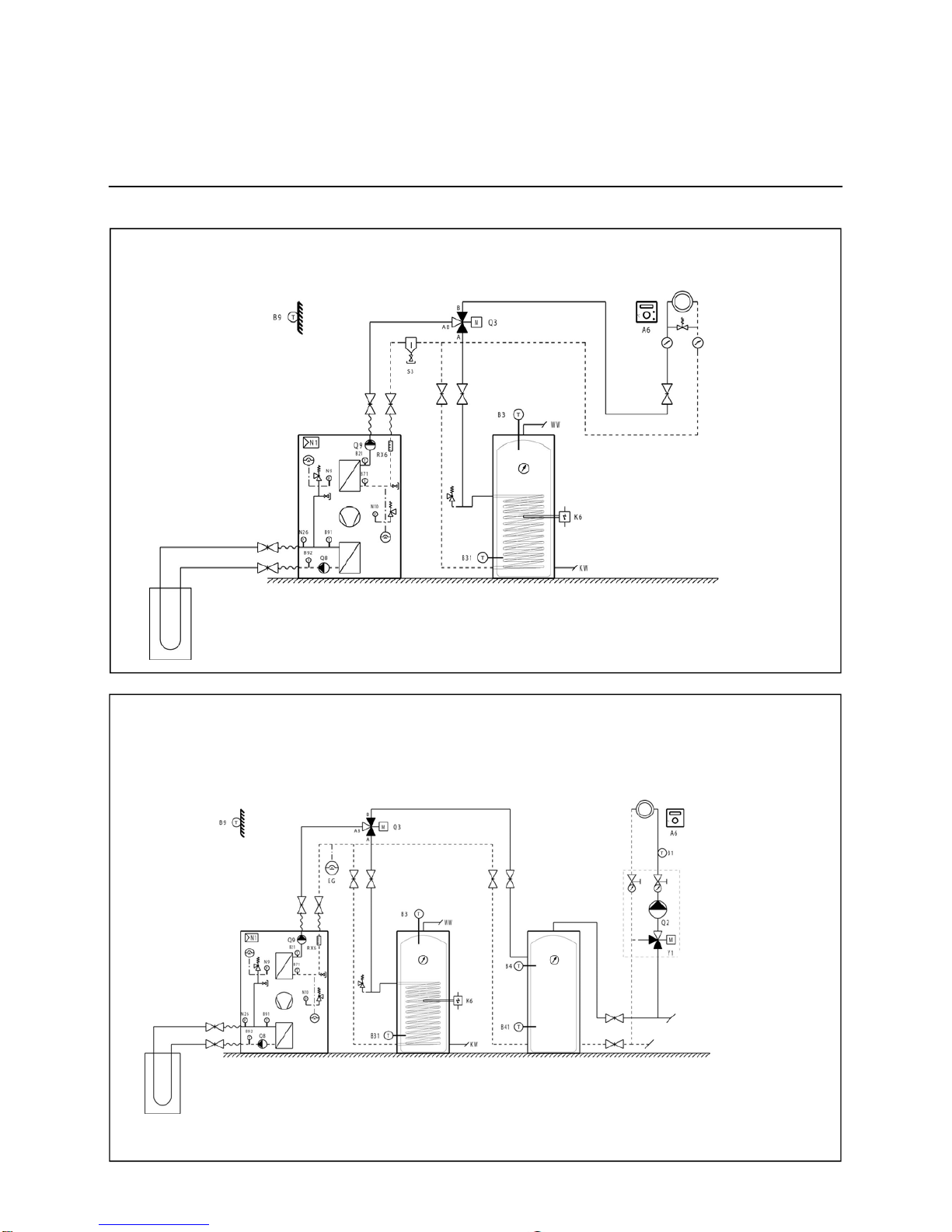
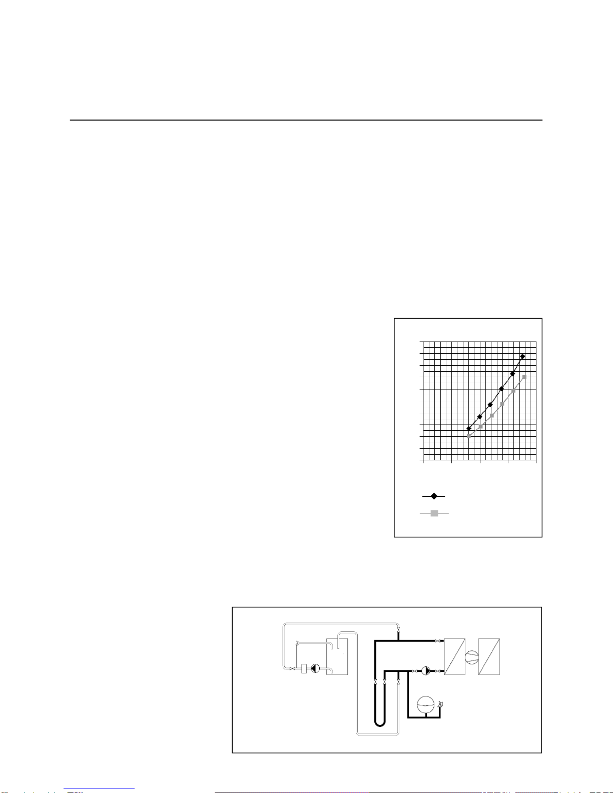
Correctly Charging a Geothermal Heating System Circuit
Charging with Antifreeze
After flushing, the entire geothermal
heating system circuit is to be filled
with clean tap water. Follow the steps
below to prepare the required con-
centration of antifreeze with a 100%
concentrate. For example:
The required antifreeze concentration
is 25% (ideal range is 25-30%) with a
140-m Duplex® ø 32 mm BHE.
(Content per meter = 4 pipes x 10 dm,
length x 0.13 dm,
inner radius2x rr = 2.12 l/m.)
Correctly Charging a Geothermal
Heating System in 14 Steps
1. Flush the GHS circuit as described
on page 18.
2. Calculate the probe volume acc. to
table above. One GHS (GHS
ø 32 mm) has 2.12 l/m content per
meter. This yields the following
GHS content for our example:
140 m x 2.12 l/m = 296.8 liters
(297 l). Do not forget the content of
the connection lines up to the heat
pump, 30 liters in our example.
This results in a total system content
of 297 liters + 30 liters = 327 liters.
3. Required volume of 100% anti-
freeze concentrate:
25% of 327 liters = 82 liters.
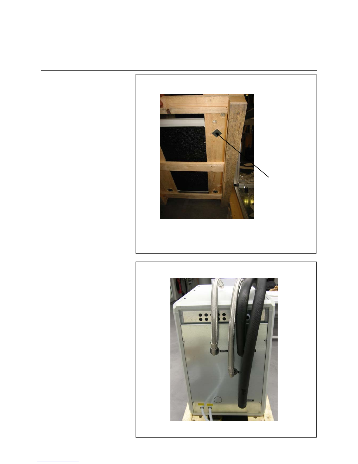
4. Close the sliders to the heat pump.
Remove the drain hose from the
tank and place in drain.
5. Open the sliders of the GHS – if
several probes have been
installed, one slider after the other
is opened during charging.
6. Fill the mixing tank with an approx.
mixture of 1:1 of antifreeze
concentrate and fresh water.
Depending on tank size, not all of
the 82 liters of concentrate fit into
the tank (see calculation, item 3).
7. Switch the feed pump on.
As soon as the tank begins to
empty, continuously fill in the
remaining antifreeze concentrate
and additional fresh water into the
mixing tank at a ratio of approx.
1:1. Make sure that always at least
40 liters of mixed reserve remains
in the tank. Volume markers can
be attached to the edge of the
tank to help you determine its
volume.
8. The feed pump is allowed to run
until the entire antifreeze
mixture – except for the 40 liters
reserve – are filled in and then is
switched off at once. Excess tap
water drains from the drain hose
into the drain.
9. Now insert the drain hose into the
tank, turn the feed pump back on,
and allow it to run until glycol and
water are thoroughly mixed. This
takes about 6-times to 8-times as
long as it takes for flushing (see
diagram, item flushing).
10. Close charging valves at drain
hose and then those at the
geothermal heating system
distributor. The excess pressure
valve (2.5 bar) routes the excess
mixture back into the tank. Shut off
feed pump. About 40 liters remain
in the tank. Some of the mixture
was absorbed by the expansion
of the geothermal heating system.
11. In case of relatively long geo-
thermal heating systems and
insufficiently mixed mixture, the
excess pressure valve at the tank
is triggered and thereby intensifies
mixing.
12. If several GHSs are combined into
one system, the second, third, etc.
GHS is first flushed and then
charged individually until all have
been processed.
13. Once all geothermal heating
systems are charged, the eva-
porator and the brine circulating
pump must be charged next.
All sliders to the geothermal
heating systems are closed for
this purpose and the sliders to the
evaporator are opened.
The remaining mixture is now
carefully pumped via the slider at
the filling hose. Allow water in the
circuit to escape via the drain
hose. As soon as the glycol
mixture emerges as the drain hose
(color change), close the corre-
sponding valve and allow the
pump pressure to charge the
expansion vessel (2.5 bar). Then
close the valve at the filling hose.
The system is now charged with
the correct concentration and
correct operating pressure without
introducing pollutants to the
system.
14. Now carry out a pressure test.
This test should be performed
over an extended period to avoid
the hassle of finding leaks later on.
Note: Antifreeze mixtures are
more likely to result in leaks earlier
than water alone!
Geothermal heating
system (probe)
diameter
Content per
meter
25 mm 1,31 l/m
32 mm 2,12 l/m
40 mm 3,34 l/m