manuals.online logo
Brands
  1. Home
  2. •
  3. Brands
  4. •
  5. elco
  6. •
  7. Heat Pump
  8. •
  9. elco AQUATOP T Series Technical manual

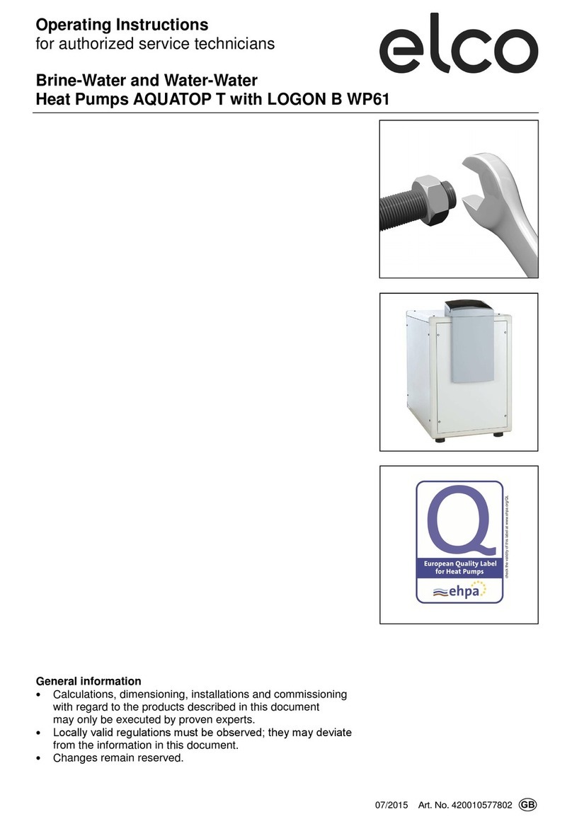
elco AQUATOP T Series Technical manual

Planning Document
Brine-Water and Water-Water
AQUATOP T Heat Pumps
General information
• Calculations, dimensioning, installations and commissioning
with regard to the products described in this document
may only be executed by proven experts.
• Locally valid regulations must be observed; they may deviate
from the information in this document.
• Changes remain reserved.
02/2013
A
rt
. No.
420010415301
2
Table of Contents
Table of Contents …………………………………………………....... 2
Planning Notes Overview............................................................ 4
Heat Output AQUATOP T at 35°C Flow............ 5
Heat Output AQUATOP T at 50ԨFlow............. 6
Heat Output AQUATOP T.. HT at 35°C Flow..... 7
Heat Output AQUATOP T.. HT at 60°C Flow….. 8
Heat Pumps, General Information...................... 9
Configuration of Pressure Expansion Vsels....... 11
AQUATOP TC Configuration
Integrated 12-l Expansion Vessel....................... 12
Determining Heat Output and Allowances......... 13
Basic Principles for Configuring
Geothermal Probes............................................ 14
Basic Principles for Configuring
Geothermal Tube Collectors…………………….. 15
Basic Principles for Configuring
Geothermal Probes............................................ 16
Brine-Water Heat Pumps................................... 17
Borehole Heat Exchanger System,
Basic Scheme.................................................... 18
Implementation Notes......................................... 18
Checklist............................................................. 19
Interfaces of Borehole Heat Exchanger Systems 19
Borehole Heat Exchanger Supply Trench.......... 20
Example of a Borehole Heat Exchanger............ 21
Water-Water Heat Pumps.................................. 22
Groundwater, Basic Scheme.............................. 23
Groundwater System......................................... 24
Cooling with Heat Pump Systems...................... 28
Unit Dimensions AQUATOP T..C................................................. 32
AQUATOP T17CH............................................. 33
AQUATOP T..H................................................. 34
AQUATOP T22-T44, THT, TR........................... 35
Technical Data AQUATOP T05C - T08C.................................... 36
AQUATOP T10C-T14C...................................... 38
AQUATOP T07CHT - T11CHT.......................... 40
AQUATOP T17CH............................................. 42
AQUATOP T22H-T43H...................................... 44
AQUATOP T05CX - T08CX............................... 46
AQUATOP T10CX - T12CX............................... 48
AQUATOP T06CR - T08CR............................... 50
AQUATOP T10CR - T14CR............................... 52
AQUATOP T05CRX - T08CRX.......................... 54
AQUATOP T10CRX - T12CRX.......................... 56
AQUATOP T17CHR........................................... 58
AQUATOP T22HR - T43HR............................... 60
Integrated Pumps
Compact Heat Pumps Reclamation Pump............................................. 62
Heat Pump......................................................... 64
Performance Data Brine-Water AQUATOP T..C.............................. 65
Water-Water AQUATOP T..C............................. 66
Brine-Water AQUATOP T..H............................. 67
Water-Water AQUATOP T..H............................. 68
Brine-Water AQUATOP T..HT........................... 69
Water-Water AQUATOP T..HT.......................... 70
AQUATOP T..R.................................................. 71
AQUATOP T..HR............................................... 73
Operating range................................................. 75
Performance charts………………………………. 76
3
Table of Contents
Hydraulic System Standard Scheme, Overview.......................... 88
AQUATOP TC 1........................................... 89
AQUATOP TC 1-6........................................ 90
AQUATOP TC 1-I......................................... 91
AQUATOP TC 2-I......................................... 92
AQUATOP TC 1-6-I...................................... 93
AQUATOP TC 2-6-I...................................... 94
AQUATOP TC 2-6-H.................................... 95
AQUATOP TC 2-6-7-H................................. 96
AQUATOP TC 1-6-7.................................... 97
AQUATOP T 1-I........................................... 98
AQUATOP T 2-I............................................ 99
AQUATOP T 2-5-B-I..................................... 100
AQUATOP TC Expansion Scheme BL......... 101
AQUATOP T Expansion Scheme BL........... 101
Additional Schemas AQUATOP TC 2........................................... 102
AQUATOP T 2.............................................. 102
Additional Hydraulic Suggestions AQUATOP TC Expansion Scheme M.......... 103
AQUATOP T Expansion Scheme M............. 103
AQUATOP T Cascade with
PWH Isolating Circuit................................... 104
AQUATOP TR with Active Cooling.............. 106
Heat Pump Controller
LOGON B WP ..................................................................... 108
Notes ..................................................................... 109
The high quality brine-water and
water-water heat pump AQUATOP T
extracts geothermal heat from the
environment and releases it
to the heating system at a higher
temperature.
The reversible model of the
AQUATOP T heat pump series can
also be used for active cooling.
The broad range of AQUATOP T heat
pumps is available in the following
versions and models:
AQUATOP T…C
The compact heat pump with inte-
grated circulation pump, expansion
vessel and integrated electrical
heater element, 3x400VAC
AQUATOP T..HT
In high temperature version for flow
temperature Up to max. 65 C
3x400VAC
AQUATOP T..H
In high temperature version for flow
temperature Up to max. 60 C
3x400VAC
AQUATOP T..X
Version for 1x230 V
(available in F / I / B).
AEROTOP T..R
Reversible heat pumps used to heat
and cool.
Product Overview
AQUATOP T
4
0.0
5.0
10.0
15.0
20.0
25.0
‐50 51015
Potenzatermica(kW)
Te mp e r a t u r a sorgentefredda(°C)
5
Planning Notes
Overview
Heating output AQUATOP T with 35°C Flow
Heat output curves also apply to same models in reversible (R), and
mono-phase (M) designs.
AQUATOP T14C
AQUATOP T12C
AQUATOP T10C
AQUATOP T08C
AQUATOP T06C
AQUATOP T05C
Heating capacity (kW)
Heat source temperature (°C)
0.0
5.0
10.0
15.0
20.0
25.0
‐50 51015
Potenzatermica(kW)
Temperaturasorgentefredda(°C
6
Planning Notes
Overview
Heating output AQUATOP T with 50°C Flow
AQUATOP T14C
AQUATOP T12C
AQUATOP T10C
AQUATOP T08C
AQUATOP T06C
AQUATOP T05C
Heating capacity (kW)
Heat source temperature (°C)
Heat output curves also apply to same models in reversible (R), and
mono-phase (M) designs.
7
Planning Notes
Overview
Heating output AQUATOP T..H and T..CHT with 35°C Flow
Heating capacity (kW)
Heat source temperature (°C)
AQUATOP T43H
AQUATOP T35H
AQUATOP T28H
AQUATOP T22H
AQUATOP T17CH
AQUATOP T11CHT
AQUATOP T07CHT
Heat output curves also apply to same models in reversible (R) design.
8
Planning Notes
Overview
Heating output AQUATOP T..H and T..CHT with 60°C Flow
Heating capacity (kW)
Heat source temperature (°C)
AQUATOP T43H
AQUATOP T35H
AQUATOP T28H
AQUATOP T22H
AQUATOP T17CH
AQUATOP T11CHT
AQUATOP T07CHT
Heat output curves also apply to same models in reversible (R) design.
9
Planning Notes
Heat Pumps, General Information
Planning and installation must be
carried out in compliance with the
relevant rules and regulations (SWKI,
SIA, AWP, VDI 4640, etc.).
Prior Clarifications / Approvals
It is recommended to clarify the
following items early on in the planning
phase:
With electric company:
- Connection permit
- Starting current
- High/low/special rates
- Blocked times
Heat sources:
Water extraction from public waters
and the positioning/repositioning of a
geothermal probe or tube collector
must be approved by the respectively
responsible local office or authority.
This is usually the Office of Energy
and Water Management or Environ-
mental Protection Agency (indicate
coordinate of house location).
Heat Pump Dimensioning
Compared with other heat generators,
the heat pump has a smaller applica-
tion scope. The heat output and the
required power and with that the utili-
zation ratio of the heat pump vary
depending on heat source and heat
utilization temperatures.
A basic principles applicable here
states that the smaller the difference
between heat utilization and heat
source temperature the more efficient
(better performance number) the
system can be operated. This is why
the planner/installer of the heat pump
must take boundary conditions into
account.
The system must be configured and
dimensioned in such a way that usage
limits are not exceeded.
Water Heating
In addition to heating rooms, a heat
pump can also be used to heat water.
This makes sense since the energy
savings are considerable compared
with electrical water heaters.
Depending on the refrigerant used,
different max. hot water temperatures
are reached (50°C - 60°C). These are
the result from the operating limits of the
refrigerant as well as the structure of
the cooling circuit of the heat pump.
Water is heated indirectly with the
following typical solutions:
- Coil storage tank
- Combination storage tank (heat
storage with integrated boiler) or
Spira storage
- Storage with external plate
exchanger (Magro system)
When selecting coil or external plate
storage tanks, it is especially important
to make sure the heat exchanger
surface is sufficient. This requires taking
water volume, temperature differences,
as well as heat pump capacity into
consideration. A combination with solar
collectors is quite possible. using a
suitable water heat, e.g. a combination
storage tank, it is possible to heat water
entirely with solar collectors, especially
during the summer.
Buffer Storage
Always make sure the entire output of
the heat pump is always accepted
regardless of the type of storage installa-
tion.
Integrating a technical storage or
heat storage tank is generally recom-
mended.
It ensures optimal operating
conditions such as the following:
• Output excesses of the heat pump
are absorbed
• Bridging EC off periods
• Enables several heating circuit
Connections
Buffer storage tank should be omitted
only in the following cases:
• If the heating water volume is
greater than 25 liters per kW
heating output or with a good
storage capability of the heat
emission system (floor heater
configured < 40 °C)
• No thermostatic valves
t = V * c * ∆t
Qh * 60
V = Tank volume in liters
Qh = Heat demand in watt
t = Bridging time in minutes
c = 4187 W/s
∆t = Temp. difference, heating circuit
Circulating Pumps
The evaporator and condenser flow
volume specified by the heat pump
(HP) must be adhered to consistently
to configure and dimension the
circulating pumps. Speed-controlled
circulating pumps may not used for
the thermal emission of the HP.
The heat source pumps (brine/
groundwater) must be suitable for use
with cold water. The viscosity of the
heat carrier medium must be consid
ered when configuring the system.
Overflow Valve
In case of heating systems with
variable or hot water flows that can be
shut off (e.g. thermostatic valves) and
serially installed storage tank, an over-
flow valve must be integrated
upstream of the circulating pump.
This ensures the min. flow of heated
water and prevents frequent switching,
which may lead to malfunctions.
The overflow valve must be set and
dimensioned properly.
The size of the buffer storage depends
on the max. heat output and the max.
permissible activation frequency of the
heat pump.
A general reference value is approx.
30 lto 50 liters per kW heat output.
For an increased buffering also more.
For the coverage time (without
considering the internal storage
capacity of the heating system) of the
heat demand using a buffer storage,
e.g. in case of an EC off period or
outage, can be calculated as follows:
10
Planning Notes
Heat Pumps, General Information
Transport
Never tilt the heat pump beyond max.
30º (in any direction) when trans-
porting it. Avoid exposing the heat
pump to any type or degree of mois-
ture or humidity.
Protect the heat pump from damage
during all construction phases.
Setup
The heat pumps can be set up on a
smooth, level, and plane surface with-
out the need of a base or pedestal.
The installation room must be dry and
frost-free. Rooms with much humidity
such as laundry rooms, etc. are not
very suitable for installing the heat
pump. The min. clearances must be
adhered with for all equipment to
ensure access in case of maintenance
and control tasks.
The heat pumps should never be set
up on a floating floor.
Heater Room Ventilation
Due to the low heat emission of the
heat pump, the heater room remains
practically unheated. To prevent high
levels of humidity in the room that
may damage the equipment, install a
non-closable vent of at least 100 cm2.
Noise Emissions
Equipment-borne noise transferred
to the heating system, electrical cable,
and the building can be avoided by
using flexible connections throughout:
• Tubes/hoses for pipe and duct
connections
• Flexible electr. connections
• With wall openings, avoid direct
contact of pipes and ducts with
walls
• Anti-vibration fasteners
For the choice and the planning of the
site the noise impact on the surround-
ing environment must be considered.
Therefore it is necessary to respect
the local directives on the acoustic
protection. In case of doubt it is neces-
sary to turn to the consultation of an
acoustic technician.
AQUATOP T heat pumps run
extremely quiet, thanks to the noise—
dampening insulation of the cladding
as well as the multi-dampened support
of the cooling circuit.
Hydraulic Integration
We offer different hydraulic standard
schemes for each heat pump. Integra-
tion based on these variants ensures
trouble-free and secure operation.
Before connecting the heat pump, the
entire piping of the system of new and
old equipment alike must be thoroughly
flushed. Residues left in the heating
pipes, ducts, or the borehole heat
exchangers / geothermal tube collec-
tors may cause damage to the
heat exchangers and HP malfunctions.
We recommend using a dirt trap in the
heat return.
The fill-up water of the heat system
must be treated according to the re-
gulations of the professional associa-
tions.
A complete ventilation is important
since Otherwise the correct operation
of the heat pump is affected.
Accordingly an exhauster must be
used. With compact heat pumps an
exhauster is installed on the flow.
Electrical Connection
Fuses must be used with the heat
pumps in accordance of the enclosed
connection diagram and connected to
the definite house connection line
(no disruptions of electrical supply due
to construction work, phase change).
Do not carry out a trial run after
completing the wiring work.
The heat pump is to be protected
electrically from startup by unaut-
horized persons.
Electrical connection work must be
carried out by a licenses technical
expert.
Initial Startup
The initial startup must be carried out
by qualified technicians or the warranty
will become void.
The installed heat pump should not be
started until all steps of the installation
process have been completed.
The technician in charge of the initial
startup (commissioning) is not an installer
or planner and can only complete
his or her job successfully if all system
parts are complete and all planning
values needed to configure the system
are available.
Initial startups are carried out only on
heat pumps that are:
• completely filled on the water side
and vented (heat source, heater)
• equipped with a definite electrical
connection line
• and in the presence of the by an
electrician or heating system installer
• completely wired (sensors, drives
etc.) according to the designated
system scheme.
Since an overload may cause severe
damages to the heat pump as well as
the heat source system, operating the
pump under the following conditions is
prohibited:
- Construction drying
- System/unit used in unfinished
buildings
- Windows or exterior doors not
yet lockable or still uninstalled.
In this case a temporary construction
heating should be used.
If the conditions listed above are not
met, the initial startup cannot be carried
out. We reserve the right to invoice the
associated costs.
The warranty for heat pump damages
becomes null and void in case of
noncompliance with these planning
notes or the corresponding operating
and assembly instructions.
11
Planning Notes
Configuration of Pressure Expansion Vessels
VN = VA * F * X
Key:
Vn = Expansion volume
VA = System content acc. to
list below
F = Temperature-dependent
Factor
TZ = Average system temperature TZ = (TV + TR)/2 40°C 50°C 60°C 80°C
= F 0,0079 0,0121 0,0171 0,029
X = Safety factor
up to 30 kW X = 3,0
31 - 150 kW X = 2,0
above 150 kW X = 1,5
Safety factor for boiler output
Important:
Water contents of hot water tanks
(buffer storage) are not considered in
the table and must be added
separately.
Type
0,5 bar 0,8 bar 1,0 bar 1,2 bar 1,5 bar 1,8 bar
PND 18 10,3 8,7 7,7 6,6 5,1 3,5
PND 25 14,3 12,0 10,7 9,1 7,1 4,7
PND 35 20,2 17,0 15,0 13,0 10,0 7,0
PND 50 28,6 24,4 21,4 18,5 14,3 9,8
PND 80 45,7 38,6 34,3 29,7 22,9 16,5
max. height Hp 2 m 5 m 7 m 9 m 12 m 15 m
Initial Pressure in Empty Vessel (= Hp + 0,3 bar)
Boiler Output (kW)
VA System Volume (l)
1 = Floor heating
2 = Radiators
3 = Heating panels
Select the expansion vessel based on
the expansion volume and the system
height Hp. The system height Hp is the
height from the middle of the
expansion vessel up to the upper
point of the heating unit.
12
Planning Notes
AQUATOP T..C Configuration
Integrated 12-l Expansion Vessel
General Information about the
Correct Configuration
AQUATOP T..C heat pumps can be
installed without an additional external
expansion vessel if all of the following
conditions are complied with:
- Direct heating circuit:
Standard 1 or Standard 1-6
- H (system height) <= 7 m
- Heating capacity at outside
temp. (Ta) of max. 14 kW
- Water volume of system VA
may
not exceed the
values listed in
the table.
Installation Example
AQUATOP T14C, Standard 1-6,
dimensioning conditions of the system:
- TZ 35°C: max. averaged temp.
of the system at heating operation
(corresponds with 40°C/30°C)
- H (system height) <= 7 m
- Ta (outside temperature
dimensioning): -10°C
- AEROTOP T14C max. capacity
at outside temp. of -10°C and
40°C flow temperature:
14.1 kW (limits)
- Condition: V
A
<= 290 l; rough
verification: 14.1 kW installied
capacity x 20 l/kW with floor heater
= 282 l < 290 l: OK!
V
A
must be known for a conclusive
dimensioning of the expansion
vessels.
Permissible Water Volume V
A
of the
System
The following table lists the max.
system water volumes in dependence
of TZ (max. averaged temperature of
system while in heating operation and
the static system height (H), which can
absorb the expansion of the integrated
12-l expansion vessels.
VA[liter]
H (m) p0(bar) TZ = 30°C TZ = 35°C TZ = 40°C TZ = 45°C TZ = 50°C TZ = 55°C TZ = 60°C
2 0.5 550 390 300 230 190 160 130
3 0.6 520 370 280 220 180 150 130
5 0.8 460 330 250 190 160 130 110
6 0.9 430 310 230 180 150 120 100
7 1 400 290 210 170 140 110 100
9 1.2 340 250 180 140 110 100 -
12 1.5 240 180 130 - - - -
15 1.8 - - - - - - -
H System height
po (bar) Min. expansion vessel pre-pressure
TZ Max. averaged operating temperature of the system (Tvl + Trl)/2 during heating operation
PSV Switching on point of the overpressure valve = 3 bar
VAPermissible water volume VA of the system.
Heating system water volume incl. 50 l of the integrated buffer storage tank.
13
Planning Notes
Determining Heat Output and Allowances
Retrofitting an existing oil or gas
heater with heat pump:
The heating capacity can be calculated
based on the existing average fuel
consumption.
Example:
Number of people 4
Hot water demand 50 liters
per person and day.
Heat demand allowance:
Q˙WW = 4 x 0,085 kW = 0,34 kW
New construction:
The heat demand is calculated in accordance with national and local standards.
24 h
f =
24 h - Sperrzeit pro Tag (h)
Hot water demand
per person and day (l)
Additional heating output
per person (kW)
Tw = 45° C
∆T = 35 K
30 0,051
40 0,068
50 0,085
60 0,102
Allowances to the Heat Pump Output
Off Periods (Blocked Times)
The off periods (blocked times) theo-
retically should be considered by the
following formula and the heat demand
should be multiplied with the factor f.
Note:
The above made calculations are a
Rough estimate. Please advise the
heating planner for exact calcula-
tions.
With hot water Without hot water
Mid-level
altitude
Qh = Oil consumption (Ltr.)
300
Qh = Oil consumption (Ltr.)
265
In excess of
800 m above
sea level
Qh = Oil consumption (Ltr.)
330
Qh = Oil consumption (Ltr.)
295
Oil heater
With hot water Without hot water
Mid-level
altitude
Qh = Gas consumption (m3) x 0.93
300
Qh = Gas consumption (m3) x 0.93
265
In excess of
800 m above
sea level
Qh = Gas consumption (m3) x 0.93
330
Qh = Gas consumption (m3) x 0.93
295
Gas Heater
Qh = Heat demand in kW
14
Planning Notes
Basic Principles for Configuring Geothermal Probes
Basic Principles for Operating
Geothermal Probes
The possible load of a geothermal probe
depends primarily on the subsoil/rock
and the borehole depth. Some deep
borehole heat exchangers yield a better
annual performance factor of the heat
pump system than some less deep
borehole heat exchangers with the same
total length. The geographic region of
the building's location must be consid-
ered as well.
If properly configured and implemented,
a geothermal probe can have a service
life of up to 100 years.
Output and load of geothermal probes
The following specific dimensioning
values have proven to be effective for
smaller systems up to approx. 4 to 6
"not encapsulated" probes:
(normal subsoil; cf. VDI 4640)
- 100 kWh/m/year max. heat extraction
- 50 kWh/m/year max. specific probe
extraction capacity
Larger probe fields must be checked
with a simulation calculation for correct
dimensioning.
Effect of Depth and Diameter
Borehole heat exchangers positioned
lower permit a higher specific output
while maintaining the same median
source temperature or a higher median
source temperature while maintaining
the same total length.
The soil or rock temperature increases
by approx. 1°C every 30 m of depth.
Deep borehole heat exchangers,
however, have a higher flow resistance.
Optimization thus must be achieved
based on the type of system used
(number of probes, heat source
temperature, performance rate of heat
pump, brine pump coefficient).
Basic Principles for Configuring
Geothermal Probes
Local Norms and regulations must
always be considered and have priority
like the for Switzerland valid SIA 384-6
The collector lengths indicated in the
documentation affect the following
basic principles:
The indicated lengths refer to the
following basic principles:
- Monovalent operation
- Extraction capacity 45W/m
- Approx. 1800 hrs/year (max.
2000 operating hours/year)
- Annual extraction energy approx.
90 kWh/m/year (max. 100 kWh/ m/
year)
- Mid-level altitude up to approx.
800 m above sea level
The collector lengths are to be adjusted
in case of the following system
conditions:
- Bivalent operation (extracted
energy max. 100 kWh/m/year)
- Higher operating hours (>2000),
e.g. in mountainous regions
- High hot water demand
(Sum of extracted energy max.
100 kWh/m/year)
- Pool water treatment
15
Planning Notes
Basic Principles for Configuring Geothermal
Tube Collectors
Description of Geothermal Tube
Collectors
Contrary to borehole heat exchangers,
tube collectors are installed vertically
at a depth of approx. 1.0 – 1.5 m.
Continuous pipes with a diameter of
20 to 40 mm are used for the tube
collectors. These pipes are installed in
the soil or rock horizontally and tubular-
shaped at a distance of 0.6 to 0.8 m.
Polyethylene pipes are a preferred
material. This material has the neces-
sary elasticity and favorable flow
characteristics as well as low friction
losses. For this type of utilization, they
are corrosion-proof and nearly
indestructible. They have a service life
of approx. 50 years.
Max. Extraction Capacity of
Geothermal Tube Collector Systems
The following soil or rock properties
are especially important for the proper
dimensioning of the installation area:
• k-factor/thermal conductivity
(W/mK)
• •Specific heat (kJ/kgK)
• Density (kg/m3)
These three parameters are primarily
affected by the humidity content of the
soil or rock. Normally, the soil can be
expected to be moist. Practical applica-
tion requires only the following
differentiation:
Humidity content of soil:
• Wet
• Moist
• Dry
The wetter the soil, the better the heat
transfer ratios.
Soil consistency:
• Sandy
• Loamy
• Rocky
Global sunlight levels:
• Sunny
• Normal
• Shady
Humidity content, soil consistency, and
sunlight levels are to be weighted
according to their direct effect.
In Central Europe, the following
constellation usually applies:
Moist/sandy/normal
The following max. extraction capacities
can be assumed based on this constel-
lation and collected experience:
15 - 20 W/m2
If the weighting of the influencing factors
uncovers a constellation with values
below the normal ones, the heat ex-
traction per m2of soil area must be
reduced. In case of unfavorable condi-
tions, e.g. stony-dry-shady, the following
value is surely all that can be expected:
10 - 15 W/m2
If the soil can be characterized as moist
and loamy, the following value can be
expected:
20 - 25 W/m2
Basic Principles for Configuring
Geothermal Tube Collectors
The collector lengths indicated in the
documentation affect the following basic
principles:
The indicated lengths refer to the
following basic principles:
- Monovalent operation only for room
heater
- Extraction capacity 20W/m2
- Approx. 1800 hrs/year (max. 2000
operating hours/year)
- Annual extraction energy approx.
40 kWh/m/year (max. 50 kWh/ m/
year)
- Mid-level altitude up to approx.
800 m above sea level
The collector lengths are to be adjusted
in case of the following system
conditions:
- Bivalent operation (extracted
energy max. 50 kWh/m/year)
- Higher operating hours (>2000),
e.g. in mountainous regions
- Water heating (sum of extraction
energy max. 50 kWh/m/year)
chapter)
Pool water preparation, longer
operating hours, bivalent systems
We recommend not to configure these
types of systems with tube collectors
since the soil or rock cannot be deter-
mined with certainty, which poses the
risk of an overload of the ground.
Please consult leaflet No. 43 of the
BDH from May 2010 for additional
information.
16
Planning Notes
Basic Principles for Configuring Geothermal Probes
Thermal Insulation
All lines, pumps, and valves must be
equipped with cold insulation material
as a protective seal from vapor
diffusion (install drip pan, if necessary).
Connection Lines and Distributors
- Select the shortest line distance
possible
- Dig trench for connection lines
down to frost penetration layer, if
possible with a slight incline
towards the borehole heat
exchanger
- Make sure the brine trench allows
water to penetrate through, fill with
sand, dewater if needed
- Embed connection pipes in sand
layer (risk of damage)
- Do not cover until a pressure test
has been conducted
- Fill system according to the
Technical Datasheet AWP
Exterior Installation
- Make sure distributor is accessible
- Seal wall openings and heat
insulation to protect from water
Interior Installation
- Install drip pans if needed
- Avoid equipment-borne noise
Transference
Heat Source Booster Pump
Because the median temperature
difference, the flow rate, and the
material properties of the used heat
carrier fluid (water-antifreeze mixture)
also play a decisive role, the di-
mensioning of the heat source booster
pump must also be carried out very
carefully. In addition, the annual per-
formance factor of the system can be
affected significantly due to the high
perceptual share of the electrical input
of the heat source booster pump,
especially with smaller systems.
The brine circuit of the borehole heat
exchanger must be calculated carefully
concerning the flow volume and pres-
sure losses.
The line installation and dimensioning
as well as the probe lengths and
number must be optimized in reference
to the system.
Only then is it possible to determine the
right heat source booster pump for the
system. The large difference of the
hydraulic coefficient must also be
included in the dimensioning process
for the booster pumps available in
many different sizes.
The integrated brine pump of compact
heat pumps must be checked to ensure
it is suitable for the application at hand.
17
Planning Notes
Brine-Water Heat Pumps
Application Range
Brine-water heat pumps are usually
used as monovalent heaters.
If the heat pump and the borehole heat
exchanger have been dimensioned
correctly, geothermal energy provides
a relative constant heat source with a
good performance rating.
Monovalent Operation
If the heat pump is used in a monova-
lent manner (without auxiliary heater),
the following basic data must be
carefully determined and calculated:
• Determine heat capacity demand
acc. to local standards (SIA 384/2,
DIN 8900-6, DIN 8901) or deter-
mine based on the previous
energy consumption.
• Max. required flow temperature of
heating system.
The heat pump must deliver 100% of
the required average building capacity
at the lowest exterior temperatures and
max. flow temperatures.
Bivalent Operation
If the heat pump is used in a bivalent
manner (with auxiliary heater), the
following data must be carefully
determined and calculated:
• Determine heat capacity demand
acc. to local standards (SIA 384/2,
DIN 8900-6, DIN 8901) or deter-
mine based on the previous
energy consumption.
• Max. required flow temperature of
heating system.
• Determine the bivalent point
(switchover point).
The auxiliary heater is usually
dimensioned for 100% capacity.
When used in a bivalent-parallel
operating mode, the borehole heat
exchangers must be dimensioned by
an accredited engineering office.
Permits
A permit for the utilization of geothermal
energy must be obtained from the
locally responsible office or authority.
Each connection of an electric
heat pump requires a permit of the
responsible electric company or utility.
The electrical heat pump data must be
known for the application.
Borehole Heat Exchanger
The annual performance factor of a
heat pump (HP) is affected by the
configuration and dimensioning of the
borehole heat exchanger (BHE).
Dimensioning requires taking into
account the cooling capacity of the HP
at the configuration point, the service
duration per year, the geology, the
position, layout, and depth of the BHE.
The standard reference points is as
follows: cooling capacity at B0 /W35
(brine inlet temp. = 0°C,
flow temp. = 35°C) is assumed.
The general borehole and installation
conditions of the drilling company must
be observed when positioning geother-
mal probes.
For further information see chapter
‘Basic Principles for Configuring
Geothermal Probes’.
Thermal Recovery Time of the Soil
The annual heat pump operation
should not exceed 1800 hours per
year. If the number of operating hours
is higher, the borehole heat exchanger
must be dimensioned larger.
If service water is heated year-round,
the, borehole heat exchanger length
must be increased according to the hot
water demand so that a sufficient
amount of energy is replenished from
the surrounding soil or rock to the BHE.
This applies especially with well insu-
lated buildings (low energy) where
hot water heating takes up a large
share of the annual energy demand.
Brine Heat Carrier
The brine circuit requires the use of
non-polluting antifreeze agents (e.g.
Antifrogen N).
Compliance with the concentration of
20 - 30 vol. % is required and must be
checked periodically. The borehole
heat exchanger must be filled according
to the operating instructions. If anti-
freeze is added to a system subse-
quently, it cannot be guaranteed that
antifreeze and water are mixed properly.
Flush the pipe system before filling in
the heat carrier fluid. Never use air to
blow out the BHE. It must be filled with
fluid at all times. Pollutants may cause
decomposition of the heat carrier media.
This results in sludge, or the pollutant
itself may damage the heat exchanger
(malfunctions) and other components.
Connection Lines
Heat Source
The material compatibility of the lines
with the antifreeze agents must be
checked (no galvanized lines).
Connection lines must be kept as short
as possible. Condensation forms on
lines and fittings in warm rooms.
This must be prevented with vapor proof
insulation material or collected with a
drip tray. The installation must be
protected from corrosion (material
selection).
To be able to detect leaks, a pressure
controller must be installed in the brine
circuit for monitoring. It must be possible
to shut off each borehole heat exchanger
individually from the point of the distri-
butor.
Implementation of the Borehole Heat
Exchanger System
See separate basic scheme.
Equipment Setup
Installation location according to the
general planning notes, min. distances
and clearances see equipment
dimensions.
18
Planning Notes
Borehole Heat Exchanger System,
Basic Scheme and Implementation Notes
Borehole Heat Exchanger
• Accessibility and available space
for heavy equipment (pneumatic
vehicles) must be clarified.
• Pay attention to existing utility
lines
• Measure and mark drill position.
• Obtain geological expert opinion
or assessment as outlined by
drilling permit.
• Establish water and electrical
connection.
• Obtain liability/well insurance.
• Provide sludge trough.
Connection Lines and Distributors
• Select the shortest line distance
possible.
• Dig trench /approx. 80 cm) for
connection lines down to frost
penetration layer, if possible with
a slight incline towards the
borehole heat exchanger.
• Make sure the brine trench allows
water to penetrate through, fill with
sand.
• Embed lines in sand layer (risk of
injury).
• Do not backfill/cover until a
pressure test has been
performed.
Exterior Installation
• Make sure distributor is accessible.
• Seal and insulate wall openings
against water.
Interior Installation
• Equip all lines, pumps, and valves,
use protective vapor diffusion
insulation if needed
• Install drip pans if needed.
• Avoid solid-borne noise trans-
mission.
Thermal Insulation
• Sealed against vapor-diffusion.
• Provide sufficient wall thickness.
On-Site Tasks
• Coordination and implementation
of the line trenches, wall openings,
and well shafts.
• Filling in of the trench and closing
the wall openings after the install-
lation work.
Connections
Connection lines and distributors.
With more probes adjusting devices
are compulsory on site.
Additionally the length and the diameter
of the single probes must be labelled on
the distributor. With more probe fields
an additional adjusting device must be
available per distributor.
The adjustment of the probes and the
probe fields must take place on site.
Delivery/installation
by ELCO/ installation company
On-site
Ditches and openings
Recommendation: 5% of probe depth
Heat pump connection
Heat source booster pump and
safety equipment, connecton lines,
insulation, heat transfer medium
charge
Delivery/installation
by ELCO/ installation company
Sondentiefe
Integrated with
compact units
7
6
1 2 4 5
6
3
1 Shut-off slide
2 Pressure controller
3 Manometer
4 Expansion vessel
5 Safety valve
6 Feed and empty faucets
7 Manual exhauster
8 Adjusting device (STAD,
Taco-Setter) per probe and
probe field
Borehole Heat Exchanger
Borehole heat exchanger
boreholes, installation, and backfill
Delivery/installation
by ELCO/ drilling company
On-site
sludge pit
8
19
Planning Notes
Checklist
Interfaces of Borehole Heat Exchanger Systems
Interfaces with other technical partners
must be ensured when implementing a
brine-water heat pump. The enclosed
checklist is to facilitate this task.
Interface Item to be Clarified Result of Clarification
Authorities (Environmental
Protection Agency, District
Admin Offices)
First find out if drilling is possible or asses-
sment of permits required. In Switzerland, a
phone call to the Environmental Protection
Agency is sufficient, provide coordinates of
the borehole location (from TwixTel). Fill out
application after receiving the order for
drilling.
Electric company / utility Determine connection fees.
Find out whether installation of heat pump is
accepted.
Energy agencies, organizations Inquire about subsidies.
Drilling company Reserve drilling company time early.
Find out about insurance requirements/
aspects.
Geologist Geological expert opinion or assessment.
Mason / construction company Excavate trench for connection lines, in case
of retrofitting also core drilling for connection
line if needed.
Electrician Forward electrical scheme, establish con-
nection line. Pointing out correct connection
of the revolving field.
Landscaper Notify contractor of necessary landscaping
work, especially when retrofitting.
Initial startup by ELCO Coordinate appointment with electrical
installer. Before initial startup, make sure
the water flow volumes on brine and heater
side meet specifications.
20
Planning Notes
Borehole Heat Exchanger Supply Trench
Layout of Several Borehole Heat Exchangers
Borehole Heat Exchanger Supply Line Trench
Ditch/trench
Supply line
Detail of Supply Line Trench
incorrect
correct
Sand
Layout of Several Borehole Heat Exchangers (BHE)
correct incorrect
2 BHWs
3 BHEs
4 or more BHEs
7 or more BHEs
The above mentioned values are reference values
which must not be gone below.
Bigger probe fields must be dimensioned by a
geologist or a designated planner.

Other manuals for AQUATOP T Series

1

This manual suits for next models

33

Other elco Heat Pump manuals

elco AEROTOP T User manual

elco

elco AEROTOP T User manual

elco Aquatop TC Series User manual

elco

elco Aquatop TC Series User manual

elco AEROPUR User manual

elco

elco AEROPUR User manual

elco AEROTOP G User manual

elco

elco AEROTOP G User manual

elco AEROTOP L 054 User manual

elco

elco AEROTOP L 054 User manual

elco Trigon XXL EVO 600 Specification sheet

elco

elco Trigon XXL EVO 600 Specification sheet

elco AQUATOP T Series User manual

elco

elco AQUATOP T Series User manual

elco VARION C-POWER 20.0 User manual

elco

elco VARION C-POWER 20.0 User manual

elco AEROTOP L User manual

elco

elco AEROTOP L User manual

elco AEROTOP T Series Technical manual

elco

elco AEROTOP T Series Technical manual

Popular Heat Pump manuals by other brands

Nibe AG-AC10-65 Installer manual

Nibe

Nibe AG-AC10-65 Installer manual

AQUARK MR.SILENCE MS70 user manual

AQUARK

AQUARK MR.SILENCE MS70 user manual

Luxaire THRD18S41S1 Technical guide

Luxaire

Luxaire THRD18S41S1 Technical guide

evoheat CS Series owner's manual

evoheat

evoheat CS Series owner's manual

Bryant Preferred 227T installation instructions

Bryant

Bryant Preferred 227T installation instructions

Goodman GPH16 M Series installation instructions

Goodman

Goodman GPH16 M Series installation instructions

Bosch QV Series Installation, operation and maintenance manual

Bosch

Bosch QV Series Installation, operation and maintenance manual

Pioneer WYB-GMFI SERIES Service manual

Pioneer

Pioneer WYB-GMFI SERIES Service manual

LG THERMA V AHUW126A3 owner's manual

LG

LG THERMA V AHUW126A3 owner's manual

Kaysun COMPAK KHP 16 190 Installation and owner's manual

Kaysun

Kaysun COMPAK KHP 16 190 Installation and owner's manual

salmson SIE Installation and starting instructions

salmson

salmson SIE Installation and starting instructions

Fujitsu WGYA050DG6 Design & technical manual

Fujitsu

Fujitsu WGYA050DG6 Design & technical manual

Parker PSE 120 user manual

Parker

Parker PSE 120 user manual

Swim & Fun Xpress6+ 1293 Installation and instruction manual

Swim & Fun

Swim & Fun Xpress6+ 1293 Installation and instruction manual

Daishiba DSP?45HCA user manual

Daishiba

Daishiba DSP?45HCA user manual

chilli CHP-P-07 user manual

chilli

chilli CHP-P-07 user manual

Nordic W Series Installation and service manual

Nordic

Nordic W Series Installation and service manual

Chiltrix CX50 Installation and operation manual

Chiltrix

Chiltrix CX50 Installation and operation manual

manuals.online logo
manuals.online logoBrands
  • About & Mission
  • Contact us
  • Privacy Policy
  • Terms and Conditions

Copyright 2025 Manuals.Online. All Rights Reserved.