elco ELM-96 User manual

INSTRUCTION MANUAL
IM425-U v3.1
ELM-96
MULTIFUNCTION VOLT/AMMETER
GENERAL
The digital Multifunction Volt/Ammeter series ELM-96 allow monitoring the
main electrical parameters present on a distribution line. The local display of
the electrical parameters is being made through 3 display with red LED,
which grant a good and simultaneous reading of various measures. The
intuitive selection of the measures to visualise, which are signalled by their
corresponding LED, completes a clear and simple front panel, which offer a
lot of useful information.
On top of the instantaneous measuring, these instruments visualise the
maximum peak of the main parameters (maximum peak and maximum
demand or maximum average value).
Multifunction Volt/Ammeter series ELM-96 replace, in an unique device, all
the functions of voltmeters, ammeters and frequency meters, permitting a
great economic saving, due to reducing of dimension and wiring, so as
optimising the instruments management, since one has most of all in one, for
electrical boards, switch-boards and Gen-Sets.
AVAILABLE MODELS
ELM-96
ACCESSORI ED OPZIONI
accessories: transparent cover for frontal protection.
options: C1 auxiliary power supply 230 V
C2 auxiliary power supply 115 V
1A current inputs for CT ../1Amp.
T current inputs with galvanic insulation (not for direct connection line insertion)
P n.2 digital output alarm signal (Photomos ca/cc).
INTRODUCTION
The ELM-96 models are only featured for visualising the electrical parameters. The power supply is taken from the
measured voltage or self-supplied.
MESURED PARAMETERS
Parameters Measuring units Identification Symbols
Phase and three phase voltage [V-kV] V L1-N V L2-N V L3-N ΣV L-N
Phase to phase and three phase system voltages [V-kV] V L1-L2 V L2-L3 V L3-L1 ΣV L-L
Phase and three phase currents [A-kA] I L1 I L2 I L3 ΣI
Frequency [Hz] Hz L1
Hour meter [hr] hr1 hr2 hr3
STORED PARAMETERS
Instantaneous Values:
Maximum phase voltage [V-kV] V L1-N max V L2-N max V L3-N max
Minimum phase voltage [V-kV] V L1-N min V L2-N min V L3-N min
Maximum phase to phase voltage [V-kV] V L1-L2 max V L2-L3 max V L3-L1 max
Maximum phase current [A-kA] I L1 max I L2 max I L3 max
Measured value in 15’
Average phase current (maximum demand) [A-kA] I L1 max (avg) I L2 max (avg) I L3 max (avg)
checks Check phase rotation
ELM-96
instruction manual
IM425-U v3.1
pag. 1

INSTALLATION
WARNING FOR THE USER
Read carefully the instructions/indications contained in this manual before installing and using the instrument.
The instrument described in this manual is intended for use by properly trained staff only.
SAFETY
This instrument has been manufactured and tested in compliance with EN 61010-1 standards. In order to maintain these
conditions and to ensure safe operation, the person must comply with the indications and markings contained in the
manual. When the instrument is received, before beginning installation, check that it's OK And it has not suffered any
damage during transport. When starting installations make sure that the operating voltage and mains voltages are
compatible with the device instructions. The instrument power supply must not be earthen. Only qualified and authorised
personnel must carry out maintenance and/or repair. If there is ever the suspicious that, that there is a lack of safety,
during operation, the instrument must be disconnected and cautions taken against accidental use.
Operation is no longer safe when: The instrument doesn't work. - There is clearly visible damage. - After serious
damage incurred during transport. - After a storage under unfavourable conditions.
WIRING
For a correct use of the device, the wiring diagram contained in the present manual must be respected.
The connections are available on the screw terminal:
- Auxiliary power supply:
The power supply is take from voltage inputs.
There are 3 different auxiliary supplies:
Vn 110V = 100-125V 50-60Hz (option C2)
Vn 230V = 220-240V 50-60Hz (option C1)
Vn 400V = 380-415V 50-60Hz (standard)
In the standard version the voltage is 400V and it’s taken between the phases L2-L3.
In the following table it’s possible to see the measurable voltage depending of the type of power supply.
Power supply terminals Rated voltage Range of measurable voltage
400V 300÷500V phase to phase (175÷290V phase-neutral)
230V 175÷290V phase to phase (130÷170V phase-neutral)
L2-L3 (phase to phase power supply)
110V 85÷145V phase to phase (50÷85V phase-neutral)
230V 300÷500V phase to phase (175÷290V phase-neutral)
L3-N (phase – neutral power supply) 110V 175÷290V phase to phase (100÷170V phase-neutral)
The standard version allows applying the instrument at all the three-phase network 400V with or without neutral supplied.
For example for application on single phase 230V it will need the L3-N / 230V. While for applications in medium voltage
(for example using external voltage transformer 15 / 0.1 kV phase to phase) it will need the version L2-L3 / 110V.
- measuring voltage inputs:
4 terminals are available for the connection to the 3 phase and neutral of the measuring network, the maximum voltage
phase to phase shouldn't be over 500 V rms and it will always be depending on the auxiliary power supply.
In case of a 3 phase system without neutral, or non-distributed neutral, to leave terminal N free.
It’s possible to use external voltage transformer. In fact the transformation rate of the external transducer can be set in
the SETUP of the instrument and the visualisation allows the reading of voltage up to 40,0 kV.
- measuring current inputs:
4 terminals are available for the connection to 3 external CT’s with secondary 5A, it’s possible to use 2 CT’s on 3 wires
system (three phases Aaron wiring). The use of external CT’s is absolutely required.
The transformation rate of the external transducer can be set in the SETUP of the instrument and the visualisation allows
the reading of current up to 9,99 kA.
ELM-96
instruction nual
IM425-U v3.1
pag. 2
ma
NOTE: It's a must to respect the
phase sequence. The connections
between current and voltage phase
inputs must not be inverted (for
example, CT placed on phase L1
must correspond to the I1 input). So
as it is not correct to invert S1 and S2
terminals.
To fix the device at the panel, insert
the two brackets into their
corresponding grove holes, at the
side of the enclosure and fix up the
screws. It’s better to put an external
protection with fuses for the voltage
inputs and to use adapted cables for
the working currents and voltages:
section from 0.5 to 2.5 mm2.
ENERGY
COUNTERS
ELM-96
ELM-96
REAR PANEL (connections
side)

WIRING DIAGRAM
ELM
INSERTION ON THREE-PHASE
LINE WITH 3 or 4 WIRES
On line with 3 wires (without neutral
or
with neutral not
supplied)
the N terminal must not be
connected
ELM-96
instruction manual
IM425-U v3.1
pag. 3
P1
L1
S1
L2
S1
L3
P1
N
S1
S2
P1
P2
LOAD
ELM
INSERTION ON THREE PHASE
LINE WITH 4 WIRES WITH 3 TV
P1
L1
S1
L2
S1
L3
P1
N
S1
S2
P1
P2
LOAD

ELM-96
instruction manual
IM425-U v3.1
pag. 4
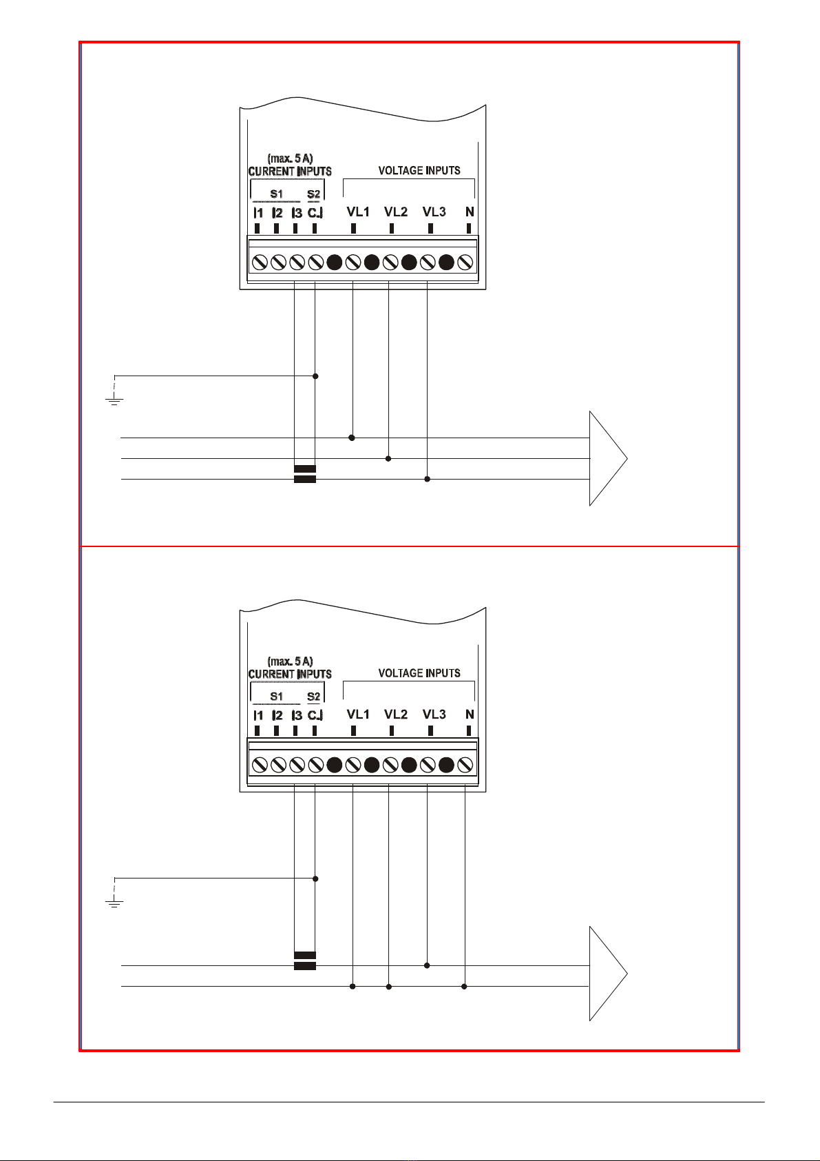
ELM
CURRENT
INSERTION
ON THREE PHASE LINE WITH 2
CT
(insertion
AARON)
L1
S1
P1
L2
L3
N
S1
S2
P1
P2
LOAD
ELM
VOLTAGE INSERTION
ON
THREE PHASE LINE WITH 3
WIRES
WITH 2
VT
This insertion is possible only
with
the internal CT version (-t
suffix).
S1 S2 S1
S2
P1 P2 P1
P2
L1 LOAD
L2
L3
ELM
INSERTION ON BALANCED
THREE
PHASE LINE WITH 3 or 4
WIRES
On line with 3 wires (without neutral
or
with neutral not
supplied)
the N terminal must not be
connected
ELM-96
instruction manual
IM425-U v3.1
pag. 5
L1
L2
L3 S1
S2
P1
P2
LOAD
ELM
INSERTION ON SINGLE
PHASE
LINE
Only for model with
phase-neutral
power supply (Vaux
L3-N)
L S1
S2
N P1
P2
LOAD

ELM-96
instruction manual
IM425-U v3.1
pag. 6
FRONT PANEL DESCRIPTION
DESCRIPTION:
A: Push-button for visualising of the three phase system parameters with the corresponding indication LED.
By pressing during 5 seconds, user accedes to programming the instrument (SETUP).
B: Push-button for selecting the measures to visualise on display E.
C: LED’s for indicating the measures visualised on display E and the eventual multiplier factor of each parameter
(reading k =kilo x1000).
D: LED for indicating the visualisation of the memorised peak values.
E: Three displays for visualising the measures, subdivided by phases. Should the LED ΣL be glowing, it indicates
the three-phase system value of the selected parameter.
A+B: By pressing the two keys simultaneously at the visualisation mode, it accedes to the visualisation of the
memorised peak values.

MENU OF INSTRUMENT PROGRAMMING (
SETUP
)
After the connecting the power supply to the instrument and waiting few seconds (all LED’s will glow and the first
indication of the firmware appears on the display and all segments will glow later), press and keep pressing the key A
during 5 seconds, when the message
seT
UP will appear on the display E.
The values set are hold also in absence of the auxiliary power supply.
SET GENERAL PARAMETER (SET
UP
)
Entry to menu:
seT
UP Æ
seT
Up
RESET
SET
DO1
SET
DO2
SET
HR_
ELM-96
instruction manual
IM425-U v3.1
pag. 7
DO_ OFF
OFF
SET CT Increase
Set CT ratio
from 1 to
2000
Decrease
SET VT Increase
Set VT ratio
from
0.1
to
400.0
Decrease
seT AV9
T Increase
Set average time
from 1 to
30
minutes Decrease
seT 3pH
BALANC
Set connection
UN_BAL
Type 1PH
L3
seT
MDE
-3-
Set wiring connection
type
-4-
seT SYN
MDE
L3
Set synchronism
50
type
60
seT SCHROLL
ON
OFF
SET PAS Increase
Set Password
OFF
- 0002
÷
9999
Decrease
Confirm and end of general settings
- Programming of the transformation rate of the external CT’s
The programming of the CT’s rate considered as the rate between primary and secondary (example: with CT 1000/5, we
must set 200), must be done with the push-button on the front panel.
By pressing the key A again it will appear the message CT (current transformer) and the value of the transformation rate
(set to 1 by the manufacturer). To increase the value press the B button while to reduce the value press the A button with
B already pressed (the variation is unit for unit). To increase the speed up the value setting, it’s necessary to hold
pressed the B or the couple A and B buttons, the variation will happen successively by tens and hundreds. To come back
to increase or to reduce the value on unit by unit way, it’s necessary to release and to press the key again. To confirm the
value set press the A button; in this way the instrument will pass to the successive programming.
If no key is pressed during a 10-second interval of time, the instrument will exit automatically from programming, without
saving the selected value.

- Programming of the transformation ratio of the external voltage transformers
After the precedent programming phase, on E display will appear the inscription VT (voltage transformer) and the value
of the transformation rate of the external TV (set to 1 from the constructor), considered as the rate between primary and
secondary (example with TV 15/0.1 kV the value will be 150).
In the same way at the programming of the CT rate will be possible to set this value. If the external TV are not used the
value to set will be 1. To confirm the value press the A button.
Programming of the average time (
seT
AVG
T’
)
After the programming phase previously described, pressing another time the A key, on the E display will appear the
message AVG
T’
and the average time settable from 1 to 30 minutes. To increase the value press the B key. To
decrease it, press the A and B keys together (from the condition of B pressed). To confirm it press the A key.
The average time is the time used to calculate the average parameters (avg) and the maximum demand (maxD).
Programming insertion mode
It’s possible to set the following mode of insertion:
UN_BAL
in a unbalanced three-phase system (default),
BALANC
in
a balance three phase system and 1PH
L3
in a single phase insertion.
In the 1PH mode are displayed only the measures of l3 phase and the relative hour counter; the status of phase rotation
is not displayed.
In the
BALANC
the current and the power factor of the L3 phase are used for the calculation of L1 and L2 measures.
Programming wiring connection mode
This setting allows to definite the wiring type connection. It’s possible to chose 3 wires or 4 wires. With the 4 wires
connection the neutral parameter are displayed and enabled to use for the digital outputs settings.
Programming of the synchronism type
In this setting for the synchronization type, it’s possible to choose
L3
to use the external frequency (on L3 phase) or
50
,
60
Hz to use the internal clock.
Activating or cancelling the automatic scrolling
This allows selecting ON for activating or OFF for cancelling the automatic scrolling of the measures visualisation.
Programming of the Password
The instrument is supplied without password. When a password (from 0002 to 9999) is set, using the B (to increase), A e
B (to decrease) and A (to confirm) keys, only who know this value can to enter in the setup. The password, in fact, is
required all the time that someone try to enter in the setup (pressing the A key at least 5 seconds). If the password is
wrong, the message
PASS
ERR will appear on F display and the instrument go back to the measures visualization. To
input the password, when required by the instrument, at the enter of the setup, use the A, B and C keys as the same way
done previously.
PEAK VALUES AND ENERGY COUNTERS RESET (
RESET
)
Enter in setup mode, press the B key up to show the message
ReseT
on the E display, press the A key, on the display
will appear RES
ALL
NO, press the B key another time, the message commute in RES
ALL
yes
, confirming with
the A key all stored data will be deleted. Automatically the instrument come back to the measure visualization.
ELM-96
instruction manual
IM425-U v3.1
pag. 8
Entry to menu:
seT
UP Æ
seT
Up
RESET
SET
DO1
SET
DO2
SET
HR_
---
OFF OFF (the visualization depends on the settings and the I/O status)
To enable the chosen type, press the B key to change the indication on display G from NO to
yes
. Confirm enabling
cancellation, by pressing the A key. The indication on E display change from
yes
to
---
.

PROGRAMMING OF THE DIGITAL OUTPUT (SET DO1 SET
DO2
)
This setting is enabled only in the model with digital outputs (-p suffix in the order).
The DO1 and DO2 digital outputs can be used to signal alarms (ALR) using a comparing with two adjustable threshold
for each output. The DO1 modality setting is independent from DO2. In the menu SET DO1 and SET DO2 it’s possible
to program the function of all digital outputs. In these menus are available the following modality: ALR SYS
3PH
and
ALR SYS
123
. With ALR SYS
3PH
the digital output will function as alarm verifying that the three phase value
(average) doesn’t exceed the threshold set (ALR HI and ALR LO). With ALR
PH_ 123
the digital output will
function as alarm verifying that the maximum value of the single phases doesn’t exceed the maximum threshold set
(ALR HI) and that the minimum value of the single phases doesn’t come down the minimum threshold set (ALR
LO
).
The activation of the alarm output will come after some seconds of delay set (ALR
DL
).
ELM-96
instruction manual
IM425-U v3.1
pag. 9
Enter to menu:
seT
UP Æ
seT
Up
RESET
SET
DO1
SET
DO2
SET
HR_
---
OFF OFF (the visualization depends on the settings and the I/O status)
ALR SYS
3PH
To choose the output modality
ALR
PH_
123
ALR
SEl uLN
To chose the parameter
ALR
SEl
AMP to control
ALR
SEl VLL
(see variable list)
ALR SEL FRE (only for ALR SYS
3PH
)
AlR sel
PH_
Set maximum alarm threshold Increase
ALR HI Decrease (after
0
there is
OFF
)
Set minimum alarm threshold Increase
ALR LO Decrease (after
0
there is
OFF
)
Set delay Increase
ALR
Dl
Decrease
ENTER IN THE SETUP
Confirm and end of digital output settings.
From the measures visualization, press the A keyfor at least 5 seconds, the message
SeT
Up will appear on the E displays.
CHOOSE THE DIGITAL OUTPUT TO PROGRAM
Press repeatedly the B key until the message SET DO1 (DO1 output) or SET DO2 (DO2 output) appears on the E
display. Press the A key to select this setting.
SELECT THE MODALITY OF FUNCTIONING OF THE DIGITAL OUTPUT
To select the functioning mode, using the B key: ALR SYS
3PH,
(alarm on three phase value) and ALR
PH_
123
(alarm on minimum and maximum single phase value). Press A key to confirm.
CHOOSE THE PARAMETER TO LINK TO THE DIGITAL OUTPUT
With an alarm modality set, it’s necessary to select the parameters associated to the alarm output; by pressing the B key
until the parameter choice appears on the third part (L3) of E display and the glowing the corresponding led on the D bar.
Press A key to confirm the set.
SET THE HIGH AND THE LOW THRESHOLDS
On E display will appear the message ALR Hi with the high threshold value; confirming with the A key on the same
display will appear the message ALR LO with low threshold value. The B key (to increase), A and B keys together (to
decrease) are used to set the high and the low thresholds values. The range depends by the parameter and it is linked to
the CT and VT ratios. Pressing A key to confirm.
The threshold set is linked with CT and VT ratios, for this reason it’s necessary to make this operation after the
programming of the CT and VT. The end scale value must be confirmed when CT and VT ratios are modified.
The low threshold will be lower than high threshold. If the high threshold is set as OFF the low threshold will have the
range of the high threshold.
SET THE DELAY TO THE DIGITAL OUTPUT ACTIVATION
Now it’s possible to set the delay that will pass between the alarm condition set and the activation of digital output. On E
display will appear ALR DLY and the value expressed in seconds (range 1÷900). The modification of the value is done
in the same way of the threshold set. With the confirmation (A key) the set is complete.
The programming will be referred to the digital output indicated on E display (DO1 o
DO2
).
With only the HI threshold set, the alarm condition is activated when the parameter set in alarm exceed the threshold.
The digital output is enabled only if the alarm condition remain activated for all delay time set. From the activation of the
digital output, the restore is automatic when the parameter decreases below the hysteresis value.
ELM-96
instruction manual
IM425-U v3.1
pag. 10
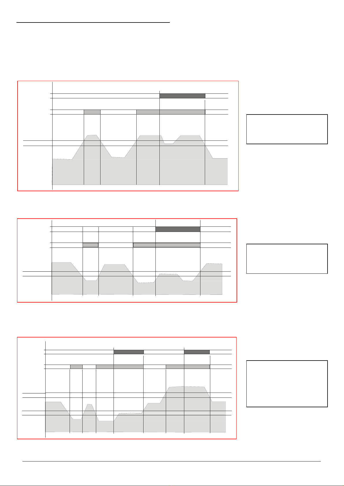
Digital
outp ut
Alarm
Threshold
HI
Hysteresis
HI
t <
dela y
de l ay
Functioning for
exceeding the
maximum threshold
With only the LO threshold set, the alarm condition is activated when the parameter set in alarm drop below the
threshold. The digital output is enabled only if the alarm condition remain activated for all delay time set. From the
activation of the digital output, the restore is automatic when the parameter grow above the hysteresis value.
Digital
ou tp ut
Ala rm
Hysteresis
LO
Threshold
LO
t <
de la y
de lay
Functioning for
dropping above
minimum threshold
With both LO and HI threshold set, the alarm condition is activated when the parameter set in alarm is outside from the
values band limited by LO and HI thresholds. The digital output is enabled only if the alarm condition remain activated for
all delay time set. From the activation of the digital output, the restore is automatic when the parameter return inside the
values band limited by LO and HI thresholds.
Digital
ou tp ut
Ala rm
Threshold
HI
Hysteresis
HI
Hysteresis
LO
Threshold
LO
t
<
de l ay
del ay
del ay
Functioning for
exceeding or dropping
by the band defined by
maximum and
minimum threshold

PROGRAMMING OF THE HOURS COUNTER (SET
HR_
)
ELM-96
instruction manual
IM425-U v3.1
pag. 11
The hour counter will be increased when the measure of the parameter will exceed the set threshold value. The threshold
set is applied to the system value of the parameter selected. For the frequency the referring it’s the same to the measure
of the L3 phase.
seT
UP Æ
seT
Up
RESET
SET
DO1
SET
DO2
SET
HR_
---
OFF OFF (the visualization depends on the settings and the I/O status)
HR_ SEl
VLN
HR_ SEl
AMP To chose the parameter
HR_ SEl VLL
(see the variable list)
HR_
SEL
FRE
Set the threshold Increase
HR_
HI Decrease
Confirm and end of hour counter settings.
SELECT THE PARAMETER TO LINK TO THE HOURS COUNTER
From the previous setting, pressing the B key it’s possible to set the hours counter: the message SET
HR_
appears on
the E display. Press the A key to define the parameter to link to the hours counter. Press more time the B key to select
the parameter and the A key to confirm it.
SET THE THRESHOLD
Subsequently it’s necessary to set the threshold using the B key (to increase) and A and B keys (to decrease). Confirm
with A key.
I/O INFO PAGE
After the hour counter set, the I/O info page appears in E displays: on the second part (L2) the status of the first digital
output (DO1), on the third part (L3) the status of the second digital output (DO2).
VARIABLE LIST
VLN
three-phase voltage
AMP three-phase current
VLL
phase to phase voltage
FRE frequency
PH_
check the rotation phase voltage connection

MEASURES VISUALISATION
The measures reading is visualised on the display E, showing the three phase measures (L1, L2 y L3 respectively) of the
indicated parameter by the C LED. For measuring the phase to phase voltage (V L-L), the three measures are understood
V L1-L2, V L2-L3, V L3-L1 respectively, as indicated on the front plate.
The selection of the parameter to be visualised is made by pressing the key B. It will be indicated by the C LED.
By pressing the key A, the selected parameters will be visualised on display E, as three phase values (average of the
individual phases for voltages and currents) with the corresponding lighting of the LED, placed internally in the key.
With LED ΣL turned off and unbalanced three phase system mode
(UNBALANC) are displayed in the following
sequence:
- LED VL-N ON: On the display are showed the phase voltages
- LED VL-L ON: On the display are showed the phase to phase voltages
- LED A ON: On the display are showed the phase current
- LED Hz ON: on L3 display is showed the frequency measured on L3 phase, on L1 display will appear the
message
PHASE ROTATION
with a bright dash that rotate clockwise to indicate that the
phase rotation is correct, or the message ERR if the phase rotation is wrong.
- LED h ON: On the display are showed the phase hour counters HR1, HR2,
HR3.
The reading of the
meters uses the 6 digits (maximum reading 99999.9) of the E display the measure comes
visualised in such a way that, the display L1 will show the first 3 digits, the display L2 the second
3 digits and the display L3 the identification of the corresponding hour meter (HR1, HR2,
HR3
).
Each hour counter is activated when the measure of phase corresponding to the selected
parameter exceed the threshold set (see SET
HR_).
The measure is expressed in hour
(integer) and tenths of hours (decimal).
By pressing the A key the LED ΣL is enabled and the system values are displayed.
Please note that the unit value may be expressed in kilo, when the corresponding LED C are glowing (indicated in the
front plate as k).
The visualised frequency is referred to the line L3.
ELM-96
instruction manual
IM425-U v3.1
pag. 12
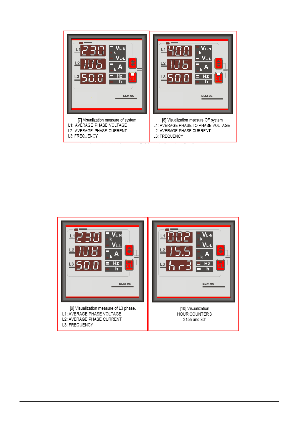
Visualizations parameter of system (LED ΣL on),
V
L-N
k
V
L-L
k A
k
VL-N
V
L-L
In balanced three phase system mode
(BALANC)
are available only the visualization [7] and [8]:
In single phase mode
(!PH
L3
) the pages displayed are the following:
ELM-96
instruction manual
IM425-U v3.1
pag. 13

V
L-N
k
ELM-96
instruction manual
IM425-U v3.1
pag. 14
VISUALISING THE INSTANTANEOUS AND AVERAGE PEAK (MAXIMUM) VALUES
By pressing the A and B keys simultaneously, the instrument enters into the
visualisation of the peak (maximum) values: The LED D will glow. The
memorised peak (maximum) values, which might be selected by the B key,
will be shown on the display E.
The indication of the value and the value itself will be visualised alternatively
on the display E.
If no key is pressed during an interval of time of 10 seconds, the instrument
will return automatically to the visualisation of measures.
There are two types of the maximum memorised values:
The instantaneous maximum memorised value is the maximum reached
value of the parameter, during 1-second al least.
The average maximum values (maximum demand) memorise the maximum
average value of the parameter, reached during the average time.
The integration for calculating the average values is synchronised every
time that the instrument is switched on.
During the visualisation of the maximum memorised values, the values are visualised by alternating the indication of the
visualised parameter with the measured values.
The maximum values of the parameters, which are selectable with the B key, are as follows:
Pa
r
amete
r
Dis
p
la
y
Si
g
nallin
g
LED
VL-N maximum instantaneous PEA
HI
VL-N
VL-N minimum instantaneous
Pea LO
VL-N
VL-L maximum instantaneous PEA
HI
VL-L
I phase maximum instantaneous PEA
LO
A
I phase average maximum AVG
HI
A
NOTE regarding the measures
The refresh time of display is lower than 1 second and it corresponds to the processing time of measure according to the used
measuring methodology, allowing a comfortable reading of values, also in presence of unexpected deviation of the measured
parameters.
Should the case be that the instrument is being used in a single-phase line, please bear on mind that the valid values are referred to
phase L3.
Other visualised values shouldn’t be considered, since they correspond to three-phase system.
In case that the indicated measures aren’t reliable or they are absurd, it’s important to check carefully the current and voltage inputs
connection, so as the phase sequence. Check that current and voltage correspond to the same phase (on input L1 it will be connected
phase voltage L1 and the CT will be placed on phase L1), thence terminal S1 of CT will be wired to the relative terminal S1 on the
instrument.
If the secondary of the CT is connected to other instruments also, it can be experienced some measuring problems, according with the
typology of current inputs. Should that be the case, the user should select the option of the instruments type (T) with internal CT’s.

TECHNICAL CHARACTERISTICS
MEASURES, ACCURACY
Voltage True rms for the phase, phase to phase and three-phase voltage
Total measuring range: 20÷500V trms phase-phase - 290V rms phase-neutral, depending always to the
power supply voltage.
Visualization (0,02÷50,0kV) – measuring accuracy: ±0,5% ±1 digit
Current True rms for the phase and three-phase currents.
Measuring range: 0,02÷5A trms - accuracy: ±0,5% ±1 digit
Visualization 0,02÷9990A
Frequency Frequency of the phase L1 – measuring range: 45÷65Hz
accuracy: ±0,5% ±1 digit
AUXILIARY POWER SUPPLY -INPUTS
Aux. power supply Standard 380-415V ±15% - options 100-125 / 220-240V ±15%
Frequency 45-65Hz - absorption 3VA
Voltage taken from the measuring voltage inputs
Voltage inputs from 20 to 500V phase-phase (always depending on the auxiliary supply); permanent overload +20% -
impedance at the input: 1 MΩ
Three-phase wiring with 3 or 4 wires, and single-phase wiring
MV connection through external VT
w
ith prog
r
ammable transformation ratio from 1 to 400
Current inputs From 0,02 to 5A; permanent overload 30% - from external CT’s with secondary 5A
primary programmable from 5 to 10000A – self consumption <0,5VA
GENERAL
Display and keyboard 3 display with red LED of 10 mm each, made of 3 digits of 7 segments
2 ke
y
s for selection of measures and programming
Mechanical Protection degree: IP52 frontal - IP20 enclosure and terminals - weight: approx. 0,5 kg.
Wiring through terminals for screws, cross section cable of 2,5 mm2
Self-extinguishing plastic enclosure –
ELM-96: Flush mounting DIN 96x96mm, depth 56mm
Environment Working temperature: -10÷60°C; relative humidity <90%
Storage temperature: -25÷70°C
Isolation test: 3 kV during 1 minute
Standards of reference
and Marking
CEI EN 50081-2; CEI EN 61000-6-2;
CEI EN 61010-1
ELM-96
instruction manual
IM425-U v3.1
pag. 15

ELM-96 instructionmanual IM425-U v3.1 pag.16
DIMENSIONS
9 56
96
Drill panel
96
96
9
92
ELM-96
R3
avg
92
2
For other applications, please contact with ELCO technical assistance department.
Via Lago di Molveno, 2 – 36 15 Schio (VI)
Tel. +39 445 661722 –Fax +39 445 661792
http://www.elco-italy.com
E-mail: info@elco-italy.com; s[email protected]
Table of contents
Other elco Multimeter manuals


