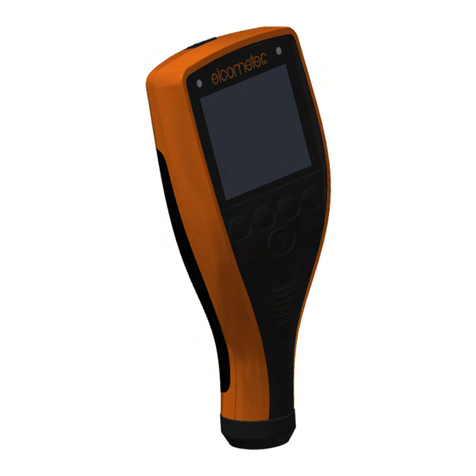
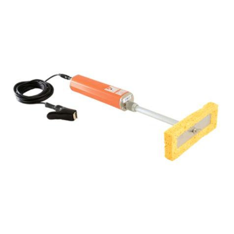
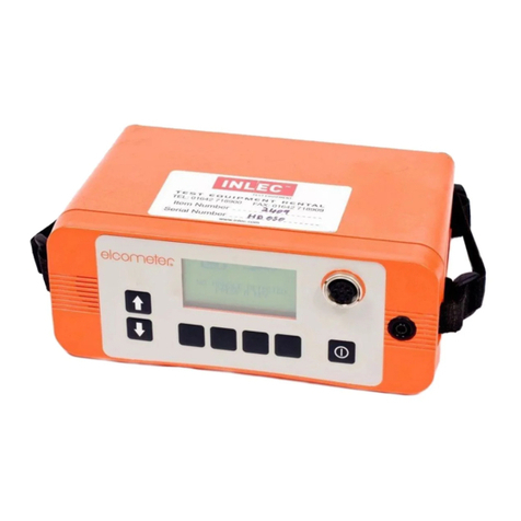
Elcometer 136 User manual

Operating Instructions
for the
Elcometer 136
DC Portable Holiday Detector

SAFETY WARNING
The detector generates a high voltage at the probe tip,
up to 30,000 volts.
The equipment should be used with extreme care,
following the instructions given in this Manual.
All CE marked Elcometer 136 Holiday Detectors meet
the emc directive 89/336/EEC, amended 92/31/EEC &
93/98/EEC.
However, due to its method of operation, the Detector will
generate broadband RF emissions when a spark is produced
at the probe, i.e. when a defect in the coating is located. These
emissions may interfere with the operation of sensitive
electronic apparatus in the vicinity.
In the extreme case of a continuous spark of length 5mm, the
magnitude of emissions at a distance of 3m was found to be
approximately 60dBµV/m from 30MHz to 1000MHz.
It is therefore recommended that this equipment is not
operated within 30m of known sensitive electronic equipment
and that continuous sparks are not deliberately generated by
the User.
is a registered trademark of
Elcometer Instruments Ltd.
©Elcometer Instruments Ltd. England 1994, 1996, 1998
All rights reserved. No part of this document may be
reproduced, transmitted, transcribed, stored (in a retrieval
system or otherwise) or translated into any language in any
form or by any means (electronic, mechanical, magnetic,
optical, manual or otherwise) without the prior written
permission of Elcometer Instruments Ltd.
!
Doc.No. = TMA-0146 Issue 04
Text with Cover No. = 4399

CONTENTS
1.0 SAFETY GUIDE 1
1.1 Do Not 1
1.2 Do 2
2.0 INTRODUCTION 3
3.0 EQUIPMENT IDENTIFICATION 3
3.1 Control Panel 3
3.1 Connections and Terminals 4
4.0 DETAILED OPERATION 5
4.1 Test Batteries 5
4.2 Connect Leads 5
4.3 Select Probe 6
4.4 Earth to Substrate 6
4.5 Check the Earth Connection 6
4.6 Set the Test Voltage 7
4.7 Set Alarm Sensitivity 7
4.8 Detecting Holidays and Other Coating Flaws 7
4.9 Moving Work Position and Finishing Work 7
4.10 Static Electricity 8
5.0 TEST VOLTAGE & SENSITIVITY 9
5.1 Dielectric Strength 9
5.2 Determining the Voltage Limits 10
5.2.1 The Lower Limit 10
5.2.2 The Upper Limit 11
5.3 Setting Alarm Sensitivity 11
6.0 PROBE SELECTION 13

7.0 TROUBLESHOOTING 13
7.1 LCD Display Related Problems 13
7.2 Alarm Related Problems 14
7.3 Special Considerations 15
7.3.1 Conductive Coatings 15
7.3.2 Concrete Substrates 16
8.0 MAINTENANCE 17
8.1 Battery Maintenance 17
8.1.1 Charging the Battery 17
8.1.2 Replacing the Battery 17
8.1.3 Deep Discharged Battery 18
8.2 Lengthening the Earth Lead 18
8.3 Routine Checks 18
9.0 PROBE, SPARES AND
ACCESSORIES GUIDE 19
9.1 Right Angle Probes 19
9.1.1 Spare Electrodes for Right Angle Probes 19
9.2 Circular Brush Probes 20
9.3 Rolling Spring Probes 21
9.4 Extension Pieces 22
9.5 Spares Numbers 22

Figure 1
Summary of Operation
Replace or
Recharge
Batteries (8.0)
Read Safety Guide (1.0)
Batteries
OK?
Test Batteries (4.1)
Connect Leads (4.2)
Select Probe (4.3)
Earth to Substrate (4.4)
Check Earth (4.5)
Earth
OK?
Set Alarm Sensitivity (4.7)
Set Test Voltage (4.6)
Operation
OK?
Inspect Coating for Flaws (4.8)
End Work
YES
NO
YES
YES
NO
NO

1.0 SAFETY GUIDE.
Due to the method of testing for coating flaws, this equipment
outputs a voltage of up to 30kV, i.e. 30,000 volts, on the high
voltage probe. Therefore, if the User touches the probe, they
may receive a mild electric shock. However, due to the current
being very low, this is not normally dangerous.
Due to coating flaws being indicated by an electrical spark this
equipment is unsuitable for use in certain environments, e.g.
an explosive atmosphere.
Explanation of Warning Symbols.
(Yellow background with black outline and symbol).
CAUTION - Risk of electric shock.
(Yellow background with black outline and symbol).
CAUTION - please follow the safety guidelines as
detailed in Sections 1.1 & 1.2.
To minimise injury and damage, the following guidance should
always be observed.
1.1 Do Not.
DO NOT use the equipment in any combustible, flammable or
other atmosphere where an arc or spark may result in an
explosion.
DO NOT carry out tests close to moving machinery.
DO NOT use in a precarious, wobbly or elevated situation from
which a fall may result in injury, unless a suitable safety
harness is used.
DO NOT use in rain or a damp atmosphere.
DO NOT use the equipment if you have a pacemaker or heart
condition.
!
1

DO NOT clean the instrument or cables with any type of
liquids. Cleaning of the instrument to remove overspray and
spots of coatings is a Service requirement. Please contact your
local Distributor or Elcometer Instruments Ltd.
1.2 Do.
DO read these instructions carefully before commencing to
use the equipment.
DO consult the plant or Safety Officer before carrying out the
test procedure.
DO wear rubber gloves.
DO undertake testing well clear of other Personnel.
DO work with an assistant, to keep the test area clear and to
help with the testing procedure.
DO check that there are no solvents or other ignitable materials
in the test area, particularly in confined areas such as tanks.
DO switch the detector off and disconnect the leads when the
work is finished and before leaving it unattended.
DO ensure that the earth lead is connected to the conducting
substrate prior to switching the detector on.
DO only use on coatings which are cured, thickness tested
and visually inspected and accepted.
DO only use on coating thicknesses of at least 200 microns
(0.008"). For thinner coatings, use the wet sponge method with
the Elcometer 204 and 269. Use with care for thicknesses
between 200 and 500 microns (0.008 to 0.020").
DO be aware of static build-up on the work surface. To reduce
the risk of static shock, wear rubber gloves and take special
care when leaving confined areas.
2

2.0 INTRODUCTION.
The Elcometer 136 DC Portable Holiday Detector detects flaws
on non-conductive coatings which are applied to conductive
substrates. The coating should be at least 200 microns (0.008")
and preferably over 500 microns (0.020") thick.
The Elcometer 136 is earthed to the substrate and passes a
high DC voltage through a probe to the coating surface. When
the probe passes over a coating flaw the electrical circuit is
completed. The Elcometer 136 gives an audible and a visual
alarm and may produce a spark at the flaw.
3.0 EQUIPMENT IDENTIFICATION.
3.1 Control Panel.
Figure 2 - Control Panel Layout
1. -LCD display of output voltage
2. Voltage Voltage control
3. ALARM Visual alarm (illuminates when flaw detected)
4ON Press to switch on
5. OFF/Test Press to switch off. Press again for tests
6. Sensitivity Sensitivity control for alarm
7. -Battery level indicator
High Voltage DC
Holiday Detector
Voltage
Sensitivity ON
OFF
Test
À
Á
Â
Ã
Ä
Å
kV
Batt
F
E
Æ
3

3.2 Connections and Terminals.
Figure 3 - Side Connections and Terminals Layout
1. High voltage probe connection
2. Fuse and fuse holder (1.6A T-type fuse, supplied separately)
3. Earth lead terminal
4. Nut securing battery pack
5. Slide-out battery pack
6. Battery charger connection
À
Á
Â
Ã
Ä
1.6 A
4

4.0 DETAILED OPERATION.
ALWAYS consult the SAFETY GUIDE before using this
equipment.
See Figure 1 for Summary of Operation.
If using the Elcometer 136 in the carry case, pass the earth
lead through the loop on the side of the case. This reduces
the possibility of the earth lead becoming detached.
For the Elcometer 136 to function correctly, the substrate must
be a conductor and the coating must be an insulator.
4.1 Test Batteries.
Turn ‘Voltage’ fully anti-clockwise to set the voltage output to
zero.
Press [ON] to switch the instrument on.
Check the battery level indicator. The black segments indicate
the battery power level (‘F’ reducing to ‘E’). If no black
segments are displayed, the battery should be replaced or
recharged. See Section 7.0.
4.2 Connect Leads.
Press [OFF/Test] to switch the instrument off.
Turn ‘Voltage’ fully anti-clockwise to ensure that the
instrument is safe.
Connect the red, high voltage, probe handle and lead to the
high voltage probe connection.
Connect the earth lead (green connector, green and yellow
wire) to the earth lead terminal.
5

4.3 Select Probe.
Select the correct probe and attach it to the high voltage probe.
Type of Surface Recommended
Probe Notes
Small area, complex
surface, general
applications
Band brush probe Provides low contact
pressure
Large surface areas Right-angle brush
probe
Available in different widths,
with conductive rubber strip
for light contact and
phosphor bronze wire for
medium contact
Inside of pipes, 38 to
305mm (1.5 to 12")
diameter
Circular brush
probe
A phosphor bronze circular
brush with a 250mm
extension piece supplied as
standard
Outside of pipes, 50
to 1000m (2 to 39")
diameter
Rolling spring
probe
A phosphor bronze spring
with a 250mm extension
piece supplied as standard
Table 1 - Probe Selection Table
4.4 Earth to Substrate.
Clamp the earth lead to the exposed substrate.
4.5 Check the Earth Connection.
Holding the probe by its handle and in free air, press [ON] to
turn the detector on.
Turn ‘Voltage’ clockwise until the LCD displays ‘1kV’ and then
turn ‘Sensitive’ fully clockwise.
Place the probe on bare substrate or the earth connection.
The alarms should sound and light up; the neon light in the
probe handle should glow, showing that the connection is
good. If not, repeat this Section. If the earth connection is still
not satisfactory, please refer to Section 6.0.
6

Press [OFF/Test] to switch the instrument off. Turn ‘Voltage’
and ‘Sensitivity’ fully anti-clockwise.
4.6 Set the Test Voltage.
Holding the probe in free air press ‘ON’ to turn the detector
on.
Turn ‘Voltage’ clockwise until the required test voltage is
indicated on the LCD display. See Section 5.0 for background
information on the Test Voltage.
4.7 Set Alarm Sensitivity.
Use ‘Sensitivity’ to set the sensitivity.
‘Sensitivity’ turned fully clockwise gives the maximum
detector sensitivity and the lowest threshold current
‘Sensitivity’ turned fully anti-clockwise gives the minimum
detector sensitivity and the highest threshold current
See Section 5.0 for background information on Sensitivity.
4.8 Detecting Holidays and Other Coating Flaws.
Place the probe on the test surface. Keep the probe in
contact with the surface and move it at a speed of
approximately one metre every four seconds, 0.25m/s (10"/s).
One or more of the following indicates a flaw:-
- A spark between the probe and the surface
-‘ALARM’ indicator flashes
- The audible alarm sounds
- The output voltage, indicated on the LCD display, drops
substantially
- The probe neon indicator glows
4.9 Moving Work Position and Finishing Work.
Always turn the detector off and set the voltage to zero before
disconnecting the leads, when work is finished or when leaving
work unattended.
When the earth has been attached at its new position, the
connections should always be checked. See Section 4.5.
7

4.10 Static Electricity during Testing.
As the probe is moved over the surface of a coating, a static
charge builds up which can:
- cause objects in contact with the surface to become
charged with the same polarity
and
- induce an opposite charge on nearby objects electrically
insulated from the surface.
The following examples demonstrate the possible effects on
the Operator if inside a short pipe insulated from the ground.
Operator without rubber gloves
or footwear:
The Operator is touching the
coating
The body then becomes charged
at the same polarity as the coating
No shock if the coating is touched
The Operator gets a shock
steppingfromthepipetothe
ground
Operator wearing rubber gloves
and footwear:
The rubber gloves and footwear
insulate them from the coating
The body becomes charged with
the opposite polarity to the
coating
If an uninsulated part of the
Operator touches the coating,
discharge will cause a shock
The Operator gets a shock
steppingfromthepipetothe
ground
Avoiding Static Shock.
A conductive strap between the Operator and the ground will
stop the body from becoming charged. Rubber gloves and
footwear should also be worn. There may still be a shock inside
the pipe if an uninsulated part of the body touches the charged
coating.
8

5.0 TEST VOLTAGE AND SENSITIVITY.
For effective testing, the output voltage must lie between lower
and upper limits.
The lower voltage limit us the voltage required to break down
the thickness of air equivalent to the coating thickness. See
Section 5.2.1.
The upper voltage limit is the point at which the coating would
break down. See Section 5.2.2.
The following describes how the band of safe, but effective,
voltage outputs may be determined.
5.1 Dielectric Strength.
All material will conduct electricity if a high enough voltage is
applied. However, with insulators, the voltage level required to
achieve a current flow is usually destructive.
The voltage at which a thickness of material breaks down is
called the dielectric strength. This is usually expressed as the
voltage per unit distance, e.g. kV/mm.
Its value depends on the type of applied voltage, e.g. AC, DC
or pulsed, temperature and thickness.
Figure 5 shows the relationship between breakdown voltage
and thickness for materials of different dielectric strengths. The
dielectric strength of coating materials usually lies in the region
of 10 - 30kV/mm.
9

Figure 5
Breakdown Voltage Against Thickness for Materials of
Different Dielectric Strengths
5.2 Determining the Voltage Limits.
5.2.1 The Lower Limit.
The lower voltage limit for effective operation is the dielectric
strength of air (1.3 to 4kV/mm) multiplied by the thickness.
If the coating thickness can be determined, read the lower
limit value from Figure 5, using the line marked AIR. For
instance, if the coating thickness is 1.0mm then the lower limit
is ~ 4.5kV.
If the coating thickness cannot be determined then the
minimum value has to be established experimentally.
Turn the ‘Voltage’ to zero and place the probe over an
uncoated area of substrate at the normal height of the coating
surface.
10

Turn ‘Voltage’ up slowly and steadily until a spark is
produced.
Note the voltage. This voltage forms the lower limit.
5.2.2 The Upper Limit.
The upper voltage limit is the dielectric strength of the material
multiplied by its thickness.
The following are methods for determining the upper voltage
limit.
The job specification - if available and a test voltage is stated.
The dielectric strength - if specified for the applied coating.
Measure the thickness of the layer and refer to Figure 5.
Alternatively, calculate the maximum voltage, allowing for
variations in the coating thickness. Note that 1kV per mm is
equivalent to 25.4V per mil/thou. This method is only suitable
if the dielectric strength values were determined for a DC
voltage.
Experimentation - touch the probe on an unimportant area of
the work piece. Increase the voltage slowly and steadily until
a spark passes through the coating. Note the displayed
voltage. The dielectric strength can be calculated by dividing
the voltage by the material thickness.
Tables and formulae - from established Codes of Practice,
e.g. NACE and ASTM. See Tables 2, 3 and 4.
5.3 Setting Alarm Sensitivity.
Sensitivity determines the point above which the alarms are
triggered when a flaw is detected. It is adjustable to allow for
the effects of any electrical leakage, through the coating or
moist air, which would unnecessarily trigger the alarms.
11

Table 2 - kV Values from ASTM G62-87
microns kilovolts thou kilovolts
100 1.04 5 1.17
200 1.47 10 1.66
300 1.80 15 2.03
400 2.08 20 2.34
500 2.33 25 2.63
600 2.55 30 2.88
700 2.76 35 3.11
800 2.95 40 3.32
900 3.12
1000 3.29
Table 3 - kV Values from ASTM G62-87
mm kilovolts thou kilovolts
1 7.84 40 7.91
2 11.09 80 11.18
3 13.58 120 13.69
4 15.69 160 15.81
5 17.54 200 17.68
6 19.21 240 19.36
7 20.75 280 20.92
Table 4 - kV Values from NACE RP0199-88
mm thou kilovolts
0.20 to 0.28 8 - 11 1.5
0.30 to 0.38 12 - 15 2.0
0.40 to 0.50 16 - 20 2.5
0.53 to 1.00 21 - 40 3.0
1.01 to 1.39 41 - 55 4.00
1.42 to 2.00 56 - 80 6.0
2.06 to 3.18 81 - 125 10.00
3.20 to 3.43 126 - 135 15.00
12

6.0 PROBE SELECTION.
Table 1 (Section 4.3.) shows the most suitable probe to use
depending on the surface to be tested. Extension pieces and
connectors are also available if a long reach is required. See
Section 9.0.
Use only fittings supplied by Elcometer Instruments Ltd.
7.0 TROUBLESHOOTING.
7.1 LCD Display Related Problems.
LCD Display Does Not Function
Possible Reason Solution
The detector is not turned on Press ‘ON’ to switch on
The battery is flat, as indicated by
the battery condition monitor
Recharge or replace the battery,
see Section 7.0
Connectors between the detector
and the battery are flattened
Remove the battery, see Section
8.0 and carefully lever up the
contacts using pliers or a
screwdriver
Fuse not fitted, or blown Fit or replace fuse - see Figure 3
LCD Display Shows ‘-1’ Continuously
Possible Reason Solution
Voltage higher than LCD display
range
Decrease the output voltage or
use a larger capacity detector
Displayed Voltage Drops During Test
Possible Reason Solution
Conductive surface or probe
surface area too large
Use a smaller probe, see Section
4.3, or decrease the output
voltage. See Section 7.3
13

Displayed Voltage is Higher than that at Probe Tip
Possible Reason Solution
Damaged high voltage lead Replace lead
Missing/ broken neon indicator Replace neon indicator
Poor earth connection Check connections. See Section 4.5
7.2 Alarm Related Problems.
Alarm Sounds Continuously
Possible Reason Solution
Conductive coating See Section 6.4.1
Sensitivity too high Reduce s ensitivity by turn ing
‘Sensitivity’ anti-clockwise
Probe movement too fast Move at 0.25m/s (10"/s)
Probe surface area too great Use smaller probe. See Section 4.3
No Alarm When a Flaw is Detected
Possible Reason Solution
Sensitivity too low Reduce sensitivity by turning
‘Sensitivity’ clockwise
Voltage too low Increase voltage by turning ‘Voltage’
clockwise. See Section 4.6.
No Spark at Probe Tip
Possible Reason Solution
Neon indicator in handle damaged Replace neon indicator
Damaged leads Replace leads
Poor connections Clean connections. Reconnect
leads. See Section 3.0
Flat battery Recharge battery. See Section
7.0
14

7.3 Special Considerations.
7.3.1 Conductive Coatings.
If the displayed voltage drops sharply when the probe is
placed on the test surface, or if the alarm sounds continuously,
then the coating may be conductive. The usual reasons for this
are detailed below.
Existence of metallic, carbon or other conducting
particles in the coating.
During normal use, the particles in this type of coating are not
linked. However, when the coating is subjected to high
voltages the material between the particles can break down.
This results in the coating becoming conductive and the
detector indicating a flaw.
To overcome this, reduce the voltage sufficiently to avoid
break down of the coating. In certain cases, the coating will
still conduct at voltages which are too low to locate a flaw.
Surface moisture or contamination.
This can cause the instrument to indicate non-existent flaws.
The surface should either be dried using a suitable cloth or
cleaned with a non-conducting, non-destructive cleaner or
solvent.
Note: Ensure that any cleaner or solvent containers are
removed from the test area before repeating the test.
Moisture penetration or absorption.
Moisture can enter materials if the surface is eroded or
scratched and then immersed in water. In this case, allow
adequate time for the coating to dry prior to testing.
Rubber linings.
These may be slightly conductive due to their carbon content.
As with other conductive coatings, reduce the alarm
sensitivity so that the detector indicates a known flaw, but
does not sound when the probe is placed on sound coating.
It may also be necessary to increase the test voltage to
compensate for the current flow through the coating.
15
Table of contents
Other Elcometer Security Sensor manuals
