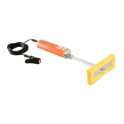
Elcometer 280 T User manual

User Guide
Elcometer 280
Pulsed DC Holiday Detector
en
www.elcometer.com
R

1
Working Safely
2
Gauge Overview
3
Box & Kit Contents
4
Using the Gauge
5
Charging the Battery
6
Fitting the Battery Pack
7
Connecting the Signal Return Lead
8
Getting Started
9
Selecting a Voltage
10
Manually Calculating the Test Voltage
11
The Safety Trigger Switch
12
Detecting a Holiday
13
Probe Accessories
14
Menu Structure - Model S
15
Menu Structure - Model T
16
Maintenance & Storage
17
Warranty Statement
18
Technical Specification
19
Legal Notices & Regulatory Information
en
www.elcometer.com
For the avoidance of doubt, please refer to the original English language version.
The Elcometer 280 is available in 2 models. This User Guide is written for the Model T. Where applicable the
Model S is referenced.
Gauge Dimensions (l x w x h): 60 x 17.3 x 19cm (23.6 x 6.8 x 7.5")
Gauge Weight: 3.0kg (6.6lb) including battery pack
Battery Type: Rechargeable lithium ion battery pack
Operating Temperature: 0°C to 50°C (32°F to 120°F)
Relative Humidity: 0 - 80% up to 31°C (87.8°F)
Pulsed DC High Voltage Range: 0.5 - 35kV, user adjustable in 100V steps & 10V below 1000V
High Voltage Accuracy: ±5% or ±50V below 1000V. Maximum voltage may be reduced at extreme altitudes.
A Material Safety Data Sheet for the Elcometer 280 Battery Pack can be downloaded via our Website:
www.elcometer.com/images/stories/MSDS/elcometer_266_280_battery_pack.pdf
© Elcometer Limited 2011 - 2016. All rights reserved. No part of this document may be reproduced, transmitted,
transcribed, stored (in a retrieval system or otherwise) or translated into any language, in any form or by any
means (electronic, mechanical, magnetic, optical, manual or otherwise) without the prior written permission of
Elcometer Limited.
Hg
CONTENTS
Pb
R
1

1 WORKING SAFELY
en
www.elcometer.com 2
R
The equipment should be used with extreme care.
Follow the instructions given in these Operating
Instructions. Caution - risk of electric shock.
The Elcometer 280 generates a voltage at the probe tip of up to 35,000V.
If the User makes contact with the probe, it is possible to experience a
mild electric shock. Due to the current being very low, this is not normally
dangerous, nevertheless Elcometer does not advise using this product if
you are fitted with a pacemaker.
When in standby the Elcometer 280 will generate radio frequency
emissions which are within the limits defined by the Electromagnetic
Compatibility Directive. Due to its method of operation however, the
Elcometer 280 will generate broadband RF emissions when the unit is
generating high voltage or when a spark is produced at the probe. It is
therefore recommended that the user does not activate the high
voltage, or deliberately generate continuous sparks, within the vicinity
of sensitive electronics or radio equipment.
In order to avoid injury and damage, the following should always be
observed:
û DO NOT use this instrument in hazardous situations and
environments, e.g. an explosive atmosphere, as an
electrical spark indicates detection of a coating flaw.
û DO NOT carry out tests close to moving machinery.
û DO NOT use the instrument in a precarious, unstable or elevated
situation from which a fall may result, unless a suitable
safety harness is used.
û DO NOT use this product if you are fitted with a pacemaker.
û DO NOT allow metallic objects to come into contact with the battery
pack terminals; this may cause a short circuit and result in
permanent damage to the battery.
û DO NOT use this product when it is raining or the unit is wet.
û DO NOT attempt to connect the supply side of the battery charger to
generators or any other medium to high power source other
than the single phase 50/60Hz AC mains outlet supplied
from an approved and safe mains switchboard.
Connection to other supply sources such as generators or
inverters may have the potential to damage the charger, the
battery and/or the gauge invalidating the warranty.

1 WORKING SAFELY (continued)
en
www.elcometer.com
3
R
ü DO read and understand these instructions before using the
equipment.
ü DO charge the battery before the first use of the equipment.
This will take approximately 4 hours.
ü DO consult the plant or safety officer before carrying out
the test procedure.
ü DO undertake testing well clear of other personnel.
ü DO work with an assistant to keep the test area clear and to
help with the testing procedure.
ü DO check that there are no solvents or other ignitable
materials from the coating activities left in the test area,
particularly in confined areas such as tanks.
ü DO switch the instrument off and disconnect the leads when
the work is finished and before leaving it unattended.
ü DO ensure that the earth signal return cable is connected
and extended before you switch on the instrument.
ü DO only use on coatings that are cured, thickness tested and
visually inspected and accepted.
ü DO only use on coatings having a dry film thickness of at
least 200μm (0.008"). For thicknesses between 200μm
and 500μm (0.008” to 0.020”), ensure that an
appropriately low voltage is applied (to prevent damage
to the coating), or use the wet sponge method (using the
Elcometer 270).
ü DO take care when using this product with coatings that are
damp or wet.
ü DO dry the instrument if it gets wet, paying special attention
to the ribbing area.

1 Shoulder Strap Harness Point
2 Sealed, Waterproof Buzzer
3 LCD Display
4 Gauge On/Off Key
5 Voltage Activation Key
6 Multifunction Softkeys
7 Rolling Spring Holder
8 Handgrip
9 LED Indicators - Red (left), Blue (right)
10 Accessory Connection Point
11 Specialised Ribbing (for protection to EN61010)
12 Handle & Integrated Safety Trigger Switch
13 Earth Signal Voltage Return Connection Point
14 Quick Release Rechargeable Battery Pack
www.elcometer.com 4
en
R
2 GAUGE OVERVIEW
2
3
4
5
1
6
9
8
7
10
11
12
14 13

f
Voltage adjustment softkey
g
Sealed, waterproof buzzer
h
Blue LED - flashes when a holiday is detected
i
Holiday detected icon
j
b
Battery symbol indicating remaining charge
k
Voltage selected
l
Standard in use (set via voltage calculator - Model T)
m
Menu softkey (Model T), or buzzer volume softkey (Model S)
n
Voltage level achieved at probe
Elcometer 280 Contents:
<
Pulsed DC Holiday Detector
<
5m (16') trailing signal return lead
<
Rechargeable battery pack & battery charger with mains
cables (UK, EUR & US)
<
Shoulder strap
<
Instruction manual
3 BOX & KIT CONTENTS
en
www.elcometer.com
5
R
Inspection Kit Contents:
All items listed in the Elcometer 280 Contents, plus:
<
Additional rechargeable battery pack (Model T only)
<
Stainless steel rolling spring holder (Model T only)
<
250mm (9.8") probe extension piece
<
Rugged wheeled transit case
a
Red LED -
indicates when high voltage is on
b
Earth signal return lead
disconnected icon
c
Unit overheating icon -
allow unit to cool
d
Porosity detector overload icon ‘ ’
(accessory/coating combination) or
Voltage protection breakdown
a
icon ‘ ’
e
Voltage calculator softkey (Model T),
or Backlight On ‘ ’ /
Off ‘ ’ (Model S)
a Overvoltage output has been prevented; restart test.
b 3 bars: 70 - 100%; 2 bars: 40 - 70%; 1 bar: 20 - 40%; 0 bars: 10 - 20%
Flashing icon & beep every 10 seconds: <10%, re-charge battery
0 bars & 5 loud beeps & auto power off: no charge, recharge required
4 USING THE GAUGE
b
c
d
e
fn
m
l
k
j
i
h
a
g

The Elcometer 280 battery pack is
designed so that it can only be attached in
the correct manner. To connect the battery
pack:
1 Turn the gauge onto its side.
2 Push the battery pack into the battery
housing.
3 Tighten up the two battery pack
retaining screws (a).
To remove the battery pack, unscrew the two battery pack retaining
screws (a) at the rear of the instrument and slide out the battery pack.
5 CHARGING THE BATTERY
Upon receiving the Elcometer 280, the rechargeable battery supplied
has a small amount of charge (for safety reasons) and should be fully
charged before using the instrument for the first time.
Use only the charger supplied with your instrument to charge the
battery.
Use of any other type of charger is a potential hazard, may damage
your instrument and will invalidate the warranty.
Do not attempt to charge any other batteries with the supplied charger.
Always charge the battery indoors.
To prevent overheating, ensure that the charger is not covered.
Each re-chargeable battery can be recharged in approximately 4
hours.
1 Connect the lead from the charger into
the socket on the battery.
2 Plug the charger supplied into the
mains supply. The LED indicator on the
charger will glow orange.
3 Leave the gauge charging for at least 4 hours. The LED indicator
changes colour from orange to green when charging is complete.
4 When charging is complete, disconnect the charger from the
mains supply before removing the lead from the instrument.
www.elcometer.com 6
en
R
6 FITTING THE BATTERY PACK
a

1 Ensure that the Elcometer 280 is off.
2 Insert the signal return lead plug into
the socket.
3 Push the plug in and twist it ¼ turn to
the right.
4 Switch the gauge on.
5 Make sure the signal return lead is
uncoiled and extended. For the most
ideal conditions, attach the signal
return lead to an uncoated area of the
substrate, using part number
T28022750.
6 If ‘ ’ icon is displayed, the plug is not
connected correctly, repeat steps 1-5.
If problem persists, please contact your Elcometer distributor.
To remove the lead, push the plug in and twist it ¼ turn to the left.
7 CONNECTING THE SIGNAL RETURN LEAD
en
www.elcometer.com
7
R
8 GETTING STARTED
1 Press the ON/OFF button until the
Elcometer logo is displayed. é
2 Select your language using the
ê
softkeys (Model T only) and press the
OK softkey.
If ‘ ’ icon is displayed, the return lead
plug may not be connected, see Section 7.
To access the language menu when in an
alternate language:
1 Switch the gauge OFF.
2 Press and hold the left softkey and
switch the gauge ON. é
3 Select your language using the
ê
softkeys.
www.elcometer.com
1
2

9 SELECTING A VOLTAGE
www.elcometer.com 8
en
R
The voltage of the Elcometer 280 can either
be set automatically using the gauge’s internal
voltage calculator (Model T) or adjusted
manually (Models S & T).
Adjusting the voltage manually
1 Switch the gauge ON.
2 Press the ‘Volt’ softkey.
é
3 Using the softkeys, adjust the
ê
voltage to the required level.
4 Press OK.
The selected voltage appears above the kV
symbol ('5.00' in the example images).
To determine the correct voltage to use see
‘Calculating the test voltage’ on page 9.
Setting the voltage using the Voltage Calculator
The voltage calculator function within the
Elcometer 280 Model T gauge is designed to
automatically calculate the test voltage
according to a user selected test standard and
the dry film thickness of the test sample.
1 Switch the gauge ON.
2 Press the ‘Calc’ softkey. The gauge will
display the standard currently selected.
To change the standard:
i Press the ‘Std’ softkey.
é
ii Using the softkeys, select the
ê
relevant test standard.
iii Press OK.
3 If the standard currently selected is
correct, press OK.
é
4 Using the softkeys adjust the dry film
ê
thickness to the required value and press
c
OK .
Elcometer 280
Model S
Elcometer 280
Model T
c The Set Thickness Screen will show the last used coating thickness and the upper and lower thickness
values for the selected test standard.

9 SELECTING A VOLTAGE (continued)
5 A confirmation screen will now display the
selected test standard, dry film thickness
and calculated test voltage,
i Press OK to set the instrument voltage
to the calculated value,
or
ii Press ESC to return to the reading
screen without making changes.
en
www.elcometer.com
9
R
10 MANUALLY CALCULATING THE TEST VOLTAGE
When setting the voltage manually please follow the guidelines below
which describe how a safe, but effective, test voltage may be
determined.
Overview
For effective testing, the test voltage must lie between two limits - the
upper and lower limits.
The upper voltage limit is that at which the coating itself would
breakdown and be damaged at the thickness applied.
The lower limit is the voltage required to break down the thickness of
air equivalent to the coating thickness. If the output voltage is not
greater than this value, then a flaw will not be detected.
These two limits can be determined and a voltage approximately half
way between them selected as the test voltage.
Dielectric Strength
Whatever the material, if a high enough voltage is applied, it will
conduct electricity. For insulators such as paint, however, the level of
voltage required to achieve a current flow usually results in
irreversible material damage.

10 MANUALLY CALCULATING THE TEST VOLTAGE (continued)
www.elcometer.com 10
en
R
The voltage at which a particular thickness of material breaks down is
termed the dielectric strength. This is usually expressed as the
voltage per unit distance, e.g. kV/mm (kV/inch). Its value depends on
the type of applied voltage (AC, DC or pulsed), temperature and
thickness.
The dielectric strength of coating materials usually lies in the region
of 10 kV/mm to 30 kV/mm (250kV/inch to 750kV/inch). The dielectric
strength of air ranges from 1.3 kV/mm to 4 kV/mm (33kV/inch to
100kV/inch).
Establishing the lower voltage limit
The lower limit for effective operation is that required to breakdown
the thickness of air equivalent to the coating thickness. The
breakdown voltage of a given thickness of air varies with humidity,
pressure and temperature.
If the coating thickness is known, or can be measured, the lower
limit value can be determined from the breakdown voltage for air at
that dry film thickness.
If the coating thickness is not known then the minimum value has to
be established experimentally. Reduce the voltage setting to minimum
and position the probe over an unprotected area of substrate at the
normal height of the coating surface. Increase the voltage slowly and
steadily until a spark is produced. Make a note of this voltage - it is the
lower voltage limit.
Establishing the upper voltage limit
The upper voltage limit may be determined by:
The job specification - if available and a test voltage is stated.
The dielectric strength - if specified for the applied coating.
Measure the thickness of the layer and determine the voltage by
multiplying the dry film thickness by the dielectric strength.

In order to minimise the possibility of accidentally switching the voltage
on, the Elcometer 280 is fitted with both a safety trigger switch (a) and
a voltage activation key (b).
The voltage will only be activated when:
1 The gauge is switched ON.
2 The safety trigger switch (a) is held, and
3 The voltage activation key (b) is pressed.
4 The signal return lead is fitted.
If the safety trigger switch is released when the
gauge is in operation, the voltage is
immediately disconnected.
If the safety trigger switch is held again within 3
seconds, the voltage will automatically re-
activate (without the need to press the voltage
activation key).
10 MANUALLY CALCULATING THE TEST VOLTAGE (continued)
For example:
Metric: if you have 500 microns of coating (0.5mm) with a
dielectric strength of 6kV/mm, the upper voltage
will be 3kV.
Imperial: if you have 20 mils of coating (0.02inch) with a
dielectric strength of 150kV/inch, the upper voltage
would be 3kV.
Experiment
Touch the probe on an unimportant area of the work piece. Increase
the voltage slowly and steadily until a spark passes through the
coating. Make a note of this voltage - it is the upper voltage limit.
Note: The dielectric strength can be calculated by dividing this voltage by the
coating thickness.
Tables and formulae
Alternatively, the correct voltage levels can be determined from
established Codes of Practice, e.g. NACE and ASTM.
en
www.elcometer.com
11
R
11 THE SAFETY TRIGGER SWITCH
a
b

12 DETECTING A HOLIDAY
The Elcometer 280 identifies the detection of a holiday in the following
manner:
1 The blue LED flashes;
2 The buzzer alarms;
3 The holiday detection ‘ ’ icon is displayed;
4 The backlight and display flashes;
5 A spark is generated.
www.elcometer.com 12
en
R
13 PROBE ACCESSORIES
The Elcometer 280 Pulsed DC Holiday detector has a wide range of
electrodes available for testing a variety of structures and forms, these
include:
Ÿ Wire brush probes
Ÿ Internal pipe brush probes
Ÿ External ‘c-type’ brush probes
Ÿ External pipe rolling springs
Ÿ Conductive rubber probes
Ÿ Grounding mats - ideal for testing ungrounded coated structures
Ÿ Accessory adaptors - allowing the Elcometer 280 to work with
electrodes from other manufacturers
For more information on probe accessories for the Elcometer 280
please visit the Elcometer website or contact your nearest distributor.
14 MENU STRUCTURE - MODEL S
Set Test Voltage
XX.x kV
Esc V+ V- Ok
X
Beep Volume : 3
Esc + - Ok

15 MENU STRUCTURE - MODEL T
Voltage Calculator
Standard Selected:
(Name of Standard)
Esc Std Ok
Set Test Voltage
XX.x kV
Esc V+ V- Ok
Menu
Backlight
Beep Volume
Setup
About
Reset
Back Sel
○
3
Reset
Metric Gauge
Imperial Gauge
Back Sel
About
Gauge Information
Contact Information
Back Sel
Setup
Units
Language
Auto Switch Off †
Voltage Warning ON
Back Sel
15
○
† Can be used when operating at low voltages to emit a ‘ticking’ sound indicating that a voltage is being produced.
Select Standard
AS3894.1:F1 2002
AS3894.1:F2 2002
AS3894.1:F3 2002
AS3894.1:F4 2002
ASTM D4787-08
ASTM D5162-08
AWWA C203-08
ISO 29601-2011
NACE RP0274-2004
NACE SP0188-2006
NACE SP0490-2007
Back Ok
en
www.elcometer.com
13
R
16 MAINTENANCE & STORAGE
The Elcometer 280 has a liquid crystal display (LCD). If the LCD is
heated above 50°C (120°F) it may be damaged. This can happen if the
instrument is left in a vehicle which is parked in strong sunlight.
To ensure the Elcometer 280 remains in good working order, keep the
instrument, connecting cables and probe electrodes clean. Before
cleaning, switch the instrument OFF and remove the battery and all
cables.
To clean, wipe surfaces with a damp cloth and then allow sufficient
time to air dry all components before use. Do not use any solvents to
clean the instrument.
From time to time inspect the instrument and accessories for damage
and replace or return the unit to Elcometer for repair.
Note: With the exception of probe electrodes and cables, the instrument does not
have any components which can be serviced by the user. Please return
the instrument to Elcometer for service.

17 WARRANTY STATEMENT
One year as standard. To extend the warranty to 2 years free of
charge, register your gauge online within 60 days from date of
purchase at www.elcometer.com.
18 TECHNICAL SPECIFICATION
www.elcometer.com 14
en
R
Pulsed DC High
Voltage Range
0.5kV - 35kV
Voltage
Adjustment
User adjustable:
0.5 - 1kV: 10 Volt steps,
1 - 35kV: 100V steps
High Voltage
Output Accuracy
±5% or ±50V below 1000 Volts
Pulse Repetition
Rate
~30Hz
Operating
Temperature
0°C to 50°C (32°F to 120°F)
Power Supply
Rechargeable lithium ion battery,
fully charged within 4 hours
Typical Battery
Life
Battery life is dependant on selected voltage and load
applied;
12" (DN305) Rolling Spring:
30 hours at 10kV;
12 hours at 35kV
40" (DN1016) Rolling Spring:
22 hours at 10kV;
8 hours at 35kV
Instrument Case
Dimensions
PC ABS case; (l x w x h):
603 x 219 x 193mm (23.7 x 8.6 x 7.6”)
Weight
(no probes attached)
3.0kg (6.6lb) - including battery pack
Can be used in accordance with:
AS 3894.1, ANSI/AWWA C203, ANSI/AWWA C214, ASTM D4787,
ASTM D5162, ISO 29601, JIS G 3491, JIS G 3492, NACE RP0274,
NACE SP0188, NACE SP0490, NACE TM0186, NACE TM0384.

en
R
19 LEGAL NOTICES & REGULATORY INFORMATION
The Elcometer 280 Models S and T, in standby, meet the Electromagnetic Compatibility
Directive and the Low Voltage Directive. The product is Class A, Group 1 ISM equipment
according to CISPR 11. Group 1 ISM product: A product in which there is intentionally
generated and/or used conductively coupled radio-frequency energy which is necessary for
the internal functioning of the equipment itself. Class A products are suitable for use in all
establishments other than domestic and those directly connected to a low voltage power
supply network which supplies buildings used for domestic purposes.
Note: Additional information is given in “Working safely” on page 2.
Product Description: Elcometer 280 Pulsed DC Holiday Detector
Manufactured by: Elcometer Limited, Manchester, England
is a registered trademark of Elcometer Limited, Edge Lane, Manchester,
M43 6BU. United Kingdom
All other trademarks acknowledged.
R
TMA-0495 Issue 05 - Text with cover 22881

Guide d'utilisation
Elcometer 280
Porosimètre à Impulsion DC
fr
www.elcometer.com
R

1
Travailler en toute sécurité
2
Présentation de l'instrument
3
Liste de colisage valise et kit
4
Utiliser l'instrument
5
Charger la batterie
6
Installer la batterie
7
Connecter le câble de mise à la terre
8
Premières démarches
9
Sélectionner une tension
10
Calculer manuellement la tension de test
11
Gâchette de sécurité
12
Détecter un défaut
13
Accessoires de sonde
14
Structure Menu – Modèle S
15
Structure Menu – Modèle T
16
Maintenance & Stockage
17
Déclaration de garantie
18
Caractéristiques techniques
19
Informations légales & règlementaires
www.elcometer.com
En cas de doute, merci de vous référer à la version originale anglaise de ce manuel.
L'Elcometer 280 est disponible en deux versions. Ce manuel est rédigé pour le modèle T. Le modèle S est
référencé lorsque cela est approprié.
Dimensions de l'instrument (L x l x h): 60 x 17.3 x 19 cm (23.6 x 6.8 x 7.5")
Poids de l'instrument : 3.0 Kg (6.6lb) avec la batterie
Type de batterie : batterie ion lithium rechargeable
Température de travail : 0° C à 50° C (32°F à 120°F)
Humidité Relative : 0 - 80% jusqu'à 31° C (87.8°F)
Plage Haute Tension Pulsée DC : 0.5 - 35kV, réglable par pas de 100V & 10V en-dessous de 1000 V
Précision Haute Tension : ±5% ou ±50V en-dessous de 1000V. La tension maxi peut être réduite à des altitudes
extrêmes.
Une fiche de données de sécurité pour le pack de batteries de l'Elcometer 280 peut être téléchargé sur notre sit:
www.elcometer.com/images/stories/MSDS/elcometer_266_280_battery_pack.pdf
© Elcometer Limited 2011 - 2016. Tous droits réservés. Aucune partie de ce document ne peut être reproduite,
transmise, transcrite, stockée (dans un système documentaire ou autre) ou traduite dans quelque langue que
ce soit, sous quelque forme que ce soit ou par n'importe quel moyen (électronique, mécanique, magnétique,
optique, manuel ou autre) sans la permission écrite préalable d’Elcometer Limited.
Hg
SOMMAIRE
Pb
R
1
fr

1 TRAVAILLER EN TOUTE SÉCURITÉ
www.elcometer.com 2
R
Cet équipement doit être utilisé avec précaution. Merci de
suivre les instructions mentionnées dans ce Manuel.
Attention - risque de choc électrique.
L'Elcometer 280 génère une tension à l'extrémité de la sonde pouvant
atteindre 35'000 V. Si l'utilisateur touche la sonde, il peut ressentir un
léger choc électrique. L'intensité du courant étant très faible, ce n'est
généralement pas dangereux. Cependant, Elcometer déconseille
l'utilisation de cet instrument aux porteurs de Pacemakers.
Les émissions radioélectriques générées par l'Elcometer 280 en mode
veille sont dans les limites définies par la Directive Electromagnétique.
Cependant, en raison de son principe de fonctionnement, l'Elcometer
280 génère des ondes radio à haut débit lorsque la sonde est sous
tension ou qu'elle produit une étincelle. Il faut donc éviter d'activer la
haute tension ou de générer délibérément une étincelle à proximité
d'équipements électroniques ou radio sensibles.
Pour éviter tout risque de blessure ou de dégât, appliquez toujours les
consignes suivantes :
û NE PAS utiliser l'instrument dans une situation ou un environnement
dangereux, comme une atmosphère explosive, car une
étincelle se produit quand un défaut est détecté.
û NE PAS réaliser des tests à proximité de machines en mouvement.
û NE PAS utiliser l'appareil en équilibre précaire, en hauteur, en
raison du risque de chute, à moins d'être équipé d'un
harnais de sécurité approprié.
û NE PAS utiliser cet appareil si vous avez un Pacemaker.
û NE PAS toucher les cosses de la batterie avec un objet métallique
à cause du risque de court-circuit qui pourrait
endommager irréversiblement la batterie.
û NE PAS utiliser l'instrument quand il pleut ou lorsque l'appareil est
mouillé.
û NE PAS tenter de brancher l'alimentation du chargeur sur un
générateur ou tout type d'alimentation autre que le
courant monophasé 50/60Hz AC provenant d'un réseau
approuvé et sécurisé.
Un branchement sur toute autre source d'alimentation,
comme des générateurs ou des onduleurs, pourrait
endommager le chargeur, la batterie et/ou annuler la
fr

1 TRAVAILLER EN TOUTE SÉCURITÉ (suite)
www.elcometer.com
3
R
ü TOUJOURS lire et comprendre ces instructions avant d'utiliser
l'appareil.
ü TOUJOURS charger la batterie avant la première utilisation. Cela
demande environ 4 heures.
ü TOUJOURS consulter le (la) Responsable de l'usine ou de la
sécurité avant de réaliser des contrôles.
ü TOUJOURS procéder aux contrôles à l'écart d'autres personnes.
ü TOUJOURS travailler avec un assistant pour dégager la zone de
contrôle et vous aider pendant la procédure.
ü TOUJOURS vérifier qu'il ne reste aucun solvant ou matériau
inflammable (utilisé pour les travaux de revêtement),
en particulier dans les endroits confinés tels que les
réservoirs.
ü TOUJOURS éteindre l'instrument et débrancher les câbles une
fois le travail terminé, et avant de le laisser sans
surveillance.
ü TOUJOURS vérifier que le câble de terre est déroulé et connecté
avant d'allumer l'appareil.
ü TOUJOURS utiliser l'appareil sur des revêtements secs, dont
l'épaisseur a été mesurée, et qui ont été visuellement
inspectés et acceptés.
ü TOUJOURS utiliser sur des revêtements d'une épaisseur
minimale de 200 µm (0.008''). Pour des épaisseurs
comprises entre 200 μm et 500 μm (0.008” et
0.020”), vérifier que la tension appliquée est
suffisamment basse (pour éviter d'endommager le
revêtement), ou utiliser la méthode de l'éponge
humide (avec l'Elcometer 270).
ü TOUJOURS procéder avec prudence sur des revêtements
humides ou mouillés.
ü TOUJOURS sécher l'appareil s'il se mouille, en particulier sur la
partie crantée.
fr
This manual suits for next models
1
Table of contents
Languages:
Other Elcometer Security Sensor manuals
