Elcometer 266 User manual

User Guide
Elcometer 266
DC Holiday Detector
www.elcometer.com
R

1
Working Safely
2
Gauge Overview
3
Box Contents
4
Using the Gauge
5
Getting Started
6
High Voltage Probe Handle
7
Preparing for Test
8
Test Procedure
9
Setting the Probe Handle Voltage
10
Setting the Sensitivity
11
Static Electricity
12
Probe Accessory Selection
13
The Second Hand Grip
14
Special Considerations
15
Error Messages
16
Spares & Accessories
17
Warranty Statement
18
Technical Specification
19
Care & Maintenance
20
Legal Notices & Regulatory Information
21
Appendix A: Standards
22
Appendix B: Calculating The Correct Test Voltage
For the avoidance of doubt, please refer to the original English language version.
Kit Dimensions: 520 x 370 x 125mm (20.5 x 14.5 x 5”)
Weight: Base Unit (including battery pack): 1.2kg (2.7lb); Handle: 0.6kg (1.3lb)
Base Unit, Handle & Connecting Cable: 2kg (4.4lb)
A Material Safety Data Sheet for the Elcometer 266 Battery Pack is available to download via our website:
http://www.elcometer.com/images/stories/MSDS/elcometer_266_280_battery_pack.pdf
© Elcometer Limited 2010-2016. All rights reserved. No part of this document may be reproduced, transmitted,
transcribed, stored (in a retrieval system or otherwise) or translated into any language, in any form or by any
means (electronic, mechanical, magnetic, optical, manual or otherwise) without the prior written permission of
Elcometer Limited.
CONTENTS
www.elcometer.com
en-1
R

www.elcometer.com en-2
R
1 WORKING SAFELY
The equipment should be used with extreme care.
Follow the instructions given in this user guide.
Caution - risk of electric shock.
The high voltage handle generates a voltage at the probe tip of up to
30 000 V. If the user makes contact with the probe, it is possible to
experience a mild electric shock. Due to the current being very low,
this is not normally dangerous, nevertheless Elcometer does not
advise using this product if you are fitted with a pacemaker.
An electrical spark indicates detection of a coating flaw; do not use
this instrument in hazardous situations and environments, e.g. an
explosive atmosphere.
Due to its method of operation, the Elcometer 266 will generate broad
band RF emissions when a spark is produced at the probe, i.e., when
a flaw in the coating is located. These emissions may interfere with
the operation of sensitive electronic apparatus in the vicinity. In the
extreme case of a continuous spark of length 5mm, the magnitude of
emissions at a distance of 3m was found to be approximately
60 dBµV/m from 30 MHz to 1000 MHz. It is therefore recommended
that this equipment is not operated within 30m of known sensitive
electronic equipment and that the user does not deliberately generate
continuous sparks.
In order to avoid injury and damage, the following should always be
observed:
DO NOT use this instrument in hazardous situations and
environments, e.g. any combustible, flammable or other
atmosphere where an arc or spark may result in an
explosion.
DO NOT carry out tests close to moving machinery.
DO NOT use the instrument in a precarious, unstable or elevated
situation from which a fall may result, unless a suitable
safety harness is used.
DO NOT use this product if you are fitted with a pacemaker.
DO NOT use this product when it is raining, in a damp atmosphere
or if the unit is wet.

www.elcometer.com
en-3
R
1 WORKING SAFELY (continued)
DO read and understand these instructions before using the
equipment.
DO charge the battery before the first use of the equipment.
This will take approximately 4 hours, see Section 5.1
‘ ging the Battery Pack’ on page en-7.Char
DO consult the plant or safety officer before carrying out
the test procedure.
DO undertake testing well clear of other personnel.
DO work with an assistant to keep the test area clear and to
help with the testing procedure.
DO check that there are no solvents or other ignitable
materials from the coating activities left in the test area,
particularly in confined areas such as tanks.
DO switch the instrument off and disconnect the leads when
the work is finished and before leaving it unattended.
DO ensure that the earth signal return cable is connected
and extended before you switch on the instrument.
DO only use on coatings that are cured, thickness tested and
visually inspected and accepted.
DO only use on coatings having a dry film thickness of at
least 200μm (0.008"). For thicknesses between 200μm
and 500μm (0.008” to 0.020”), ensure that an
appropriately low voltage is applied (to prevent damage
to the coating), or use the wet sponge method (using the
Elcometer 270).
DO bond the work piece to a ground potential to minimise the
potential for build up of static charge, see Section 11
‘Static Electricity’ on page en-21.
DO take care when using this product with coatings that are
damp or wet.
DO dry the instrument if it gets wet, paying special attention
to the ribbing area.

2 GAUGE OVERVIEW
The Elcometer 266 detects flaws in protective coatings up to 7mm
(25mils) thick and is ideal for inspecting coatings on pipelines and
other protective coatings.
The coating under test can be electrically non-conductive or partially
conductive (such as coatings which contain metallic or carbon
particles). The coating must be at least 200µm (0.008") thick, and
preferably over 500µm (0.020"), thick.
The underlying substrate must be an electrically conductive material
such as metal or concrete (concrete is reasonably conductive because
of its water content).
Typical flaws are pinholes (a very narrow hole running from the
coating surface to the substrate), holidays (small uncoated areas),
inclusions (objects trapped in the coating, e.g. grit from blast cleaning),
air bubbles, cracks and thin spots.
The Elcometer 266 probe handle generates a high DC voltage which
is applied to the surface of the coating via a probe. An earth signal
return cable is connected between the instrument and the substrate.
When the probe is passed over a coating flaw, the electrical circuit is
completed and current flows from the probe to the substrate. As a
result, the instrument gives audible and visual alarms and a spark may
be produced at the flaw.
The user can perform the test to any one of a number of international
testing standards using the built-in Voltage Calculator.
The Elcometer 266 features an easy to use menu-driven graphical
interface which guides the user during setup of the instrument and
during measurement.
The instrument will operate in one of three voltage ranges; 0.5 kV to 5 kV,
0.5 kV to 15 kV and 0.5 kV to 30 kV. The voltage range is determined by
the model of high voltage probe handle fitted to the instrument - not the
instrument itself.
www.elcometer.com en-4
R

2 GAUGE OVERVIEW (continued)
Elcometer 266 DC Holiday Detector
Earth Signal Return Lead, 10m (32 ft)
Connecting Cable for High Voltage Probe Handlea
Band Brush Probe
Rechargeable Lithium-ion Battery Pack
Battery Charger (UK, EU, US and AUS plugs included)
Shoulder Strap
Transit Case
Calibration Certificate (if ordered)
User Guide
a High voltage probe handle must be ordered separately - see Section 6 ‘High Voltage Probe Handle’
on page en-11.
3 BOX CONTENTS
www.elcometer.com
en-5
R
2
1
8
9
10
5
3
3
6
7
4
1 On/Off Key
2 Multi Function Menu Keys
3 Shoulder Strap Connection
4 Rechargeable Lithium-ion Battery Pack
5 LCD Display
6 High Voltage Probe Handle Connection
7 Earth Signal Return Cable Connection
8 High Voltage Probe Handle Connecting Cable
9 High Voltage Probe Handle
10 Probe Accessory Connection

a
b
c
d
e
fg
h
i
j
k
4 USING THE GAUGE
4.1 THE CONTROLS
The Elcometer 266 is operated using the keypad on the instrument
and the button on the high voltage probe handle.
1 Scroll up / down through menus and lists of values
Increases / Decreases Values
2 The function of these keys varies and is shown on the display
3 Switches the instrument on / off
4 Press to toggle high voltage probe handle on / off
5 Red light: Probe voltage is on
6 Blue light: Flaw detected
4.2 THE DISPLAY
The main screen displayed (whilst taking measurements) is the
Reading Screen.
www.elcometer.com en-6
R
a
Current: Measured Value
b
Current: Set Value
c
Voltage: Measured Value
d
Voltage: Set Value
e
Calculate Voltage
f
Adjust Voltage
g
Adjust Sensitivity
h
View Menu
i
Voltage Locked (see page en-11)
j
Sensitivity Locked (see page en-11)
k
Battery Life Indicator
R
2
3
1
R
kV
4
5
6

5.1 CHARGING THE BATTERY PACK
The Elcometer 266 is powered by a rechargeable Lithium- b
Ion battery
pack which can be charged inside or outside the instrument.
Each instrument is dispatched from the factory with the battery
discharged. Recharge the battery fully before using for the first time.
Note: Only one battery pack is supplied with each instrument. To increase productivity
on site, we recommend purchasing a spare battery pack which can be charged
whilst the instrument is in use, see Section 16.3 ‘ Batteries, Chargers & Earth
Signal Return Leads’ on page en-28.
Before you start:
Use only the charger supplied with the Elcometer 266 to charge
the battery. Use of any other type of charger is a potential
hazard, may damage your instrument and will invalidate the
warranty. Do not attempt to charge any other batteries with the
supplied charger.
Always charge the battery indoors.
To prevent overheating, ensure that the charger is not covered.
The instrument can be charged whilst it is switched on or off. If
charged whilst switched on, the high voltage supply to the probe
will be disconnected automatically and a battery charging icon will
be shown on the display. If charged whilst switched off, the
display will remain blank.
WARNING: Do not attempt to connect the supply side of the battery charger to
generators or any other medium to high power source other than the single
phase 50Hz A.C. mains outlet supplied from an approved and safe mains
switchboard. Connection to other supply sources such as generators or
inverters may have the potential to damage the charger, the battery and/or the
instrument invalidating the warranty.
Charging the battery pack inside the instrument:
1 Unscrew the retaining screw (a)
and open the access cover on the
rear of the instrument.
2 Connect the lead from the charger
into the socket marked ‘Charger
Input’ behind the interface access
cover.
5 GETTING STARTED
b The Elcometer 266 is not designed to operate using dry cell batteries.
a
www.elcometer.com
en-7
R

5 GETTING STARTED (continued)
3 Plug the charger supplied into the mains supply. The LED
indicator on the charger will glow orange.
4 Leave the gauge charging for at least 4 hours. The LED indicator
changes colour from orange to green when charging is complete.
5 When charging is complete, disconnect the charger from the
mains supply before removing the lead from the instrument.
Charging the battery pack outside the instrument:
1 Unscrew the two battery pack
retaining screws at the rear of the
instrument and slide out the battery
pack.
2 Connect the lead from the charger into
the socket on the battery pack.
3 Plug the charger supplied into the
mains supply. The LED indicator on
the charger will glow orange.
4 Leave the battery pack charging for at least 4 hours. The LED
indicator changes colour from orange to green when charging is
complete.
5 When charging is complete, disconnect the charger from the
mains supply before removing the lead from the battery pack.
Whilst the battery pack is removed from the instrument, do not allow metallic
objects to come into contact with the battery terminals; this may cause a short
circuit and result in permanent damage to the battery.
The battery condition is indicated by a symbol on the display:
Symbol
Battery Charge / Action Required
70% to 100%
40% to 70%
20% to 40%
10% to 20% - charging recommended
<10%, instrument beeps every 10 seconds and symbol ashes -
immediate charging required
5 loud beeps, instrument switches off automatically
www.elcometer.com en-8
R

5.2 SWITCHING THE INSTRUMENT ON / OFF
To switch on/off: Press the On/Off button ‘ ’.
Note: To extend battery life (time between charges) the instrument can be set to
switch off automatically after a user defined period of inactivity between 1 and
15 minutes. The default setting is 15 minutes.
5.3 SELECTING YOUR LANGUAGE
1 Press the MENU key to display the main menu.
When the instrument is switched on for the first time after despatch from the
Elcometer factory, the language selection screen will be displayed. Proceed
to Step 2.
2 Select your language using the keys.
3 Press SEL to activate the selected language.
To access the language menu when in a foreign language:
1 Switch the instrument OFF.
2 Press and hold the left hand key and switch the instrument ON.
The display will show the language selection screen with the
current language highlighted by the cursor.
3 Select your language using the keys.
4 Press SEL to activate the selected language.
5.4 CONFIGURING THE INSTRUMENT
1 Press the MENU key to display the main menu.
2 Use the keys to scroll up and down the menu items.
3 Press SEL to activate the selected option or access the sub-
menu, see Table 1.
4 Press BACK or ESC to leave the main menu or any sub-menu.
TABLE 1
Option
Action Required
BACKLIGHT
Press SEL to toggle the display backlight on or off.
BEEP VOLUME
Press SEL followed by or to set the beep volume;
1 (minimum) to 5 (maximum). Press OK when finished.
UNITS
Press SEL followed by or to select the measurement
units;µm, mm, mil, thou or inch. Press OK when nished.
LANGUAGES
Press SEL followed by or to select the display language.
Press OK when finished.
5 GETTING STARTED (continued)
www.elcometer.com
en-9
R

5 GETTING STARTED (continued)
TABLE 1
Option
Action Required
ABOUT
Press SEL to view the ABOUT menu.
RESET
Press SEL to view the RESET menu
AUTO SWITCH
OFF
Press SEL followed by + or - to set the auto switch off delay; 1
to 15 minutes or off (X). Press OK when nished.
OPENING
SCREEN
Press SEL to toggle the opening screen on or off.
VOLTAGE
LOCKED
Press SEL to toggle the voltage lock on or off, see Section 5.6
‘Voltage and Sensitivity Locks’ on page en-11.
SENSITIVITY
LOCKED
Press SEL to toggle the sensitivity (current) lock on or off, see
Section 5.6 ‘Voltage and Sensitivity Locks’ on page en-11.
www.elcometer.com en-10
R
5.5 CLICKS, BEEPS, ALARMS AND LIGHTS
The Elcometer 266 emits a range of sounds and lights whilst in use,
see Table 2 below.
TABLE 2
Sound
Lights
Indicates
Single beep -
high pitch
Red light on high voltage
probe handle illuminates
High voltage to probe is
switched on
Double beep -
high pitch
Red light on high voltage
probe handle ashes on/off
The safety interlock on the
high voltage probe handle
is not being gripped by your
hand
Clicks - continuous
series of
Red light on high voltage
probe handle is illuminated
High voltage is present at
the probe
Alarm buzzing
Blue light on high voltage
probe handle ashes on/off
Flaw detected

www.elcometer.com
en-11
R
5 GETTING STARTED (continued)
5.6 VOLTAGE AND SENSITIVITY LOCKS
The voltage and sensitivity settings on the Elcometer 266 include a
‘lock’ feature which helps to prevent accidental changes to these
values once they have been set.
The voltage lock can be toggled on or off from the main menu,
see Section 5.4 ‘Configuring the Instrument’ on page en-9. The
voltage lock also switches on automatically once the voltage has
been set using CALC.
The sensitivity lock can be toggled on or off from the main menu,
see Section 5.4 ‘Configuring the Instrument’ on page en-9.
If a voltage or sensitivity lock is switched on, it can be overidden during
setting of the value by pressing the UNLOCK key. The lock will re-
engage automatically once the value has been set.
6 HIGH VOLTAGE PROBE HANDLE
A range of interchangeable high voltage probe
handles is available for the Elcometer 266. A label
on the underside of the handle indicates the
maximum working voltage of the handle
(5 kV, 15 kV or 30 kV).
The choice of which high voltage probe handle to use depends upon
the maximum test voltage required, which in turn depends upon the
thickness of the coating being tested and the recommendations of any
test standard which may be being followed.
The Elcometer 266 is not supplied with a probe handle, these must be
ordered separately.
Description Voltage Part Number
Elcometer 266 Probe Handle, DC5 0.5 - 5 kV T26620033-1
Elcometer 266 Probe Handle, DC15 0.5 - 15 kV T26620033-2
Elcometer 266 Probe Handle, DC30 0.5 - 30 kV T26620033-3
Elcometer 266 Probe Handle, DC30S 0.5 - 30 kV T26620033-4
(Continuous Voltage)
Note: The DC30S Continuous Voltage Probe Handle is compatible with Elcometer 266
instruments with serial numbers ‘SC16119’ onwards. The software in older
instruments must be updated by Elcometer or your local Elcometer distributor to
recognise the new DC30S handle.

6.1 CONNECTING A HIGH VOLTAGE PROBE HANDLE
The instrument must be switched off when a high voltage probe handle
is fitted or removed.
Connect the high voltage probe handle to the instrument using the
supplied connecting cable (the grey curly cable). The connecting
cable is fitted with a metal screw-type connector at each end. To fit a
connector, align the keyway, push the connector into place and then
tighten the metal collar.
If the instrument is switched on without a high
voltage handle fitted a warning message is
displayed.
6.2 HIGH VOLTAGE PROBE HANDLE SAFETY INTERLOCK
All high voltage probe handles (with the exception of the DC30S
Continuous Voltage Probe Handle, see Section 6.3 on page en-13) are
fitted with a safety interlock device.
The safety interlock is fitted inside the
black rubberised grip on the underside
of the high voltage probe handle.
When this section of the handle is held
by the hand as shown, the interlock
switch is released and the voltage to
the probe can be switched on (by
pressing the button on the handle).
If the grip is released whilst the probe is
at high voltage:
the voltage at the probe will drop to zero immediately,
the instrument will emit a high pitched beep, and
the red light on the handle will flash.
www.elcometer.com en-12
R
6 HIGH VOLTAGE PROBE HANDLE (continued)

www.elcometer.com
en-13
R
6 HIGH VOLTAGE PROBE HANDLE (continued)
If the grip is then grasped again within approximately two seconds the
voltage at the probe will be immediately restored. This feature allows
the user to adjust their grip as required without interruption.
If the grip is not grasped within this two second interval, the high
voltage probe handle is switched off automatically. To continue testing,
grasp the handle again and press the button on the handle.
6.3 DC30S CONTINUOUS VOLTAGE PROBE HANDLE
The DC30S probe handle does not have
the safety interlock feature.
To switch off the voltage output, press the
On/Off key (a) on the top of the handle.
Alternatively, switch off the Elcometer 266
instrument using the On/Off key (b).
To connect the handle to the instrument,
follow the instructions outlined in Section
6.1 ‘Connecting a High Voltage Probe
Handle’ on page en-12.
When a DC30S probe handle is connected
to the instrument, a warning message is
displayed each time the instrument is
switched on. Press OK to acknowledge
and continue operating as normal.
Note: The DC30S Continuous Voltage Probe
Handle is compatible with Elcometer 266
instruments with serial numbers ‘SC16119’
onwards. The software in older instruments
must be updated by Elcometer or your local
Elcometer distributor to recognise the new
DC30S handle.
a
R
b

7 PREPARING FOR TEST
www.elcometer.com en-14
R
Please read the information in Section 1 ‘Working Safely’ on
page en-2 before using the equipment. If in doubt, contact
Elcometer or your local Elcometer supplier.
7.1 CONNECT THE CABLES
1 Connect the high voltage probe handle to the instrument using
the grey curly cable (Figure 1).
2 Connect the clamp of the earth signal return cable to an exposed
section of substrate. Plug the other end of the cable into the
instrument (Figure 2).
R
R
Figure 1 Figure 2
7.2 FIT THE PROBE ACCESSORY
Select the probe accessory best suited for the work being undertaken,
see Section 12 ‘Probe Accessory Selection’ on page en-22, and attach
it to the high voltage probe handle (Figure 3).
R
Figure 3

www.elcometer.com
en-15
R
7 PREPARING FOR TEST (continued)
7.3 CHECK THE CABLE CONNECTIONS
1 Press the On/Off button to switch the instrument on.
2 Reduce the voltage setting to the minimum value, see Section 9
‘Setting the Probe Handle Voltage’ on page en-17.
3 Reduce the current setting to the minimum value, see Section 10
‘Setting the Sensitivity’ on page en-19.
4 Hold the high voltage probe handle firmly with the probe in free
air and press the button on the handle to switch on.
5 Touch the probe against the bare substrate and check that the
instrument signals a flaw.
(a) If the instrument signals a flaw then the instrument is
operating correctly and is ready to use for testing.
(b) If the instrument does not signal a flaw check all connections
and try again. If you are still unable to get the instrument to
signal a flaw, contact Elcometer or your local Elcometer
supplier for advice.
6 When finished, press the button on the probe handle to switch off.
7.4 SET THE PROBE HANDLE VOLTAGE
See Section 9 ‘Setting the Probe Handle Voltage’ on page en-17.
7.5 SET THE SENSITIVITY
See Section 10 ‘Setting the Sensitivity’ on page en-19.
7.6 CHECK FOR CORRECT OPERATION
1 Either find or make a flaw in the coating.
2 Using the procedure outlined in Section 8 ‘Test Procedure’ on
page en-16, test that the flaw can be detected.
3 If the flaw is not detected, confirm that all the preceding steps
have been undertaken correctly and check again.
4 If the flaw is still not detected, contact Elcometer or your local
Elcometer supplier for advice.

www.elcometer.com en-16
R
8 TEST PROCEDURE
8.1 TESTING IN A SINGLE LOCATION
1 Holding the high voltage probe handle
firmly, ensure that your fingers grasp
and squeeze the black rubberised grip
on the underside of the handle, as
shown (Figure 4).
2 With the probe in free air, press and
release the button on the handle to
switch on the high voltage. The red
light on the handle will illuminate and
the instrument will emit a regular
clicking, indicating that the probe is at
high voltage.
3 Place the probe on the test surface.
c
4 Keeping the probe in contact with the surface, move it over the
work area at a speed of approximately one metre every four
seconds, 0.25m/s (10"/s).
Any flaws in the coating will be indicated by one or more of the
following:
(a) A spark is seen between the probe
and the surface
(b) The blue light on the high voltage
handle flashes
(c) The alarm sounds
(d) The alarm icon is shown on the
display (a)
(e) The display backlight flashes
8.2 MOVING TO A NEW TEST LOCATION
If you need to test in more than one location:
1 Always switch off the instrument before disconnecting any cables.
2 After reattaching cables in the new test location and before you
recommence testing, repeat the steps given in Sections 7.3, 7.4
and 7.5 on page en-15.
Figure 4
c The probe must always touch the surface. Gaps between the probe and the coating can result in genuine
flaws not being detected.
a

The probe handle voltage can be set automatically or manually.
9.1 AUTOMATICALLY SETTING THE VOLTAGE
The Elcometer 266 includes a built-in Voltage Calculator which will
determine and set the correct test voltage based upon the test
standard and the thickness of coating you are testing.
Using the Voltage Calculator is a two stage process;
First select your test standard and;
then select your coating thickness.
To select the test standard:
1 With the reading screen displayed, press
the CALC key. The ‘VOLTAGE
CALCULATOR’ screen will be displayed.
The current test standard selected is
shown.
If the voltage has been locked, see Section 5.6
‘Voltage and Sensitivity Locks’ on page en-11,
a warning screen will be displayed; press
UNLOCK to allow the voltage to be adjusted -
the lock will re-engage automatically after the
voltage has been set by the calculator.
2 Press STD to display a list of test
standards, see also Appendix A
‘Standards’ on page en-35.
3 Using the keys, move the arrow to the
required test standard then press OK. The
selected test standard will be shown.
www.elcometer.com
en-17
R
8 TEST PROCEDURE (continued)
8.3 AFTER TEST
Always switch off the instrument and disconnect the cables when you
have finished testing and when leaving work unattended.
9 SETTING THE PROBE HANDLE VOLTAGE

To select the coating thickness:
1 With the Voltage Calculator showing the
test standard selected, press OK. The
‘SET THICKNESS’ screen will show the
last used coating thickness and the upper
and lower thickness values for the test
standard selected.
2 Using the keys, adjust the coating
thickness to the required value and then
press OK. A confirmation screen is shown
which displays the selected test standard,
the coating thickness and the calculated
test voltage.
3 Press OK to set the instrument voltage to
the calculated value, otherwise to return to
the reading screen without making any
changes, press ESC.
The calculated value of voltage will be shown
on the reading screen (a) and a key icon will
appear to indicate that the voltage has been
locked (b).
9.2 MANUALLY SETTING THE VOLTAGE
Before you start, read the notes given in Appendix B ‘Calculating the
Correct Test Voltage’ on page en-38.
1 With the reading screen displayed, press
the VOLT key. The ‘SET TEST VOLTAGE’
screen will be displayed.
If the voltage has been locked, see Section 5.6
‘Voltage and Sensitivity Locks’ on page en-11,
a warning screen will be displayed; press
UNLOCK to allow the voltage to be adjusted -
the lock will re-engage automatically after the
voltage has been set by the calculator.
9 SETTING THE PROBE HANDLE VOLTAGE (continued)
www.elcometer.com en-18
R
a
b

www.elcometer.com
en-19
R
9 SETTING THE PROBE HANDLE VOLTAGE (continued)
2 Using the keys, adjust the
voltage to the required value.
The keys on the left of the
display (a) adjust in
increments of 1 kV; the keys
below the display (b) adjust in
increments of 0.1 kV.
Press and hold any of these
keys to advance rapidly.
3 Press OK when finished.
The new probe set voltage will be displayed
on the reading screen (a). If the voltage
lock is active, see Section 5.6 ‘Voltage and
Sensitivity Locks’ on page en-11, a key icon
indicates that the voltage is locked (b).
R
b
a
a
b
10 SETTING THE SENSITIVITY
The sensitivity can be set automatically or manually.
10.1 AUTOMATICALLY SETTING THE SENSITIVITY
When the Elcometer 266 is set to automatic sensitivity mode, the
instrument measures the current returning via the earth signal return
cable.
If significant changes in the current are detected, the instrument
analyses these changes - looking for the electrical ‘signature’ of a
coating flaw.
When such a signature is detected, the instrument will signal the
presence of the flaw.
Auto mode is beneficial when conductive coatings are being tested.
If the set value of the current on the reading
screen is displayed as ‘AUTO µA’, the
instrument is already set to automatic sensitivity
mode and you need do nothing more.
Table of contents
Other Elcometer Security Sensor manuals
Popular Security Sensor manuals by other brands
Safescan
Safescan 235 manual

Eaton
Eaton COOPER POWER SERIES Installation and maintenance instructions

STEINEL
STEINEL IR Quattro HD LiveLink Information
STEINEL
STEINEL Professional True Presence Multisensor KNX manual
Nabco
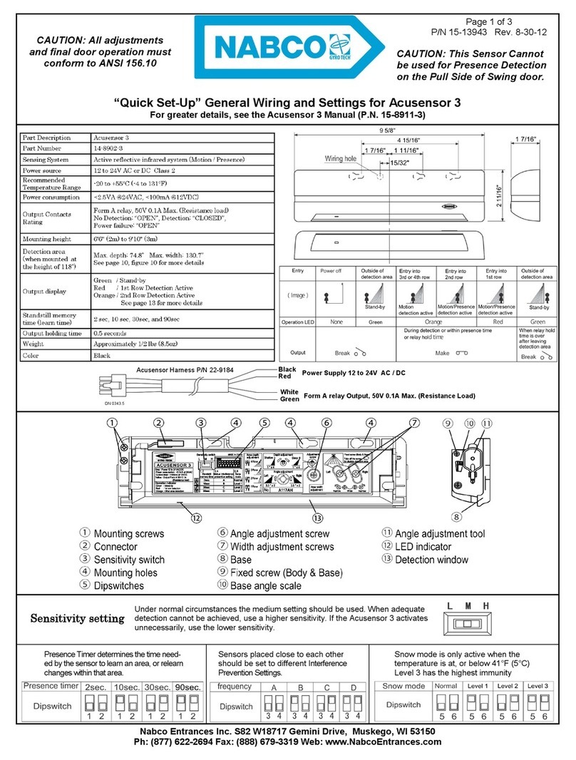
Nabco Acusensor 3 Quick setup

BURG-WACHTER
BURG-WACHTER WS 44 WinSafe Assembly and user's manual

DMP Electronics
DMP Electronics 1125 Installation sheet

EDWARDS SYSTEMS TECHNOLOGY
EDWARDS SYSTEMS TECHNOLOGY IRC-3 Operation manual

Tie Down Engineering
Tie Down Engineering Roof Zone 13809 installation instructions
nordlux
nordlux Egon Mounting instruction
DeWalt
DeWalt DE0892 Original instructions

Shelly
Shelly Shelly Motion manual
