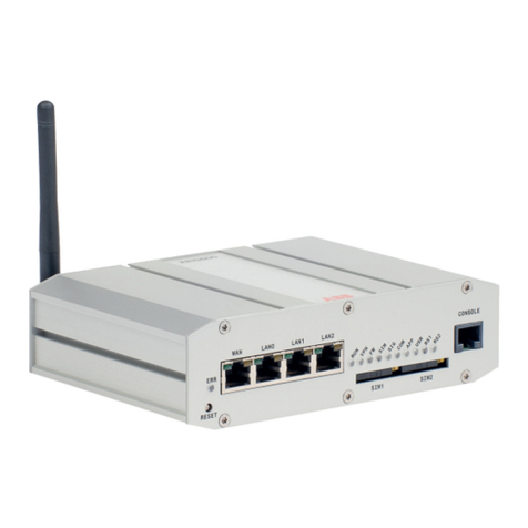
Elcomponent MMTCPBCONV User manual

MMTCPBCONV
Serial/Ethernet
Converter
&
Modbus Gateway
USER GUIDE
01/12/2006 V02
Unit 5 Southmill Trading Centre, Southmill Road, Bishop’s Stortford, Herts. CM23 3DY
01279 503173 sales
@
elcom
p
onent.co.uk www.elcom
p
onent.co.uk

Ethernet Gateway Set-Up
Please refer to the following pages for detailed instructions on the correct
procedures for setting up the Ethernet gateway.
Please note the following settings should be used:
Module IP The IP address being allocated to the gateway
Default Gateway IP The default gateway IP address being allocated.
If this is not available (enter zeroes in these fields)
Subnet Mask The desired subnet mask
Socket Timeout 90
Converter Mode 0
Char Timeout 0
Port Number N/A
Server IP N/A
Baud Rate 4800
Data Bits 8
Stop Bits 1
Parity None
RS232/RS485 RS485
Serial Reply Timeout 25
RS485 On Delay 5
RS485 Off Delay 0

PROCON ELECTRONICS 10 Ethernet/Serial Converter
7.4 Connecting To a PC which is not Connected to a Network.
If the PC is equipped with an Ethernet card but not connected to a network, a local
network address should be used for communication between the Converter Module and
the PC. The Converter Module is shipped with a default IP address 169.254.111.111.
This address is in the address area reserved for local networks not connected to the
Internet. For direct connection between the PC and the Converter Module, a crossover
Ethernet cable is required.
To setup your PC to connect directly to the Converter Module, an IP address in the same
range as the Converter Module must be assigned to the PC. In Windows environments,
this should be done as follows:
• Connect the PC and the Converter Module together using a crossover cable
• Open the Windows Control Panel
• Select Network
• Select TCP/IP -> the PC's Ethernet adaptor from the Configuration tab as shown
below

PROCON ELECTRONICS 11 Ethernet/Serial Converter
• Click the properties button. A TCP/IP Properties box similar to the one below should
appear
• Select the IP Address tab
• Choose to Specify an IP address as shown in the figure
• Insert the IP address 169.254.111.112 and the corresponding subnet mask as shown
• Save your settings by pressing OK in both TCP/IP properties and Network properties
• Reboot your PC
7.5 Connecting to a PC which is Connected to a Network.
If there is an Ethernet network available, the Converter Module can be connected to any
Ethernet connection or hub belonging to the network. If the PC is connected to a network,
there is a strong possibility that the default IP address of the Converter Module is outside the
range of the network (the address doesn't belong to the IP subset of the network). If the
Ethernet network is connected to the Internet, this is certain. In this case a new IP address for
the Converter Module is required. Contact the local network administrator to be assigned a
free IP address for the Converter Module. The new IP address is programmed into the
Converter Module using a Web browser software such as Internet explorer. In this case the
Converter Module must first be connected directly to a PC as described above.
In the remainder of this chapter, the IP address 169.254.111.111 is used as an example.
Exchange this IP address with the IP address you have set up in all the occurrences.
Lan/
Internet

PROCON ELECTRONICS 12 Ethernet/Serial Converter
7.6 Testing the Connection
To test the connection between the PC and the Converter Module, a simple program called
ping can be used. Ping sends a number of messages to the specified IP address and displays
the response. The ping program can be run from the command line or from a DOS window on
the PC, as follows:
• Open the Windows Start Menu
• Click Run
• In the Open box, type: "ping 169.254.111.111"
If the network connection is OK, the program will respond with:
"Reply from 169.254.111.111" and information about the response time.
If there is a problem with the network setup the program will respond:
"Destination host unreachable". There may be two solutions to this problem:
• If the PC is connected in a network, change the IP address to an address accessible
from the local network.
• If the Converter Module is connected directly to the PC(or through a hub), change the
PC's IP address to one in the same address range as the Converter Module.
If there is a problem with the Converter Module the program will respond:
"Request timed out", this means that the Converter Module can not respond to messages.
Check the power connection. Check that the Link LED is illuminated when the cable is
plugged into the RJ45 connector.

PROCON ELECTRONICS 13 Ethernet/Serial Converter
7.7 Viewing Web Pages
The Converter Module has built in web pages. These are used for checking the configuration
and dynamic data, and for altering the configuration. To view these Web pages, a Web
browser such as Internet Explorer or Netscape is needed.
To view the default Web page in Converter Module, start the Web browser and type
"169.254.111.111" into the address line of the browser window. The main page of the
Converter Module will now be displayed in the browser window.
If no Web page is displayed, go back to testing the network connection to the Converter
Module by using the ping command. If the Converter Module replies to the ping messages,
check the setup of the Web browser. If the Converter Module is directly connected to the
same network as the PC, "direct connection to the network" or "bypass proxy server for local
addresses" should be selected in the Web browser configuration menu. If the Converter
Module is connected to the PC through a firewall, a proxy server should be selected in the
configuration menu. Contact the local network administrator for information about the network
configuration.

PROCON ELECTRONICS 14 Ethernet/Serial Converter
7.8 Troubleshooting Guide.
No Checkpoint Solution
No
No network connection is detected. The Ethernet
cable is either not plugged in or wrong type of
cable is used. For connection to a network with a
hub or switch, a normal network cable can be
used. For direct connection to a PC network card,
a twisted cable must be used.
1
Is the LINK LED on and is
the ACTIVITY LED
flashing with short
pulses? Yes A network connection is detected, the Converter
Module is connected to the network.
No
Either the PC or the Converter Module is setup
with wrong IP address.
To change the IP address of the Converter
Module back to the default address, remove the
power, open the Converter Module housing and
remove the jumper labeled DEFAULT IP. Apply
power to the Converter Module for a short while.
Now replace the jumper and close the enclosure.
To change the IP address of a PC, use the
Windows "control panel -> network -> TCP/IP
properties" and setup an IP address close to the
Converter Module address. The Converter Module
is shipped with a default IP address of
169.254.111.111, the PC can be setup with an IP
address of 169.254.111.112
2
Does the Converter
Module respond to PING
requests?
Yes The PC and Converter Module are setup with a
correct IP address and they are able to
communicate with each other.
No
This is normally caused by the setup of the Web
browser.
In the "options" or "preferences" menu, check that
the Web browser is configured for direct network
connection or local area network and NOT using a
proxy server.
3
Can the default Web page
be accessed in a Web
browser?
Yes No problems.

PROCON ELECTRONICS 15 Ethernet/Serial Converter
7.9 Parameter Configuration
The Web page address "169.254.111.111/ip.htm" is entered into the address line of the
browser window to access the configuration page. This page allows you to change the IP
address of the Converter Module, select serial timeout, to setup the baud rate of the
Converter Module on the RS485 network, and to enter a Module Description Name for
identification/maintenance purposes.
• IP Address: The new IP address can be entered into the web page as shown above.
After this has been done, you must click the Submit button to send the values to the
Converter Module. The screen will now be updated and if successful will continue to
display the new IP address. The new IP address will only be effective after the
Converter Module power has been switched off and on again. This feature allows you
to check that the correct IP address has been entered before being activated. If the IP
address has been entered incorrectly and the power has not been switched off, it is
possible to re-enter the correct IP address. If the power has been switched off and
back on again, the Converter Module will not communicate until you enter the new IP
address into the address line of the browser window.
• Default Gateway IP Address: A default gateway is a node (a router) on a computer
network that serves as an access point to another network. In enterprises, however,
the gateway is the computer that routes the traffic from a PC to the outside network
that is serving the Web pages. It is only necessary to configure the default gateway
IP address if the PC that is accessing the Converter is on a different network.
• Subnet Mask: In computer networks, a subnetwork or subnet is a range of logical
addresses within the address space that is assigned to an organization. The subnet
mask is used to inform the Converter that it must send its replies to the gateway if the
IP address of the PC is on a different network. When the subnet mask is set to
“0.0.0.0” then it is effectively disabled and the default gateway is not used. A typical
subnet mask would be “255.255.255.0”.

PROCON ELECTRONICS 16 Ethernet/Serial Converter
• Socket Timeout: If a socket connection is broken, say due to a network fault, it must
timeout to free it up so that it can be used again. This timer is triggered by activity on
the converter, so if there is no communications activity for longer than the timeout
period, the socket will close.
• Converter Mode: These modes have been described in detail in a section 2. Enter 0,
1 or 2 as required.
• Char Timeout: This timeout has been described in detail in a section 2. Enter a value
in 10millisecond increments.
• Port Number: The Port number used to tell the converter that the incoming TCP/UDP
message must get sent to the serial port.
• Server IP: The client converter in mode 2 must connect to the server converter. Enter
the IP address of the server converter in this field.

PROCON ELECTRONICS 17 Ethernet/Serial Converter
• Baud Rate, Data Bits, Parity, Stop Bits: The configuration of the serial port can be
configured by selecting the parameters from the pull-down menu. Click on the Submit
button to load these values into the Converter Module.
• RS232/RS485: This field is used to select RS232 or RS485 on the serial port.
• Serial Reply Timeout: This timeout is the time the module waits for a reply from a
slave device. If a reply is received then this timeout is cancelled and the converter
looks for the next TCP message. If the slave does not send a reply, then this timeout
will expire and allow the converter to look for the next TCP message. This timeout
must be longer than the turn-around time of the slave device or it will timeout before
the slave replies. This timeout only operates in Mode 0.
• RS485 On Delay: This is the time the RS485 transmitter will be enabled before data
is transmitted. This has no effect on RS232 communications.
• RS485 Off Delay: This is the time the RS485 transmitter will be enabled after data is
transmitted. This has no effect on RS232 communications.

PROCON ELECTRONICS 18 Ethernet/Serial Converter
• Module Name: This field allows you to enter a module description name into the
Converter Module. This is an identifier for diagnostic/maintenance purposes and is
chosen to best describe the Converter Module in the system by name or number.

PROCON ELECTRONICS 19 Ethernet/Serial Converter
8. Conformity Certificate
DECLARATION OF CONFORMITY
according to EN 45014
Manufacturer’s Name: Procon Electronics CC
Manufacturer’s Address: 26 Wareing Park
2 Wareing Road
Pinetown 3610
South Africa
declares that the product
Product Name: MOD-MUX
Model Number(s): MMTCPBCONV
complies with EMC Directive 89/336/EEC and Low Voltage Equipment Directive 73/23/EEC and
conforms to the following Product specifications:
Safety: IEC 950
EMC: IEC 61000-4-2-A1 Level 2
IEC 61000-4-3-A1 Level 2
IEC 61000-4-4 Level 3
CISPR 11:1991-A1 / EN 55011:1998 Group 1 Class A
Pinetown, SA November 2006
Location Date D.Ruddock
Table of contents
Popular Gateway manuals by other brands
Moxa Technologies
Moxa Technologies OnCell G3100 Series user manual
DEUTSCHMANN AUTOMATION
DEUTSCHMANN AUTOMATION UNIGATE MB - MPI instruction manual
ZyXEL Communications
ZyXEL Communications ZyWALL USG 100 Series user guide

HP
HP StorageWorks P4000 G2 user guide
Siemens
Siemens SMG 71 installation instructions
Encom
Encom Harmony Series user manual
