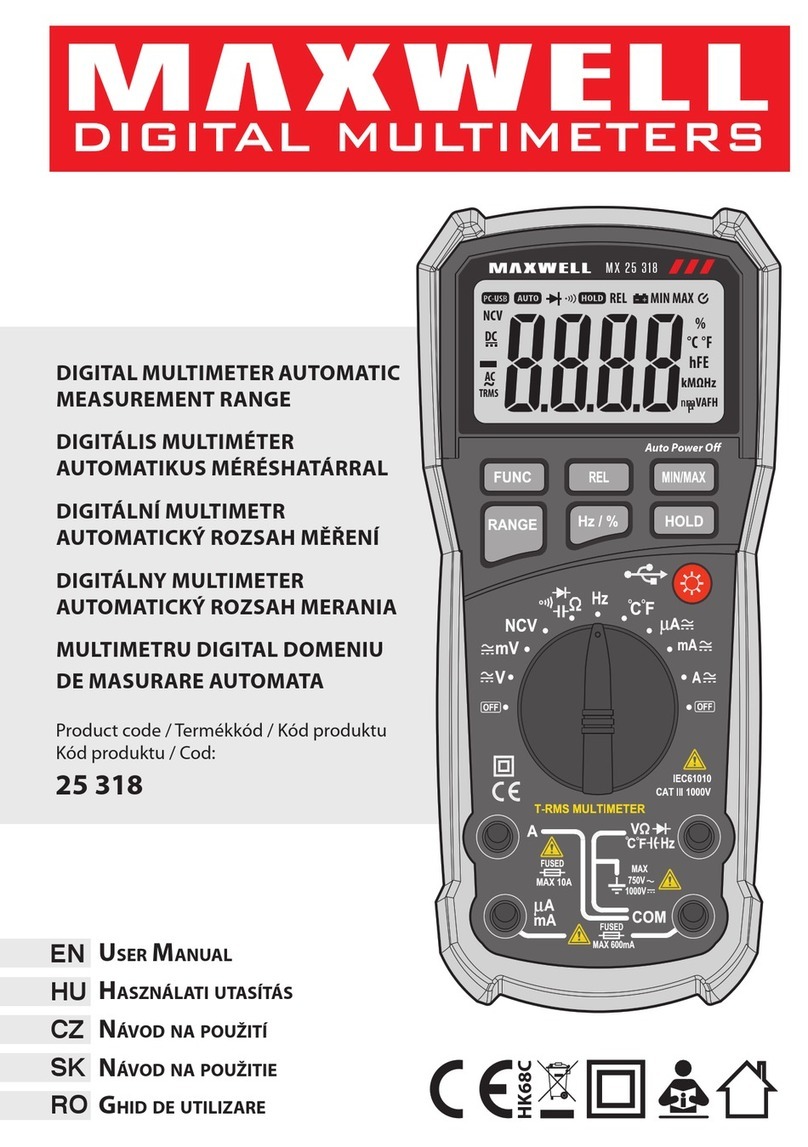
EN User Manual
• ATTENTION: In order to avoid damage to the device
or electric shock, cut o the external power source of
the circuit to be measured, or turn o the high-power
capacitors!
Diode measurement
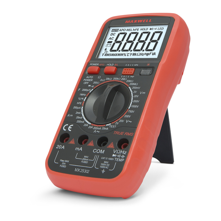
• Set the function selector to position.
• Press the FUNC button to select the function.
• Connect the black test lead to COM, and the red test
lead to
V
jack.
• Touch the red lead to the diode’s anode and the black
lead to its cathode.
• The opening voltage of the diode will be read on the
display. If the polarity is accidentally reversed, the OL
icon will appear on the display.
• ATTENTION: In order to avoid damage to the device
or electric shock, cut o the external power source of
the circuit to be measured, or turn o the high-power
capacitors!
Current measurement
• Set the function selector switch to
A
~
mode
depending on the measurement limit.
• Select the type of current to be measured (direct current
or alternating current) by pressing the FUNC key.
• Turn o the power supply to the circuit to be measured.
• Discharge any high capacity capacitors.
• Connect the black test lead wire to the COM socket
and the red to the mA terminal max. up to 600mA
measurement limit, or for A the max. For 10A
measurement limit.
• Connect the multimeter in series to the circuit.
• Read the measured value from the display. In the case
of DC measurement, the polarity of the red cable is also
shown on the display (only the negative sign).
• If the display shows OL and the device beeps
continuously, switch to a higher measurement limit.
• ATTENTION: If you are not sure of the approximate
value of the measured value, then set the instrument
to the maximum or automatic measurement limit. To
avoid damage to the device, check the condition of
the fuse before measuring! Always use the specied
dimensions and values! When measuring current, do
not connect the instrument leads in parallel to the
circuit, as this can lead to circuit and instrument failure.
Frequency measurement
• Set the function switch to HZ. Connect the test leads to
the COM and
V
sockets. Connect the test leads
to the signal source to be measured.
• Note:
• Do not measure frequency at a voltage higher than
250 V(RMS)..
• In noisy environments, it is advisable to use a shielded
cable when measuring small signals.
• Avoid touching the circuit when measuring at
high voltage.
hFE – Transistor test(25212)
• Set the function selector to the hFE position.
• Connect the measuring adapter to the
V
and
COM sockets.
• Place the transistor to be measured in the test socket
according to its type and pin layout. The current gain
factor of the transistor will be shown on the display.
Duty cycle measurement %
• Set the function switch to Hz, then press the FUNC
button once to measure the duty cycle. Connect the
instrument cable to the COM and
V
sockets and
then to the signal source to be measured.
Capacity measurement
• Set the function switch to the capacity function.
• Press the FUNC button to select the function.
• Place the test lead in the
V
socket and the black
one in the COM socket. Connect the test leads to the
capacitor to be measured.
• Before measuring capacity, discharge the capacitor
to be measured. Measuring mF capacitors can take
several seconds.
• Note: It is normal if the small value of the capacitance does
not return zero, in order to obtain an accurate value, the
readings must be subtracted during the measurement.
MIN/MAX data hold
• Press briey to store and display the minimum or
maximum measurement value.
• Long press exits the function.
REL – relative measurement mode
• For relative measurement mode, press the REL button
briey until a beep sounds to indicate that the function
is on.
• The instrument holds the measured value when you
press the button (this is called the initial value).
• Measure with the instrument. Then the value on the
display will be the sum of the two values.
• Press the button again to return to normal
measurement mode.
• This function does not work in frequency
measurement mode.
NCV (Non-Contact-Voltage) – Non-contact voltage
search
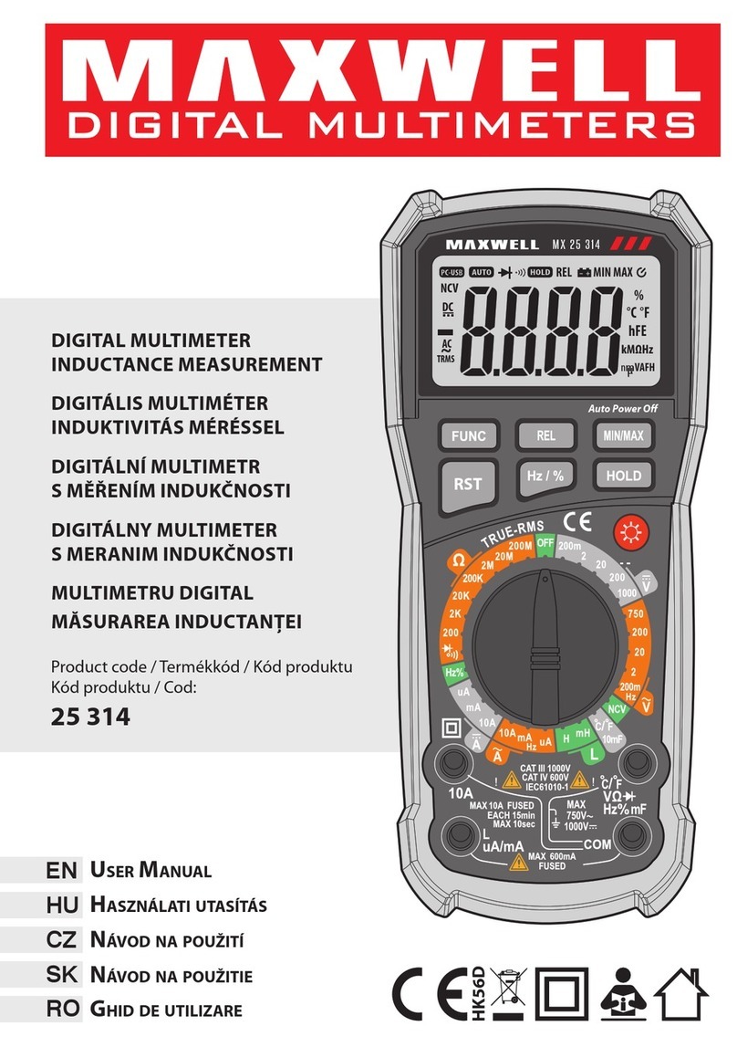
• Set the function selector to the NCV position.
• Bring the top of the instrument (the part above the
display) close to the wire to be tested.
• When voltage is present, the instrument indicates it by
intermittent beeping and ashing of the LED.
LIVE - Phase detection function
• Set the function selector to LIVE position. Press the
FUNC button to select the LIVE function.
• Connect the red test lead to the
V
socket and
touch the measuring tip to the uninsulated end of
the wire to be tested. When a phase is present, the
