Meco 81K User manual

A unique Multi-functional device
Features :
lMulti-Display : Primary 80000
Secondary 80000
Bargraph 23 segments
lBasic DC Accuracy : 0.05%
lmV Impedance : >1000MV
lMore than 50 measuring functions.
lFrequency measurement : 0.5Hz to 1000.000000 MHz
l16 Freguency points, 1% to 99% duty selectable square wave output.
lAnalyzing component of current or voltage signal.
lResistance : 0.1Vto 80MV,10MVto 8000MV
lCapacitance : 1PF to 100mF
lTemperature : -500C to 13720C, -580F to 25020F
ldBm 20 types of reference impedance.
lAuto data hold/peak hold.
lRelative measurement.
l36-hours dynamic recording : MAX / MIN / AVG / MAX-MIN
lCommunication : isolated optical RS232
lTimer for measurement.
lBacklight display.
lAuto power off
34
Brief introduction
These series have two models.
The 80000 is autorange and calibrated by 50Hz sine signal.
The 80000R is also antorange and can offer true RMS measurement.
Safety information
Read this operation manual completely before using the meter to ensure that you use the meter safety
follow the safety guidelines as below :
lUse the meter only as specified in this manual; Other wise,the protection provided by the meter
maybe impaired.
lNever measure voltage while the test leads are inserted into the current input terminals.
lDo not use the meter if it looks damaged .
lInspect the leads for damaged insulation or exposed metal, check test lead continuity. Replace
damaged leads.
lDisconnectthepoweranddischarge allhigh-voltagecapacitors beforetestingin resistance,continuity,
and diode function.
lBe Cautions when working above DC 60V or AC 42V,such voltages may cause a shock hazard.
lWhen making measurement, keep your fingers behind the guards plant on the probes.
lSelect the proper function and range for measurement, To avoid damaging the meter, disconnect
the test leads from test points before change function.
12
®
Digital Multimeter
Function Generator
10 Digit Counter
MODEL : 81K / 81K-TRMS
80000 Series
Function of meter
Terminal
About terminal function refer to table 1
Table 1. terminal
Terminal Function
COM Common terminal for all measurement
Volts, Ohm, Diode, Freq., Temp. and Cap.
V / V/ Hz measurement and square wave output terminal
mA milliampere current measurement terminal
10A Ampere current measurement terminal
Figure 1. terminal
56
78
4.Timer [RS 232]
lPress this button more than 2 seconds the meter enter communication on and "RS232" appear on
display screen .
lAt communication mode auto power off disable.
lPress this button more than 2 seconds again the meter exit this mode and return normal state.
lSetting time for measuring see special functions.
5. H
lPress this button meter enter auto data hold mode and "A-H" appear on display screen .
lThe data hold function allows aperator to hold the dispiayed digital value while analog bar graph
continues showing the present reading.
lAt auto hold mode the meter can refresh hold new stable readings and sound point out.
lPress this button again, the meter enter Peak + hold modc and a "PH+"appear on display screen.
lPress this button again, the meter enter Peak - hold mode and "PH-" appear on display screen.
lPress this button more than 2 seconds the meter exit HOLD mode and return to normal state.
6. 2nd VIEW
1. SELECT
lPress this button you can select your measurement mode.
lWhen meter as square wave output, press this button can select duty of square wave (1% - 99%).
2. RANGE
lWhen power on meter it at auto range mode,press this button can select your measurement range.
lWhile SET button operating the RANGE change asp(moving up) button.Press this button can move
setting digits up.
lPress this push button more than 2 seconds meter return to auto range.
3. MAX / MIN
lPress this button momentary the meter enter dynamic record mode.
lAt dynamic record mode, press this button momentary again to cycle MAX, MIN, AVG, MAX-MIN and
Present Reading on secondary display.
lPress this push button more than 2 seconds meter retum to normal mode .
lAt MAX/MIN state the recording time is 36 hours.
lWhile SET button operating the MAX / MIN change as t(moving left) button. Press this button can
move setting digits left.
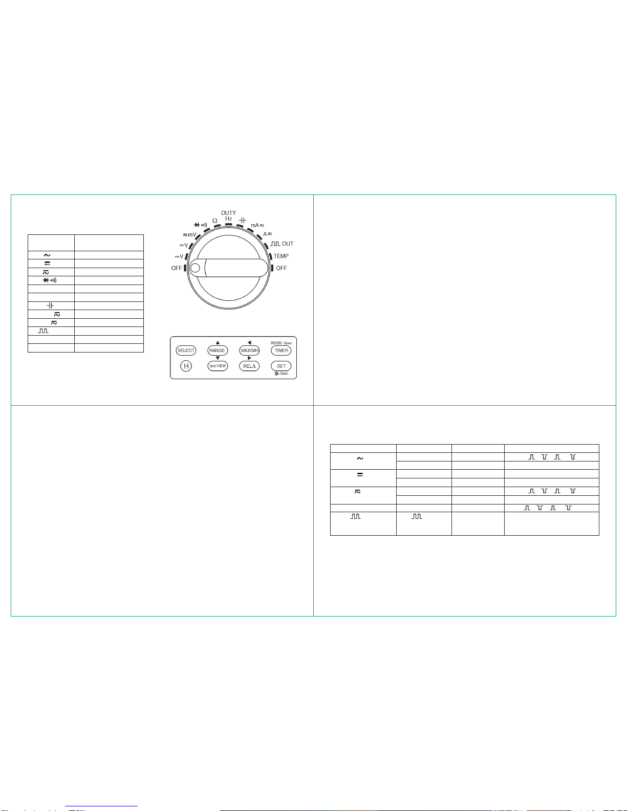
Rotary switch
About rotary switch function refer to table 2
Table 2. functions of rotary switch
position of Function
rotary switch
V AC V
V DC V
mV DC, AC millivoltage
Diode & continuity
VResistance
DUTY/Hz Duty / Frequency
Capacitance
mA -- milliampere current
A ~Ampere current
OUT Squarer wave output
TEMP Temperature
OFF Power off
Push button
Figure 3. Push button
Figure 2. Rotary switch
lUse 2nd VIEW select secondary display functions. table 3 shows press 2nd VIEW button various
measuring states.
Table 3. press 2nd VIEW for secondary display
Rotary Switch position Measure state Primary display Second display
V ACV+Hz ACV Hz/ %/ %/ ms/ ms
AC dBm+Hz AC dBm ACV/Hz
V (ACV+DCV)+Hz ACV+DCV ACV/Hz
dBm+Hz dBm Hz/ACV/DCV/ACV+DCV
mV ACmV+Hz ACmV Hz/ %/ %/ ms/ ms
dBm+Hz dBm Hz/ACmV/DCmV/ACmV+DCmV
Hz / DUTY Hz Hz %/ %/ ms/ ms
OUT OUT Press 2nd VIEW Press SELECT
to change output to change duty value
frequency
lThe meter as square wave output,press this button can selecting frequency :
0.5000Hz/1.0000Hz/2.0000Hz/10.000Hz/50.000Hz/60.240Hz/74.63Hz/100.00Hz/151.50Hzi200.00Hz/
303.00Hz/606.10Hz/1.2500kHz/1.6660kHz/2.5000kHz/5.0000kHz .
lPress this button more than 2 seconds the meter return 606.10 Hz, 50% of duty output state.
lWhile SET button operating the 2nd VIEW change as q(moving down) button. Press this button can
move setting digits down.
7. RELr
lPress this button the meter enter relative measuring state and “RELr”appear on display.In this mode
910
11 12
present readings as Relative reference value and display on secondary.Relative measurement has two
mode.one is RELr= measuring value - Reference value, the other is
REL
%= (RELr/Reference value)
x 100% ( press SELECT to select RELror REL% mode).
lWhile SET button operating RELrbutton change as u(moving right) button.
lSet up reference value for measurement .
1. In every function use RANGE select your range.
2. After press SET once, press SELECT twice the meter enter set up reference value for measurement.
At same time the pqt ubutton are started.
3. Use pqt ubuttons set your reference value.
4. After set up, you can press SET to confirming.
lPress RELrbutton more than 2 seconds the meter return to normal state.
8. SET
lPress this button to starting pRANGE q2nd VIEW tMAX/MIN uRELrbuttons. Use these
buttons set up your digits .At this condition the RANGE, 2nd VIEW, MAX/MIN, RELroriginal functions
are disabled.
lPress this button more than 2 seconds backlight on and press this button again the backlight off.
The light can auto off after it on 30 seconds if does not press this button.
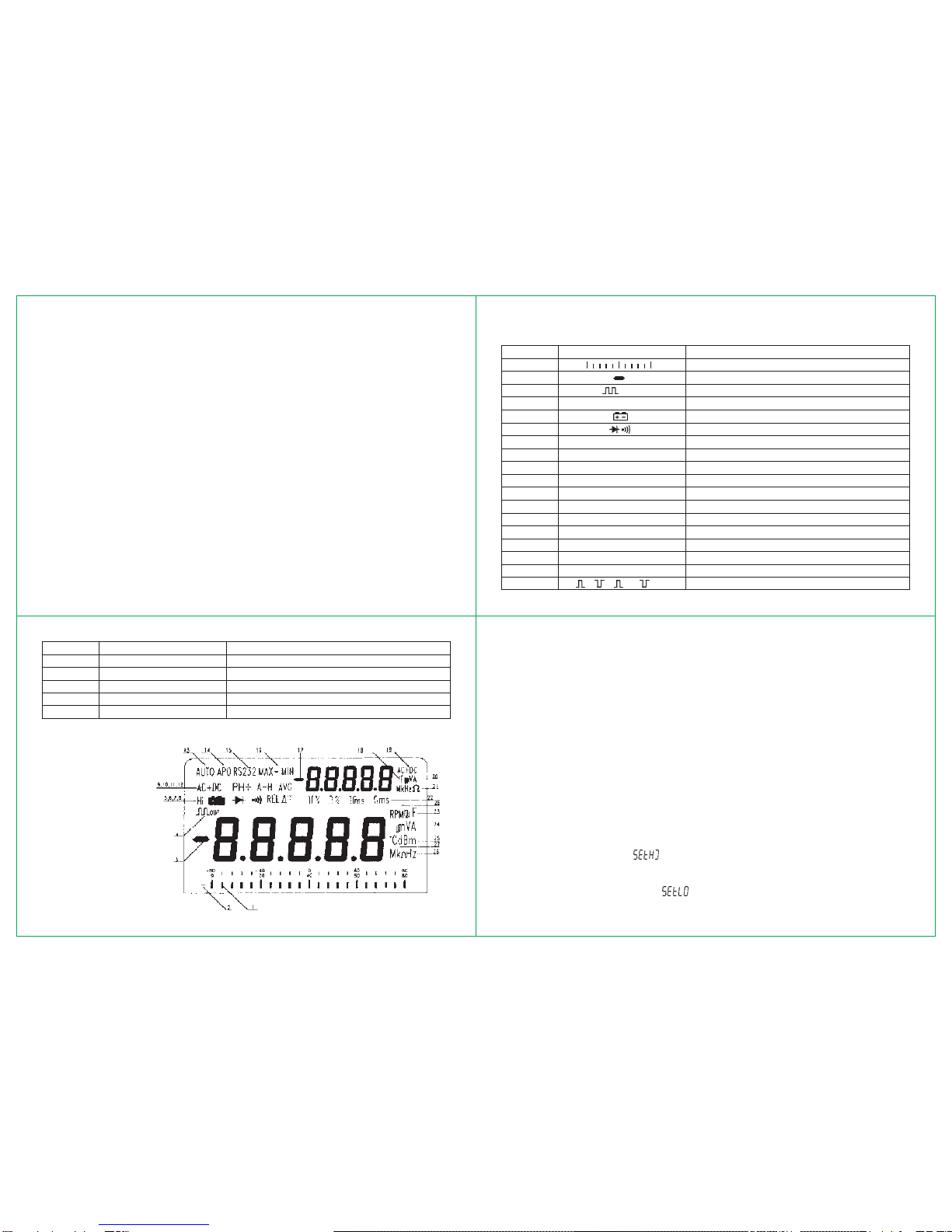
Display
Table 4. symbols of display
Order No. Symbol Description
1 Analog bar graph
2, 3,17 Negative sign
4 OUT Square wave output
5 Hi Hi frequency or themocoupIe indicate
6 Battery power is weakening
7 Diodelaudible continuity function
8 RELr% Relative measurement
9, 19 DC, AC, DC+AC DC,AC, DC+AC voltage or current
10 PH+ PH- + peak hold, - peak Hold
11 A-H Auto Hold
12 AVG Average reading
13 Auto Auto mode
14 APO Auto power off sign
15 RS 232 Communication on annunciation
16 MAX/MIN/MAX-MIN MAX Reading, MlN Reading /MAX-MIN Reading
20 mV/V/mA/A Second display volt and current unit
21 Hz/kHz/MHz/V/kV/MVFrequency and Resistance (ohms) unit [second]
22 % % ms ms Duty cycle unit, pulse width unit
23 nF/ mF Capcitance unit
24 mV/V/mA/A Primary display volt and current unit
25 dBm dBm annunciation
26 Hz/KHz/MHz/V/kV/MVFrequency and Resistance (ohms) unit (primary)
27,18 0C 0F Temperature measurement indicate
28 RPM Round/per minute
Figure 4. Display
Special functions
lAuto power off
The meter has auto power off function, in normal conditions, when the meter is power on, if any push
buttons are not used or rotary switch is not changed, it can auto power off in 30 minutes after power on.
Before power off five minutes, the audible five beepers that points out the meter will power off.In operating
state any push button is used or rotary switch is changed the time of auto power off will recount.
lSet up time for measurement
1. Press TIMER button to set time [ “0.00.00” appear at secondary display].
2. Press SELECT button the last digit of secondary display flash, at the same time, the pqt uare
enable [The first digit of secondary display is hour, the second and third are minutes, tbe forth and fifth
are seconds].
1. Lise pqt ubuttons to select digit of time .
2. Press TIMER button again to confirming Complete this procedure measuring lime is starting .
lSet limited measurement
The meter has set up limited or down limited measurement functions, up limited and down limited setting
as following.
1. Set Up limited : power on the meter gselect range gpress SET gpress SELECT select Up limited
seting state (secondary display “ ”) press moving buttons pqt uto set digits gpress SET to
confirm.
2. Set Down limited : power on the meter gselect range gpress SET gpress SELECT select Down
limited seting state (secondary display “ ”) press moving buttons pqt uto set digits gpress
SET to confirm.
13 14
15 16
lIn the auto range (Auto) mode, the meter selects the best range for the input detected.This allows you
to switch test points without having to reset the range.
lIn the manual range mode you can select the range, this allaws you to override auto range and lock the
meter in a specific range.
lWhen the meter in auto range mode the “AUTO” sign will be appear on display screen.
(3) To enter or exit manual range mode ;
lPress RANGE button momentary the meter enters the manual range mode and “AUTO” turns off.
lEach press of RANGE momentary increments the range. When the highest range is reached, the
meter wraps to the lowest range.
lPress RANGE more than 2 seconds the meter returns to auto range mode and “AUTO” appear on
display screen .
3. After setting proceeding measurement.
a. If measuring above limited the secondary display “ ” and primary display present value .
b.If measuring down limited ihe secondary display “ ” and primary display present value .
c. If mcasuring about high and low, secondary display “ ”
lAnalog bar graph
The Function of bar graph is analog needle of meter but without the overload, and updates 40 times per
second because the graph responds 10 times faster than the digital display it is useful for making peak
andnull adjustments and abserving rapidly changing inputs.Thebar graphhas 23 segments.The number
of lit segments is relative to the full-scale value of the selected range.The unit of the bar graph is 4000
counts/bar except when in the relative mode.The polarity indicated at left of the bar graph.
lSquare wave output
The square wave output is a useful function is Iet user have free space for application. For instance,
PWM (Pulse Width Modulation) out, regulate voltage control, timer to control circuit, synchronous clock,
etc, this is a free-for-all application function.
Measurement ranges
A measurement range determines the highest vatue meter can measure.the meter functions have more
than one range.
(1) Being in the right measurement range is important :
lIf the range is too high, the meter will not display the must accurate measurement; If the range is too
low, the meter will show “OL” on the display.
(2) Auto range and manual range ;
lThe meter bas both auto range and manual range options :
How to operate
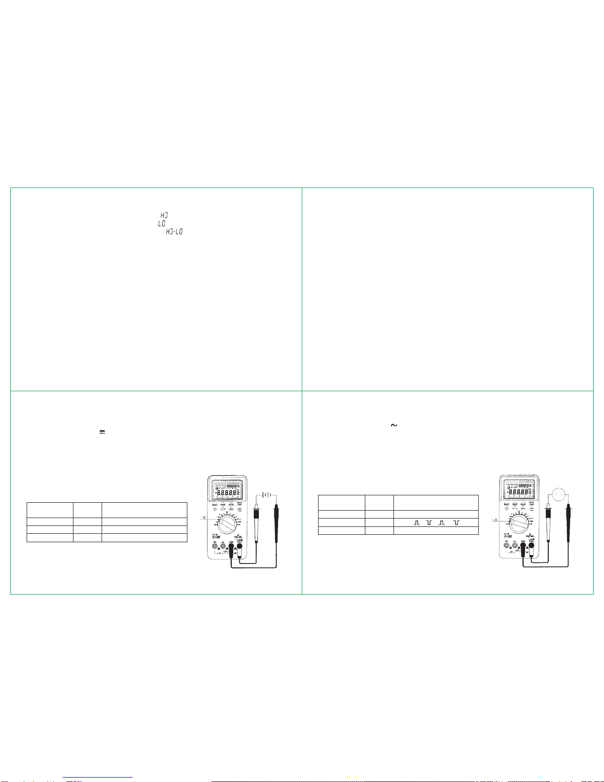
lDC Voltage measurement
The measurement of DCV has three modes : DCV / [DCV+ACV] / dBm.
1. Set the rotary switch to “ V ” position.
2. Press SELECT to select measurement mode.
3. Connect the black test lead to “COM” terminal and the red test lead to “V VHz” terminal.
4. For auto range mode the meter at auto range, if you want some range press RANGE to obtain your
range.
5. According to your need, can press RELrMAX/MIN and 2nd VIEW buttons obtain relevant
measurement .
6. Touch the probes to the test points and reading display.
7. Primary and secondary display as Table 5.
Table 5. primary and secondary display
Press Secondary
SELECT Primary [ press 2nd VIEW ]
DCV DCV
[DCV + ACV ] ACV ACV/Hz
dBm dBm Hz/ACV/DCV/DCV+ACV
Note : When enter to dBm measurement, the impedance is
600 V, if you want change impedance, press RANGE to select
impedance.The impedance selectable is :
4/8/16/32/50/75/93/110/125/135/150/200/250/300/500/600/800/
900/1000/1200 of Ohms. Figure 5. DCV measurement
lAC Voltage measurement
The measurement of AC voltage has three modes : ACV / [ACV+Hz] / dBm.
1. Set the rotary switch to “ V ” position.
2. Press SELECT to select measurement mode.
3. Connect the black test lead to “COM” terminal and the red test lead to “V VHz” terminal.
4. For auto range mode the meter at auto range, if you want some range press RANGE to obtain your
range.
5. According to your need, can press RELrMAX / MIN and 2nd VIEW buttons obtain relevant
measurement.
6. Touch the probes to the test points and reading display.
7. Primary and secondary display as Table 6.
Table 6. primary and secondary display
Press Secondary
SELECT Primary [ press 2nd VIEW ]
ACV ACV
[ACV + Hz ] ACV Hz/ %/ %/ ms/ ms
dBm dBm Hz/ACV
Note : When enter to dBm measurement, the impedance is
600 V, if you want change impedance, press RANGE to select
impedance.The impedance selectable is :
4/8/16/32/50/75/93/110/125/135/150/200/250/300/500/600/800/
900/1000/1200 of Ohms. Figure 6. ACV measurement

17 18
19 20
interference. Some random digits on display but have not effect
on result of measurement.
3. At millivoltage measurement mode in order to obtain DC+AC
function, the input terminal of ADC do not employed coupling
capacitor.There for please never apply more than the double dc
or ac voltage of the rated value of this range.
lAC/DC millivoltage measurement
The measurement of millivoltage has three modes : DCmV / [ACmV+Hz] / dBm.
1. Set the rotary switch to “ mV ” position.
2. Press SELECT to select measurement mode.
3. Connect the black test lead to “COM” terminal and the red test lead to “V VHz” terminal.
4. According to your need, can press RELrMAX / MIN and 2nd VIEW buttons obtain relevant
measurement.
5. Touch the probes to the test points and reading display.
6. Primary and secondary display as Table 7.
Table 7. primary and secondary display
Press Secondary
SELECT Primary [ press 2nd VIEW ]
DCmV DCmV
[ACmV + Hz ] ACmV Hz/ %/ %/ ms/ ms
dBm dBm
Hz/ACmV/DCmV/[DCmV+ACmV]
Note :
1.When enter to dBm measurement, the impedance is 600 V,
if you want change impedance, press RANGE to select impedance.
The impedance selectable is :
4/8/16/32/50/75/93/110/125/135/150/200/250/300/500/600/800/
900/1000/1200 of Ohms.
2. At millivoltage mode the input impedance more than 1000
M V, therefore at test leads opening state input easy caused Figure 7. mV measurement
Warning For Current measurement
To avoid damage to meter or injury, if the fuse blows. Never attempt an in-circuit current measurement.
Where the open-circuit potential to earth is greater than 1000V.To avoid damage to the meter, check the
meter’s fuses before proceeding. Use the proper terminals, function and range for your messurement.
Never place the probes in parallel with a circuit or component when the leads are plugged into the current
terminals.Never test voltage when test lead plug in “mA” or “10A” terminal !
Warning to wrong operation when probes are plugged in to the “mA” or “10A” terminal and the rotary
switch is not at “ mA ” or “ A ” position, meter will beeper warning to wrong operation until rotary
switch at right position or probes pull out “mA” or “10A” terminals.
lAC/DC milliampere current measurement
The measurement of milliampere has four modes :DCmA / ACmA /
[DC mA + ACmA] / [ACmA + Hz].
1. Set the rotary switch to “ mA ” position.
2. Press SELECT to select measurement mode.
3. Connect the black test lead to “COM” terminal and the red test
lead to “mA” terminal.
4. According to your need, can press RELrMAX / MIN buttons
obtainrelevantmeasurement.Turnoff powertothe circuit, discharge
all high-voltage capacitors.
5. Break the circuit path to be tested. Touch the black test lead
to more negative side of the break; Touch the red test lead to the
more positive side of the break. Figure 8. mA Current
measurement
6. Turn on power to the circuit, then read the display.
7. Primary and secondary display as Table 8.
8. Turn off power to the circuit and discharge all high-voltage
capacitors. Remove the meter and restore the circuit to normal
operation. Pull out the red test lead from “mA” terminal.
Table 8. primary and secondary display
Press Secondary
SELECT Primary [ press 2nd VIEW ]
DCmA DCmA
ACmA ACmA
DCmA+ACmA DCmA+ACmA ACmA
ACmA+Hz ACmA Hz
lAC/DC Ampere current measurement
The measurement of ampere current has four modes : DCA /
ACA / [DCA+ACA] / ACA+Hz
1. Set the rotary switch to “ A ” position.
2. Press SELECT to select measurement mode.
3. Connect the black test lead to “COM” terminal and the red
test lead to “10A” terminal.
4. According to your need, can press RELrMAX / MIN
buttons obtain relevant measurement. Figure 9. Ampere current
measurement
21 22
23 24
5. Turn off power to the circuit, discharge all high-voltage capacitors.
6. Break the circuit path to be tested.Touch the black test lead to more negative side of the break.Touch
the red test lead to the more positive side of the break.
7. Turn on power to the circuit, then read the display.
8. Primary and secondary display as Table 9.
Table 9. Primary and secondary display.
Press Secondary
SELECT Primary [ press 2nd VIEW ]
DCA DCA
ACA ACA
DCA+ACA DCA+ACA ACA
ACA+Hz ACA Hz
9. Turn off power to the circuit and discharge all high-voltage capacitors.Remove the meter and restore
thc circuit to normal operation. Pull out the red test lead from “10A” terminal.
lResistance Measurement
Caution
To avoid damage to meter or to the equipment under test,disconneet circuit power and discharge
all high-voltage capacitors before measuring resistance.
The measurement of resistance has three modes : normal, continuity and Hi resistance. Use SELECT
button to select these mode.
lNormal mode
1, Set the rotary switch to “V” position.
2. Connect the black test lead to “COM” terminal and the red test lead to “V VHz” terminal.
3. Touch the probes to the test points and reading display.
Note :The test leads can add 0.1 V~ 0.5 Vof error to resistance measurement, please short test leads
and press RELr
4. According to your need can press RELrMAX / MIN buttons obtain relevant measurement.
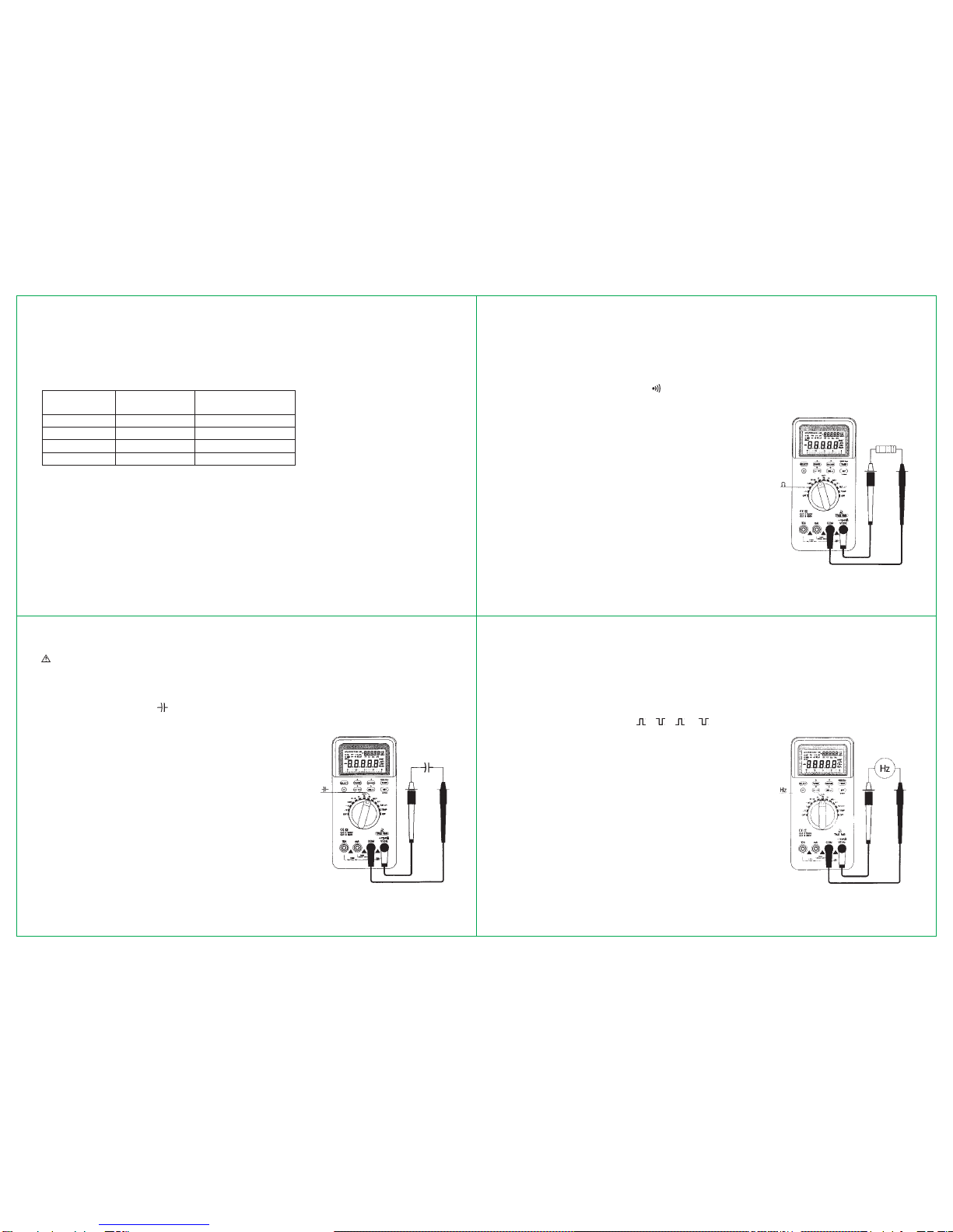
lContinuity mode
At normal mode press SELECT until “ ” sign appear on the display screen.If checking point resistance
fall below 50 Vthe beeper will sound.
lHi resistance mode
At normal mode press SELECT until “Hi” sign appear on display
screen. Using this function can measure above 80M Vresistance.
Figure 10.
resistance measurement
lCapacitance Measurement
Caution
To avoid damage to the meter or to the equipment under test disconnect circuit power and
discharge all high-voltage capacitors before messuring capacitance. Use the DC voltage function
to confirm that the capacitor is discharged.
1. Set the rotary switch to “ ” position.
2. Connect the black test lead to “COM” terminal and the red test lead to “V VHz” terminal.
3. Touch the robes to capacitor’s legs, if the capacitor is a polarity.
The red test lead to the positive leg.
4. Press RANGE option your range, with this method can speedup
measurements of similar values.
5. According to your need can press RELrMAX / MIN buttons
obtain relevant measurement.
Figure 11. capacitance
measurement
lFrequency and rotational speed (RPM) measurement
1. Set the rotary switch to “Hz” position.
2. Press SELECT to select normal, Hi Hz and RPM three Measuring Mode.
3. Connect the probes to signal source and reading display.
4. In normal mode the meter auto ranges to one af six frequencies : 999.99Hz / 9.9999kHz /
99.999kHz / 999.99kHz / 8.0000MHz.
5. Press 2nd VIEW can change %/ %/ ms/ ms.
6. In Hi Hz mode, using Hi frequency accessory to measure
more than10MHz Frequency. The reading is 10-Digit counter
primary display + second display .
7. In RPM mode using rotational speed accessory to measure
rotational speed and reading is RPM.
Figure 12. freq. and rotational
speed measurement

25 26
27 28
lTemperature measurement
1. Set the rotary switch to “TEMP” position.
2. Press SELECT to select Hi or normal test mode.
3. In Hi mode using type K thermocouple to measure temperature.
4. Plug the red leg ( + ) to “V VHz” terminal and the black leg ( - ) to “COM” terminal and reading
display.
5. Press SELECT to “Hi” off the reading is room temperature.
6. Measurement range : -500C -13000C, -580F-25020F.
7. Display : primary 0C, secondary 0F.
Figure 13.
temp. measurement
lDiode and continuity check
Caution
To avoid possible damage to the meter or to the equipment under test, disconnect circuit power
and discharge all high-voltage capacitors before checking diodes.
1. Set the rotary switch to “ ” position .
2. Connect the black test lead to “ COM” terminal and the red test lead to “V VHz” terminal.
3. For diode checking, touch the red test lead to the positive side of the diode and the black test lead
to the negative side.The meter can display diode voltage drop.
A good product a forward bias reading of 0.5V to 0.8V.
4. Reverse the probes and measure the voltage across the
diode again if the diode good “OL” is displayed.
Note :
(1) Near 0V drop is displayed in both directions the diode
shorted .
(2) “OL” is displayed in both directions the diode opened.
5. For continuity checking, while testing continuity, the
beeper will sound if the resistance falls below 50 V.
Figure 12. freq. and rotational
speed measurement
lSquare Wave Output
This meter can output square wave that frequency is selectable by 2nd VIEW 0.5000Hz / 1.0000Hz /
2.0000Hz / 10.000Hz / 50.000Hz / 60.240Hz / 74.63Hz / 100.00Hz / 151.50Hz / 200.00Hz / 303.00Hz /
606.10Hz / 1.2500kHz / 1.6660kHz / 2.5000kHz / 5.0000kHz.
1. Set the rotary switch to “ OUT ” position.
2. Connect the black test lead to “COM” terminal and the red test lead to “V VHz” terminal.
3. Press SELECT to select the duty of 1% to 99%.The square wave output from “COM” and “V VHz”
terminal or test leads.
4. Primary and secondary display as Table 10.
Table 10. primary and secondary display
Function Primary Secondary
[press 2nd VIEW] [press SELECT]
OUT Hz %
5. Press 2nd VIEW more than 2 seconds the meter return to
606.10Hz / 50% duty output state .
Figure 15.
square wave output
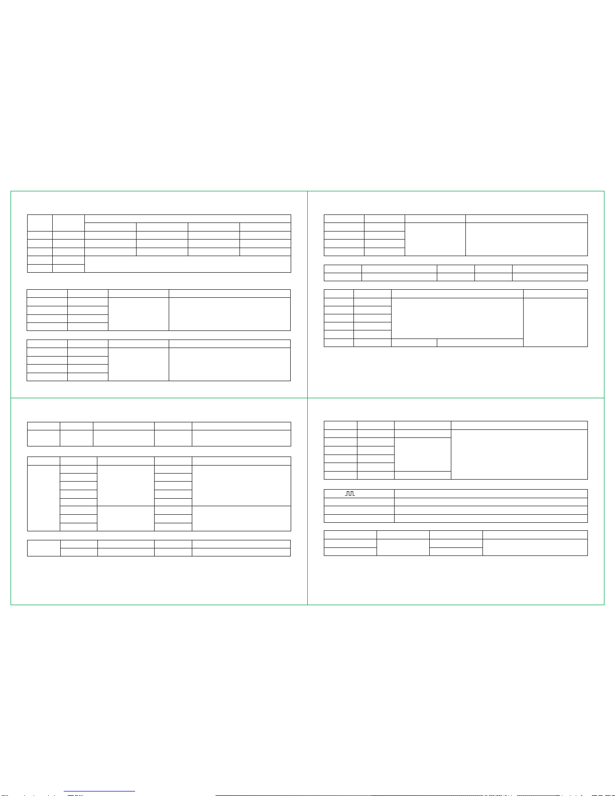
Electrical Specifications
Accuracy is specified for one year after calibration at operating temperatures of 180C to 280C, with
relative humidity at 0% to 75%
Accuracy specifications take the form of : ±(a% of reading + number of least significant digits).
Table 11. DCV
Range Resolution Accuracy Note
80mV 1mV
800mV 10mV
8mV 0.1mV ± (0.05% rdg + 10) Input impedance : 80mV - 800mV>1000MV
80V 1mV 8V - 1000V : 10MV
800V 10mV
1000V 0.1V ± (0.08% rdg + 10)
Table 12. ACV ( True RMS )
Range Resolution Accuracy
50Hz / 60Hz 50Hz - 1kHz 1kHz - 10kHz 10kHz - 20kHz
80mV 1mV ±(0.8% rdg + 10) ±(1.0% rdg + 10) ±(3.0% rdg + 10) ±(8.0% rdg + 10)
800mV 10mV ±(0.8% rdg + 10) ±(1.0% rdg + 10) ±(3.0% rdg + 10) ±(5.0% rdg + 10)
8V 0.1mv ±(0.8% rdg + 10) ±(1.0% rdg + 10) ±(3.0% rdg + 10) ±(5.0% rdg + 10)
80V 1mV
750V 10mV 50Hz - 400Hz : ±(1.0% rdg + 5)
Input impedance : 8mV - 800mV>1000MV, 8V - 1000V, 10MV, Parallel capacitance<100pF
29 30
31 32
Table 13. ACV AVG (60Hz Sine Wave Calibrating)
Range Resolution Accuracy
50Hz / 60Hz 50Hz - 1kHz 1kHz - 10kHz 10kHz - 20kHz
80mV 1mV ±(1.0%0 rdg + 8) ±(1.5% rdg + 8) ±(4.0% rdg + 8) ±(8.0% rdg + 8)
800mV 10mV ±(0.8%0 rdg + 8) ±(1.5% rdg + 8) ±(4.0% rdg + 8) ±(8.0% rdg + 8)
8V 0.1mv ±(0.8%0 rdg + 8) ±(1.0% rdg + 8) ±(3.0% rdg + 8) ±(5.0% rdg + 8)
80V 1mV
750V 10mV 50Hz - 400Hz : ±(1.0% rdg + 5)
Input impedance : 8mV - 800mV>1000MV, 8V - 1000V, 10MV, Parallel capacitance<100pF
Table 14. DCA
Range Resolution Accuracy Note
80mA 1mA
800mA 10mA± (0.5% rdg + 10) Fuses : F 800mA / 250V F 10A / 250V
8A 0.1mA Voltage drop : i800mV
10A 1mA
Table 15. ACA ( True RMS)
Range Resolution Accuracy Note
80mA 1mA
400mA 10mA 50Hz - 2kHz Fuses : F 800mA / 250V F 10A / 250V
8A 0.1mA ± (0.8% rdg + 10) Voltage drop : i800mV
10A 1mA
Table 16. ACA AVG (60Hz Sine Wave Calibrating )
Range Resolution Accuracy Note
80mV 1mA
400mV 10mA 50Hz - 500Hz Fuses : F 800mA / 250V F 10A / 250V
8A 0.1mA ± (0.8% rdg + 10) Voltage drop : i800mV
10A 1mA
Table 17. dBm
Function Range Accuracy Resolution Note
dBm -80.00dBm--- + 80.00dBm ±1.0% rdg 0.01dBm
Table 18. Resistance(V)
Range Resolution Accuracy Note
800V0.01V
8KV0.1VOverload protection
80KV1V±(0.3% rdg+10) 250V RMS
800kV10V
8MV100V
80MV1kV±(2.5% rdg+8) 60MV-80MV : ±(3.5% rdg+10)
Table 23. Square wave output
OUT Description
Voltage amplitude 3V approx.
Frequency 0.5Hz ~ 5000Hz
Duty cycle 1% ~ 99%
Table 24. Temperature
Temp Accuracy Resolution Note
-500C ~ 13720C±(2.5.% rdg+8) 10Ctype K themocouple
-580F ~ 25020F1
0
F
Table 22. Capacitance
Range Resolution Accuracy Note
500PF-1nF 1pF ±(5.0% rdg+10)
10nF 10pF
100nF 100pF
1mF 1nF ±(3.0% rdg+10) Overload protection : 250V RMS
10mF 10nF
100mF 100nF ±(3.5% rdg+10)
Table 20. Frequenc (Hz)
Function Range Accuracy Resolution Note
999.99Hz 0.01Hz
9.9999kHz 0.1Hz Overload protection : 250RMS
99.999kHz ±(0.05% rdg+5) 1Hz Sensitivity : 0.7 RMS
Frequency 999.99kHz 10Hz
8.0000MHz 100Hz
10.0MHz 1kHz
100.0MHz ±(0.1% rdg+5) 10kHz Plus adapter
1000.0MHz 100KHz
Table 21. Rotational speed (RPM)
Rotational Range Accuracy Resolution Note
speed 99999 ±(0.1% rdg+5) 1RPM Plus adapter
Table 19. Diode
Function Range Accuracy Resolution Note
Diode 8.0000V ±(0.3% rdg+5) 0.0001V Diode positive Voltage drop
Overload protection: 250V RMS
33 34
35 36
General Specification
Maximum voltage between any terminal and earth ground : 1000V RMS
Cantinuity Beeper: 3kHz Approx.
Display:Double Digital : 80000
Bar graph : 23 segments, update 40 time/sec
Temperature : Operating : 00Cto + 500C Storage : -200Cto + 600C
Altitude : Operating : under 2000m Storage: under 10,000m
Relative Humidity : i75% at 00C to + 400C i45%at + 400C to + 500C
Battery Type : 9V zinc, NEDA 1604 or 6F22 or 006p.
Battery Life : Alkaline : ~500hrs, carbon-zinc: 200hrs typical.
Size : 37 x 90 x 190mm
Weight : 650g
Electromagnetic Compatibility : in a RF field of IV/m on all. ranges and function except Capacitance :
total Accuracy = specified + 5% of range Capacitance not specified in RF fields performance above
1V/m is not specified. Safety / Compliance : IEC 61010 CAT II 1000V CATIII 600V.
Maintenance
This meter is precise device, Do not attempt to repair or service your meter you are qualified to do so
andhavethe relevantcalibration performance test, andserviceinformation.These products are intelligent
meter, use self-calibrating technology. To avoid the specification error. All components not replaced
except that if is specified.
General Maintenance
Periodically wipe case with a damp cloth mild detergent.Do not use abrasives or solvents.Dirt or moisture
in the terminals can affects readings.To clean the terminals.
1. Turn the meter OFF and remove all test leads.
2. Clean out any dirt that may be in the terminal.
3. Soak a new swap with a cleaning and oiling agent.
4. Work the swab around in each terminal the oiling agent insulates the terminals from moisture
Related contamination.
Battery Replacement
Waring
To avoid electrical or are blast, or personal Injury or damage to the meter, use specified fuses
ONLY in accordance with the following procedure
The meter is powered by a 9V battery (NEDA 1604, 6F22, 006P), Replace battery if the low battery sign
“ ” displayed. Use the following procedures to replace the battery.
1. Set the rotary switch to “OFF” position.
2. Pull up test leads from terminals.
3. Loosen the screw on battery case, pull up and moce the case.
4. Replace the defective battery.
5. Reverse the procedure of opening to close the battery case.
Fuse Replacement
Waring
To avoid electrical shock or personal injury, remove the test leads and any input signals before
replacingthe Fuses.To preventdamages or injury,install ONLY replacement fuseswith the ampere,
voltage, and speed ratings specified.
1. Perform steps 1.2.35. of battery replacement procedure
2. Install new fuse of some size and rating.
Accessories
Manual .........................1 Test leads .................... 1
Battery (9V)..................1 Protective holster......... 1
Options
80KP-1 Rotational speed adapter
80KP-2 Hi frequency adapter
RS-232 Package
TP-03 Type K termocouple
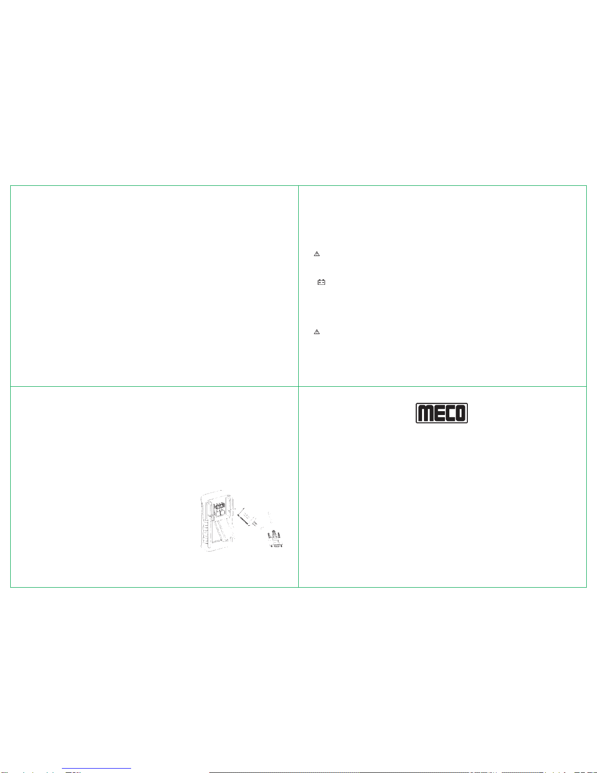
RS232 adapter installation
Thismeter hasa communicationcapability. Thisfunctionwill assist
user to recording and keeping data easy. We have affer RS232
ADAPTER to optional accessories.The RS232 ADAPTER include
a cable with photoelectric receiver and a software disc. We will
continuous release ncw version per year. So you can contact the
place of purchase to update the software.
Please refer following procedures if you want to communicate with
personal computer.
1. Power on the meter and then press the TIMER push button
more than 2 seconds, the symbol “RS232” will appear on
the display.
2. Fixes one side of cable to the hoIster of meter and connect
the 9 pin’s terminal of cable to communication port 1 or 2 of
personal computer. See the follow figure
3. Execute the software to take the date for your necessary. Figure 16. RS232
adapter installation
SR. NO. : .................................
CHECKED BY : .................................
®
DATE : .................................
MODEL NO. : .................................
MECO METERS PVT. LTD.
Block 9, Plot 270, 2nd Floor, Rup-Udey Niwas, Sion (E), Mumbai - 400 022 (INDIA)
Correspondance Address :
Plot No. EL-1, MIDC Electronic Zone, TTC Industrial Area,
Mahape, Navi Mumbai - 400710 (INDIA)
Tel : 0091-22-27673311-16, 27673300 (Board) Fax : 0091-22-27673310, 27673330
Certificate of Calibration
We hereby certify that this product has been calibrated and found to be in accordance
with the applicable SPECIFICATIONS and STANDARDS.
Accuracies of the standard equipment used in this calibration are traceable to the National
Standards.
This manual suits for next models
1
Table of contents
Other Meco Multimeter manuals


