Eldes EWP-EXT User manual

INSTRUCTION MANUAL
Rev.1219MM

Features:
Installation on the wall
Coverage 15 m, angolo 90°
Frequency microwave
10.525 GHz
Alarm technology
DSP(Digital Signal Processing)
Detecting distance
From 5 to 15 m
Detection areas
8 zones for every detector
Installation height
0,8-1,4 m (suggested 1m) 2,1 m (with braket)
Detecting mode
Selectable: AND or triple AND
Power supply
3-10 Vdc
Protection polarity inversion
Yes
Low battery display
Yes, via led, minumum 2,7 V (tipical)
Stand by consumption
< 12 uA
Max consumption
35 mA
Alarm contact
NC-NO 50mA
Microwave setting
Trimmer
Alarm time
2 s
Displaing Led
Blue: alarm
Red: IR up and down
Yellow: Microwave
Detection Speed
Between 0.2 and 3 m/s
RFI/EMI Immunity
10 V/m tra 0.1MHz-2 GHz
Light Immunity
>10000 Lux
Tamper
NC-NO 100 mA
Programming
By dip Switch
Working temperature
Da -20°C a +60° C
IP Protection
IP54
Autocompesation IR
Yes, both
Warm up time
60 s
Inhibition time
3 minutes
Item description:
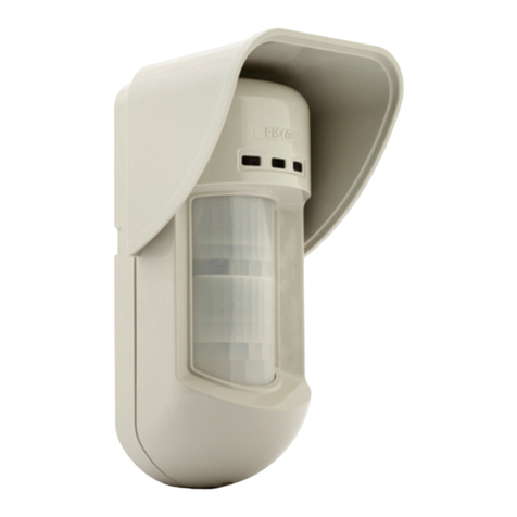
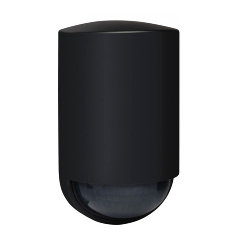
Triple technology outdoor detector made with double infrared sensor and microwave.
Adjustment of microwave flow by trimmer placed inside.
Case for wireless
transmitter
Tamper
Displaing Led
Microwave range setting
Dip switch
Blocking screw
for IR range
Plugs
Cover
Screw
IR distance range
IR range setting

Height adjustment of the lower PIR sensor to perfectly adjust the flow and reduce false
alarms, with three angles of inclination A - B - C.
Immune to animals weighing less than 20 kg and height less than 80 cm if placed in AND
and installed at 1 m height
Coverage diagram:
Plant view
Side view at 1 mt mounting
2,1 m
15 m
8,2°
15105
Side view at 2,1 mt mounting with bracket
Triple AND configuration. Position 5-10-15m
Double AND configuration
Using the bracket you can change the height of fixing
Using the bracket you can change the height of fixing

2AND configuration pos. 5
2AND configuration pos. 10
2AND configuration pos. 15
Using the bracket you can change
the height of fixing
Using the bracket you can change
the height of fixing
Using the bracket you can change
the height of fixing
Detections :
AND configuration (3AND) pos. 15m
Using the bracket you can change the height of fixing
AND configuration (3AND) pos. 10m
Using the bracket you can change the height of fixing
AND configuration (3AND) pos. 5m
Using the bracket you can change the height of fixing

Installation
For a correct functioning of the triple technology detector it is necessary to know that:
• The microwave is sensitive to any movement, never point the detector towards hedges or
tree fronds. Adjust the flow rate appropriately.
• Metal surfaces reflect the microwave by changing its flow rate.
• The two passive infrared sensors are sensitive to sudden thermal variations. Avoid
pointing the detector directed towards the sun. In the presence of animals, adjust the
detection angle appropriately and always use the triple AND (3AND) condition.
• The detector at the first power supply has a stabilization time of about 1 minute.
Plugs:
Plugs AS/C-NC-NO : Tamper. Connect C-NC for normally close, connect C-NO for
normally open.
Plugs AL/C-NC-NO : Alarm. Connect C-NC for normally close, connect C-NO for
normally open.
Plugs + - :Power supply. Connect the battery (3/10V)
Fix the case for wireless transmitter to the wall or to the bracket, connect the wires of
the alarm input and of the tamper to the wireless transmitter and make them pass
through the appropriate hole. Close the case with the appropriate screws. Remove the
IR and microwave sensor block (4 screws) from the detector’s case and drill a hole for
passing cables. Fix the detector on the case for wireless transmitter. Reassemble the
sensor block. Connect the battery connectors. Perform the coverage tests.
Settings
ON
1 2 3 4
By default the setting DIP are setting as shown.
DIP1
Low battery display (SGN BAT)
ON
If the battery has a voltage lower than 2.7 V, the yellow LED flashes
rapidly every 2 s (approx.). During the walk test this signal is
interrupted
OFF
No displaing

DIP2
Triple AND (3AND)
ON
Detection in triple and is enabled. To generate an alarm, the two
pyroelectric devices and the microwave must detect an intrusion at the
same time. Recommended in the presence of animals.
OFF
Detection in triple and disabled. To generate an alarm it is sufficient
that one of the two pyroelectrics and the microwave detect an intrusion
at the same time. Use only in stable and animal-free environments.
DIP3
Alarm Led (LD AL STBY)
ON
The device displays intrusion on the LEDs even during low consumption
operation. Only the central blue LED lights up to signal the intrusion
OFF
The device does not display intrusion on the LEDs during low-power
operation. No LED lights up.
DIP4
Working Test/coverage (WALK TEST)
OFF→ON
An OFF ON transition on this dip allows you to perform the time and /
or coverage test. Once the period of time has elapsed, the device
returns to the set-up of consumption even in ON. To reactivate the test,
set the dip switch to OFF and, after a few seconds, set it to ON. The
entry and exit from the trial period is signaled by the simultaneous
flashing of the three LEDs..
Signaling LED
The following table summarizes the meaning of the LEDs during the walk test and the low
consumption operation.
LED
Walk test
Low consumption
Red
One of the two pyroelectric detects
intrusion
No signaling
Yellow
Flashing during movements, steady
on if microwave alarm is reached
Short flash every 2 s (approx.) If active
low battery warning (DIP1) and if battery
below threshold
Blue
Intrusion alarm on steady
Intrusion alarm if DIP3 activated otherwise
no signaling
Working test and setting
Portare il Dip 4 da OFF a ON, controllare e regolare l’area di copertura. Muoversi all’interno
dell’area da proteggere verificando l’accensione dei LED. Poiché il led rosso è condiviso da
entrambi i piroelettrici, si suggerisce, per regolare la portata IR, di regolare al massimo il
trimmer della microonda (RANGE MW), disattivare la funzione 3AND (DIP2), azzerare il
trimmer del piroelettrico basso (IR-L) e regolare il trimmer del piroelettrico alto (IR-H)
osservando il led rosso. Una volta terminato, attivare la funzione 3AND (DIP2) e regolare
altezza e trimmer IR-L osservando il led blu di allarme. Infine regolare il trimmer della
portata microonda (RANGE MW).

Inhibition time
Between two alarm detections there is an inhibition time of about three minutes in which
the sensor does not open the alarm contact. If during this time the sensor detects a further
movement, the inhibition time is reset and starts again from zero.
Installation suggest :
Install the detector perpendicular to the
ground so that the upper detection area is
parallel to the ground
If the detector is installed at a certain angle
(not perpendicular), the reliability of
operation can be reduced
The fixing height must be between 0.8 and
1.4 meters.
Attraversamento –Fonti luminose –Oggetti mobili
Install the detector in such a way that the
coverage area must be crossed.
It is recommended to prevent the detector
from being hit by direct sunlight or other
strong light sources
Check that there are no moving objects
(leaves, branches, etc.) in the protected
area.

N.B. In the presence of hedges or bushes that can generate false alarms, use the
supplied beam cover lens, covering the beams of the infrared to avoid it as shown
in picture.
Table of contents
Other Eldes Security Sensor manuals
Popular Security Sensor manuals by other brands
Velleman
Velleman K7101 quick start guide
Navim Group Company
Navim Group Company EsiWelma Sensigas ESN.F.O Series manual
Vallen
Vallen spotWave 201 instruction manual
Stahl
Stahl Intrinspak operating instructions
Emirel
Emirel A3 03N quick start guide

General Monitors
General Monitors TS4000 instruction manual


