ELEC-MECH SAFE-AID TS7000 User manual

TS7000
TELESCOPICCRANESOPERATORS’MANUAL
VERSIONVIII
October21

TS7000 TELECSOPIC CRANE OPERATORS MANUAL - VERSION VIII
Page 2
The purpose of this manual is to provide the customer with the operating
procedures essential for the promotion of proper machine operation for its
intended use. The importance of proper usage cannot be overstressed. All
information in this manual should be read and understood before any attempt is
made to operate the machine.
Since the manufacturer has no direct control over machine application and
operation, conformance with good safety practice in this area is the
responsibility of the user and his operating personnel.
All procedures are based on the use of the system under proper operating
conditions, with no deviations from the original design. Alteration and or
modification of the equipment is strictly forbidden without prior written approval
from Elec-Mech (Pty) Ltd.
The Safe-Aid TS7000 (rated capacity indicator (RCI) / Load Moment Indicator
(LMI)) is only to be regarded as an aid to the operator. When the parameters
are set correctly, the indicator will warn the crane operator of an approaching
overload condition or a condition that could cause damage to equipment,
property, and/or injury to the operator or the site workers in the vicinity of the
crane and its load.
This system under no circumstances must be used as a substitute for the good
judgement of a crane operator when carrying out approved crane-operating
procedures, therefore the responsibility for the safe operation of the crane lies
with the crane operator. The system will not necessarily prevent damage due to
overloading and related causes, if not set properly.
Before operating a crane equipped with a Safe-Aid TS7000 RCI the operator
must read the information in this manual carefully. Correct functioning of the
system depends upon routine daily inspection and any suspected faults or
apparent damage should be immediately reported to the responsible person
before using the crane.

TS7000 TELECSOPIC CRANE OPERATORS MANUAL - VERSION VIII Page 3
Contents
SYSTEMUSE–FIGURE1......................................................................................................................................4
SYSTEMSTARTUP–FIGURE2&3........................................................................................................................5
TILTORLEVELSET‐UP–FIGURE4........................................................................................................................6
CRANECONFIGURATIONSELECTION..................................................................................................................7
COUNTERWEIGHT–FIGURE5..........................................................................................................................7
OUTRIGGERBASE–FIGURE6...........................................................................................................................8
BOOMCONFIGURATION–FIGURE7...............................................................................................................9
FIFTHOUTRIGGER–FIGURE8.......................................................................................................................10
WINCH–FIGURE9.........................................................................................................................................11
REEVING–FIGURE10....................................................................................................................................12
DEDUCTIONS–FIGURE11.............................................................................................................................13
PROGRAMCONFIRMATION–FIGURE12......................................................................................................14
OPERATINGSCREENS–FIGURE13,14,15&16...............................................................................................15
ERRORMESSAGES‐FIGURE17ANDTABLE#1.................................................................................................19
SAFE‐AIDTS7000SYSTEMERRORTABLE–TABLE#1........................................................................................20
WORKINGOPERATIONS–FIGURE18&19.......................................................................................................24
INDICATINGSTATUSLIGHTS‐DUMPOUTPUT(LEVERCUT‐OFF)–TABLE#2..................................................27
TOUCHSCREENCALIBRATION–FIGURES20,21&22......................................................................................30
WINDSPEEDSETUP–FIGURES23,24&25–OPTIONAL.................................................................................32
PROGRAM&REEVINGLOCKOUT–FIGURES26,27,28&29...........................................................................33
SCREENBRIGHTNESS–FIGURES30&31..........................................................................................................35
SETDATE&TIME–FIGURES32&33................................................................................................................36
QUICKUSEFLOWCHART...................................................................................................................................37
INSTALLATIONDETAILS.....................................................................................................................................38
TS7000 TELECSOPIC CRANE OPERATORS MANUAL - VERSION VIII Page 4
SYSTEMUSE–FIGURE1
The TS7000 unit is designed with ease of operation in mind. The crane configuration is
selected and confirmed by the operator before the system goes into its operating/monitoring
screen requiring no further input from the operator unless the crane configuration is changed.
Before this is done the crane will remain in safe mode, i.e., the dump circuit (cut-off) will be
operational (if the crane has a dump system fitted). All inputs to the system are done by the
operator via the touch screen including the buzzer override function and momentary bypass.
The touch screen is sensitive to touch therefore it is not necessary to push hard on the
screen (if touch screen does not work or selects incorrectly see Touch Screen Calibration).
Figure 1
TS7000 TELECSOPIC CRANE OPERATORS MANUAL - VERSION VIII
Page 5
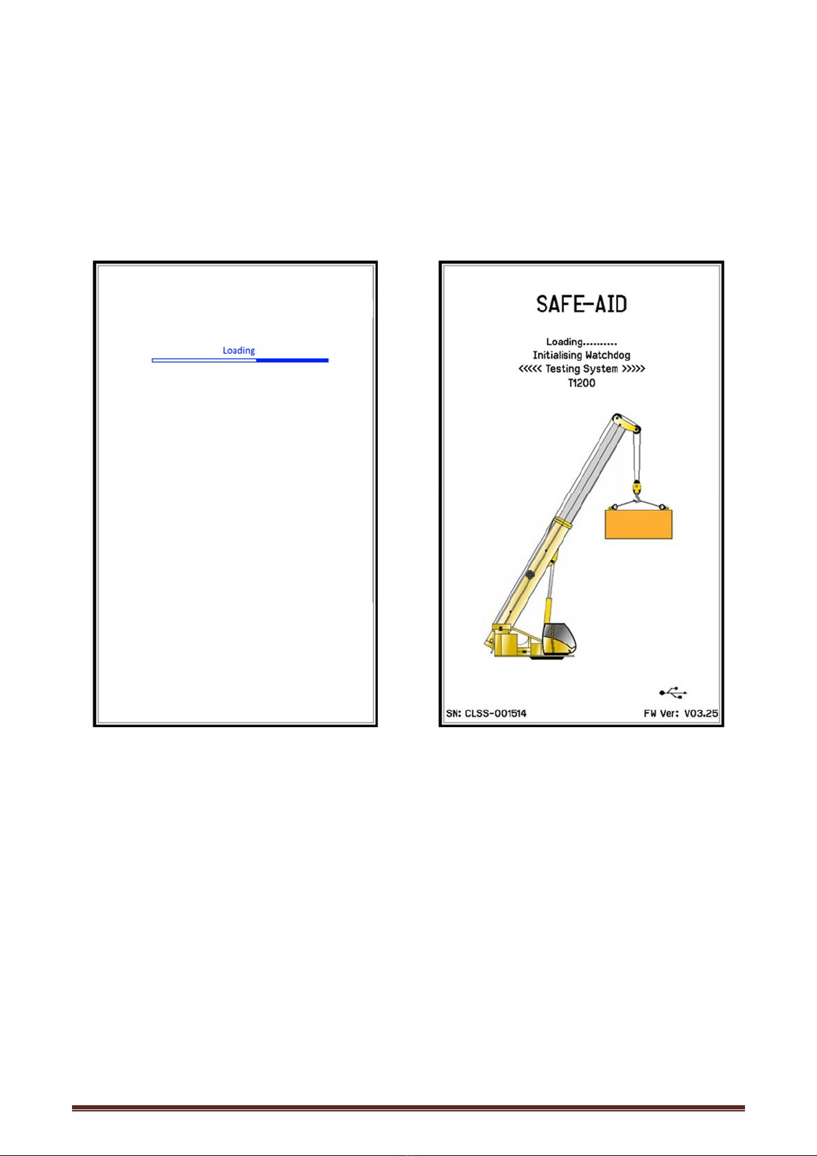
SYSTEMSTARTUP–FIGURE2&3
The TS7000 display (LMI) will automatically come on when the crane is powered up, the
buzzer will sound once then the system will run a CRC (cyclic redundancy check) to make
sure that all raw data is correct.
Once the system has completed the CRC the buzzer will sound again, and a set of internal
diagnostics (watchdogs) will be utilised to verify that all inputs and outputs are working
correctly.
Figure 2 Figure 3

TS7000 TELECSOPIC CRANE OPERATORS MANUAL - VERSION VIII Page 6
TILTORLEVELSET‐UP–FIGURE4
This step will be skipped in the following conditions:
No tilt board is fitted
Tilt board is fitted but no tilt values have been entered
The following option is to determine whether the crane is level along the X & Y axis. Level
the machine using the dark black lines running along the axis lines. The machine will be level
once the lines are as close to the centre forming a cross. Press the Exit button to continue.
Figure 4

TS7000 TELECSOPIC CRANE OPERATORS MANUAL - VERSION VIII Page 7
CRANECONFIGURATIONSELECTION
The system will now run through a series of selections to establish the current crane configuration.
These selections are setup by the crane manufacturer and correspond to the relevant load chart and
may not be displayed or in the same order as laid out in the manual.
Use the back button to start the complete selection from the beginning at any time.
Once the selection has been done the system will memorize the last selection and when powered up
again will show the program confirmation screen. See Program Confirmation.
Some manufacturers have telescoping monitoring conditions that may require the boom to be fully
retracted before changing the configuration, in this case a Retract Boom message will be displayed
when trying to change the configuration with the boom extended.
Laid out below are the most common selections available
COUNTERWEIGHT–FIGURE5
Select the counterweight that is currently in use.
Figure 5

TS7000 TELECSOPIC CRANE OPERATORS MANUAL - VERSION VIII
Page 8
OUTRIGGERBASE–FIGURE6
Select the configuration of the carrier that is currently in use.
Figure 6

TS7000 TELECSOPIC CRANE OPERATORS MANUAL - VERSION VIII Page 9
BOOMCONFIGURATION–FIGURE7
Each boom configuration can be selected by pushing on the configuration that is required.
Some manufacturers have telescoping monitoring conditions that may require the boom to
be fully retracted before changing configuration, in this case a Retract Boom message will
be displayed when trying to change the program with the boom extended.
The correct selection of the configuration is imperative as this determines the correct
rated capacities and work areas. If selected incorrectly, a higher rated capacity than
allowed could be selected for that crane configuration, this is very dangerous as it can
cause the boom to bend / break or the crane to tip / fall over.
Figure 7
TS7000 TELECSOPIC CRANE OPERATORS MANUAL - VERSION VIII
Page 10
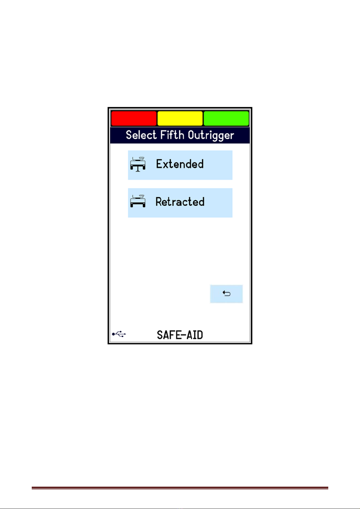
FIFTHOUTRIGGER–FIGURE8
Truck mount cranes may be fitted with additional outriggers (front jack / rear jack or both)
which can be extended (down) or retracted (up). This influences the rated capacities when
working over the front or rear of the crane either by decreasing the capacities or giving a slew
error when the 5th outrigger is retracted (Figure 3). Simply key the option required - if the
5th outrigger is down then select extended if it is up select retracted.
Figure 8

TS7000 TELECSOPIC CRANE OPERATORS MANUAL - VERSION VIII Page 11
WINCH–FIGURE9
This step will be skipped in the following conditions:
The system has been programmed with only one winch.
The reeving has been fixed in rigging mode.
The following option is to determine the winch being used for lifting. Simply select the option
required. Select the relevant winch.
Winch 1 – Main Winch
Winch 2 – Auxiliary Winch
Figure 9
While working in the main running screen and the winch needs to be changed or if
an error has been made, press the picture of Winch 1 (main winch) or Winch 2
(auxiliary winch). Select the required winch followed by the correct reeving.
TS7000 TELECSOPIC CRANE OPERATORS MANUAL - VERSION VIII Page 12
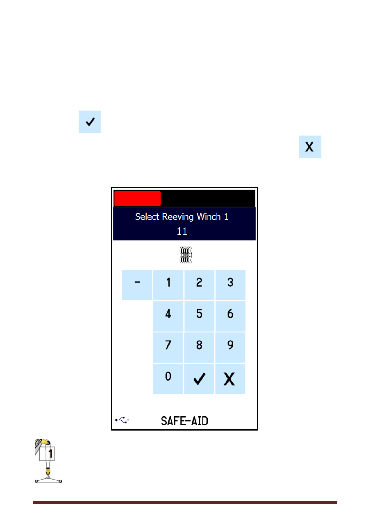
REEVING–FIGURE10
This step will be skipped in the following conditions:
The system has been programmed with fixed reeving.
The reeving has been fixed in rigging mode.
A fixed hook has been selected (cannot be reeved).
After winch selection, how many reeves (falls) the hook is reeved to (total parts of line
between hook block and sheave wheels) must be selected. A numerical keypad will be
displayed, key in the number of reeves on the winch (i.e. Winch #1 or Winch #2), followed by
the enter key (e.g. if Winch #1 (main winch) was selected Select Reeving Winch 1will
be displayed). If the incorrect number is keyed in simply press the clear button and
start again. Once the enter button is pressed the next selectable option or the operating
screen will appear.
Figure 10
While working in the main running screen or if an error has been made and the
reeving needs to be changed, press the block on the main running screen where
the winch rope goes down to the lifted load and the system will respond by
changing to the Reeving entry screen.

TS7000 TELECSOPIC CRANE OPERATORS MANUAL - VERSION VIII Page 13
DEDUCTIONS–FIGURE11
This step will be skipped in the following conditions:
No deductions for the relevant program are available.
On cranes where the main boom can be used with the fly jib erected or the main hook block
is on while the fly jib is being used, the crane manufacturer may give deductions that must
be taken off the rated load when using that configuration. The total of all the selected
deductions will be automatically deducted from the rated capacity, this is done by the TS7000
once the correct options have been selected when prompted (figure 9). Press the deduction
required and a will be displayed on the right of the selected deduction, if more than one
deduction is required select all the deductions (figure 10). Once all the deductions have been
selected press to continue.
Figure 11

TS7000 TELECSOPIC CRANE OPERATORS MANUAL - VERSION VIII Page 14
PROGRAMCONFIRMATION–FIGURE12
This screen will only be displayed if the system has been programmed to allow this, if
this is not programmed the system will go through all the selections again on power
up.
If none of the configuration settings have changed when powering up to the confirmation
screen confirm by pressing the to continue to the working screen. If any of
the configurations have changed then press the and the system will
automatically go to the first configuration selection. Select the correct configuration step by
step and the system will automatically save the configuration for the next start up.
Figure 12

TS7000 TELECSOPIC CRANE OPERATORS MANUAL - VERSION VIII Page 15
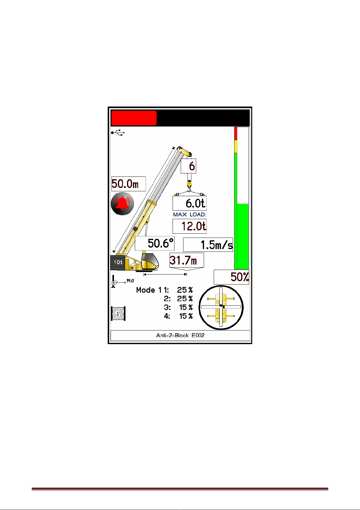
OPERATINGSCREENS–FIGURE13,14,15&16
All the crane and system information can be viewed from here including all the parameters
selected from power up. Should a different program need to be selected, press the crane
graphic on the screen, the system will go back to the beginning as on system start up. Repeat
the steps above.
Figure 13 Figure 14
Figure 15 Figure 16
TS7000 TELECSOPIC CRANE OPERATORS MANUAL - VERSION VIII Page 16
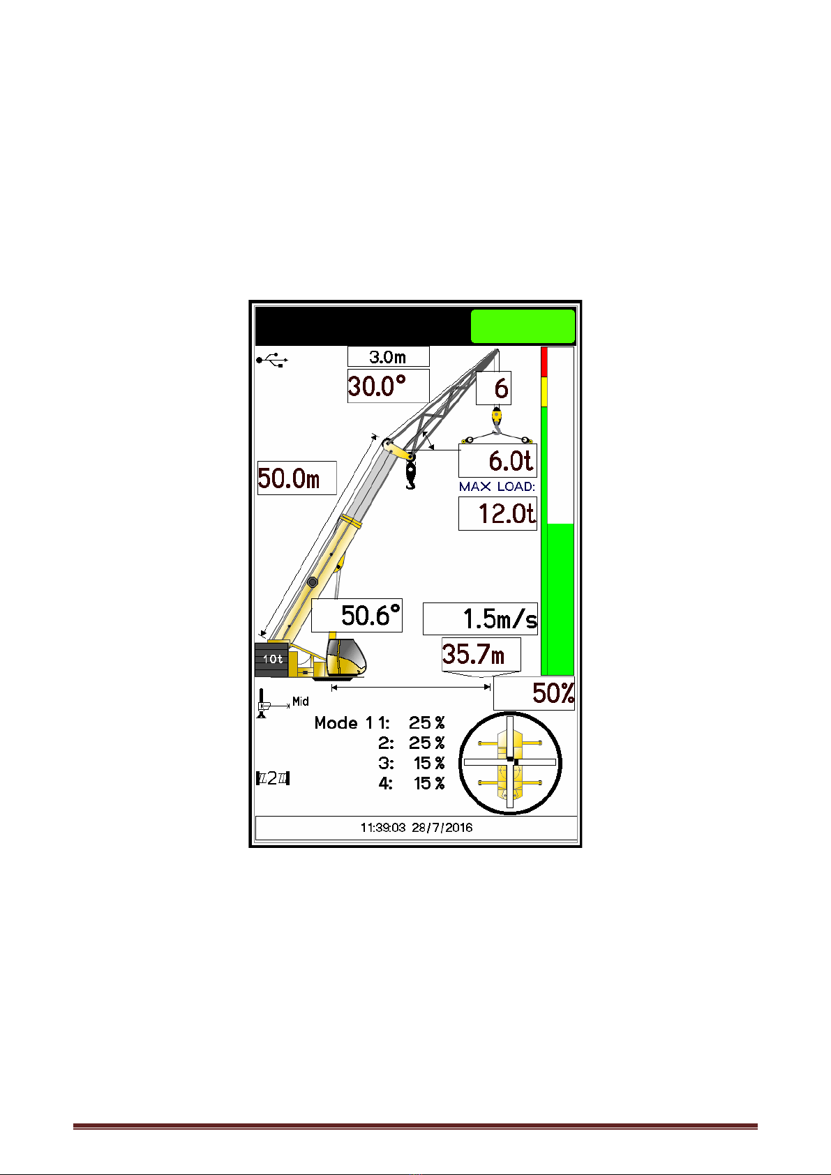
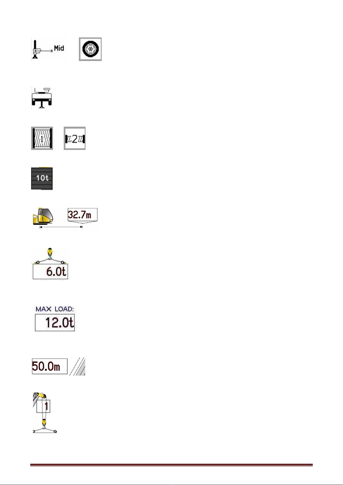
In operating mode, you can see all the current parameters of the crane.
or Outrigger Base: This is the current outrigger base – can be
represented by the outrigger picture with outrigger length or a picture of a tyre with the crane
travel speed.
Fifth Outrigger: This is the fifth outrigger position
or Winch: This is the winch selected
Counterweight: This is the total weight of counterweights fitted
Radius: This is the current radius from centre line of rotation to the
centre of the hook block (load) if the hook block (load) is suspended and hanging vertical.
Lifted Load: This is the load on the hook at the present time, if the green light
and the load are flashing it is a tare load (the tare has been pressed).
Rated Capacity: This is the load allowed to be picked up with the selected
configuration at that current radius as specified by the manufacturer.
Main Boom Length: This displays the current total main boom length.
Reeving: This is the current reeving (number of falls) selected.

TS7000 TELECSOPIC CRANE OPERATORS MANUAL - VERSION VIII Page 17
Main Angle: This displays the main boom angle.
Fly Length: This displays the selected or measured
fly length.
Fly Angle:A fixed angle will be shown for a fixed fly and for a
monitored fixed fly the angle will change as the fly angle changes. The fixed fly angle is
measured relative to the main boom i.e. 0° being straight with the main boom and
increasing as the offset to the main boom increases.
Luffing Fly Angle:If a luffing fly is fitted, the luffing fly angle will be shown in
the fly angle box. The luffing fly angle is measured relative to ground level i.e. 0° is the fly jib
parallel to the level ground.
Utilisation: Percentage utilisation is the percentage of rated load used by the
current lifted load.
Utilisation Bar: The percentage utilisation is also displayed graphically by a bar graph,
going from green (0% - 89%), then amber (90% - 99%) and finally red (100% and above)
increasing incrementally with the percentage utilisation.
Date & Time: This is the current date and time.
Wind Speed: This is the current windspeed (live value) in the units of
measure selected.
Boom Telescope Percentages – This shows the current mode and the
boom section percentages.

TS7000 TELECSOPIC CRANE OPERATORS MANUAL - VERSION VIII Page 18
Area Selection: This is not user selectable and shows the current area the crane is
working in:
360 Degrees Over Side & Rear Direct Over front
Direct Over Rear Direct Over Front & Rear Over Side
Over Front and Side Over Front Outrigger Over Rear Outrigger
To Outrigger To Outrigger
Level/Tilt: The cross through the area selection represents the X & Y axis
while the two lines in the axis are the positioning of the crane (see Tilt or Level setup).
Area Selection Potentiometer: The black segment in the perimeter circle
represents the position of the boom relative to the carrier.
TS7000 TELECSOPIC CRANE OPERATORS MANUAL - VERSION VIII Page 19
ERRORMESSAGES‐FIGURE17ANDTABLE#1
The TS7000 will sound a buzzer and the green block will be replaced by an orange or red
block at the top of the screen if any error occurs on the system. These errors are displayed
at the bottom of the screen as either an error code only or the error description with the error
code e.g., Anti-2-Block E002 where program selection is normally displayed. If more than
one error occurs the errors will scroll on the bottom until rectified.
Figure 17
For all the errors, we have given indication of the problem and the common
solutions, these can be done by the operator or an individual who has some
basic crane knowledge. If the given solution does not work, please contact the
original installer or someone from our service network.

TS7000 TELECSOPIC CRANE OPERATORS MANUAL - VERSION VIII Page 20
SAFE‐AIDTS7000SYSTEMERRORTABLE–TABLE#1
CODE SCREEN DISPLAY INDICATION OPERATOR SOLUTION
E001 Slew Error Boom is not over an area covered by the current
configuration selected. Slew the boom into a safe working area.
E002 Anti-2-Block The main or auxiliary hook has been pulled up too close
to the boom head sheave wheels. Lower Winch 1 or 2.
E003 Anti-2-Block Fly The hook has been pulled up to close to the fly jib tip
sheave wheel. Lower Winch
E004 90% Overload The lifted load is greater than or equal to 90% of the
rated capacity
Move load into safe working position -
winch down, boom up or retract boom.
E005 Overload The lifted load is greater than or equal to 100% of the
rated capacity
Move load into safe working position -
winch down, boom up or retract boom.
E007 Length Exceeded
The length allowed for the selected configuration has
been exceeded or the length is greater than maximum
manufacturer's specified len
g
th.
Retract boom & check configuration
selection is correct.
E008 Low Angle The angle of the boom is below the crane manufacturer's
minimum specification. Raise boom.
E009 Extend Boom You are working below the specified working length for
the selected boom configuration.
Extend boom to the correct working length
& check program selection.
E010 Rope Overload The maximum line pull specified by the manufacturer has
been exceeded.
Put Load down – check correct reeving
selected.
E025 Telesequence Error The boom has been telescoped incorrectly NOT
according to the manufacturer's specifications.
Retract boom fully and telescope according
to the manufacturer's specifications.
E027 Main A400 No Coms No communication between main angle board and
motherboard/display. Call installer or service technician.
E028 Aux A400 No Coms No communication between auxiliary angle board and
motherboard/display. Call installer or service technician.
E029 M400 No Coms
No communication between mother board and display.
Call installer or service technician.
Table of contents


