BMC LD6 User manual

LD6 & MD8 BACKHOES
OPERATOR’S MANUAL for
Back Hoes
Fron End Loaders
Fron Blades
Power S eering
Trenchers

Table of Contents
Page
Safety Precautions 1
General Information 2
LD6 Backhoe
MD8Backhoe 4
LD6 and MD8 Backhoe Box Parts 5
LD6 Backhoe Installation 6-12
MD8 Backhoe Installation 1 -19
LD6 and MD8 Bucket Installation 20
LD6 and MD8 Hose Installation 21-25
Controls 26-27
Operations 28- 4
Backhoe Removal and Storage 5
Backhoe Installation After Storage 5- 6
General Maintenance 6- 8
Torque Charts 9
Hand Signals and Decals 40
Specifications (LD6 and MD8) 41-42
Pre-Delivery Checklist 4

SAFETY PRECAUTIONS
ATTENTION! BECOME ALERT! YOUR SAFETY IS INVOLVED!
1
The following precautions are suggested to help
prevent accidents. A careful operator is the best
operator.
BACKHOE SAFETY PRECAUTIONS
1. Read the Operator’s Manual carefully to acquaint
yourself with the backhoe. Working with unfamiliar
equipment can lead to accidents.
2. Use the handholds and steps when getting on and
off the backhoe.
. Replace safety and warning decals when they become
illegible.
4. For safe operation observe proper maintenance
and repair of all pivot points, hydraulic cylinders, hoses
and main attaching bolts prior to each day’s operation.
5. Always be sure of water, gas, sewage and electrical
line location when operating the backhoe.
6. Watch for overhead and underground high voltage
electrical line before you start to dig.
7. Operate the backhoe controls only when properly
seated at the controls.
8. Do not use the backhoe for a hoist.
9. Never allow anyone to get under the backhoe when
the boom or dipper arm is raised or stabilizers are
raised.
10. Always be watchful of bystanders when lowering
the stabilizers or operating the backhoe.
11. To prevent upsets, avoid full reach and swinging a
loaded backhoe bucket to the down hill side when
operating on a slope.
12. Always lower the bucket to the ground, shut off
the engine and apply parking brakes before getting off
the unit.
1 . Never attach pulling devices to the ROPS or
backhoe for pulling purposes, as the unit can tip
rearward.
14. Keep the operator’s platform free of debris.
15. Adequately block up the backhoe when it is
detached from the tractor.
Whenever you see this symbol it means:
TRACTOR SAFETY PRECAUTIONS
1. Do not start the engine while standing beside the
tractor. Always sit in the tractor seat when starting the
engine.
2. Do not get off the tractor while it is in motion.
. Use an approved roll bar and seat belt for safe
operation. If your tractor is not equipped with a roll
bar and seat belt, see your tractor equipment dealer.
4. Always use the seat belt when the roll bar is
installed. Do not use the seat belt if the roll bar is
removed from the tractor.
5. Do not permit anyone but the operator to ride on
the unit. There is no safe place for extra riders.
6. Lower the bucket to the ground, shut off the engine
and apply the parking brake before getting off the
tractor.
7. Do not operate the tractor engine in an enclosed
building without adequate ventilation. Exhaust fumes
can suffocate you.
8. Never leave the unit when it is parked on an
incline. Always park the unit on level ground where
possible. If the unit is parked on an incline, always
lower the bucket so that the cutting lip contacts the
ground, apply the parking brake and securely block the
wheels.
9. Use care when operating on grades to maintain
proper stability. Also drive at speeds compatible with
safety, especially when operating over rough ground,
crossing over ditches, slopes, or when turning.
10. Use SMV warning signs on the tractor when
traveling on public roads both day and night.
11. Use the flasher / turn signal lights when traveling
on public roads both day and night unless prohibited by
law.
12. Never pull from the tractor rear axle or any point
above the axle. Doing so may cause the tractor to upset.
1 . Always check overhead clearance, especially
when transporting the unit.
14. Do not lubricate or make mechanical adjustments
while the unit is in motion or when the engine is
running.
15. Never make repairs or tighten the hydraulic hoses or
fittings when the system is under pressure, when the
engine is running, or when the backhoe cylinders are
under a load.
16. Always wear safety glasses when servicing or
repairing the machine.
GENERAL INFORMATION
2
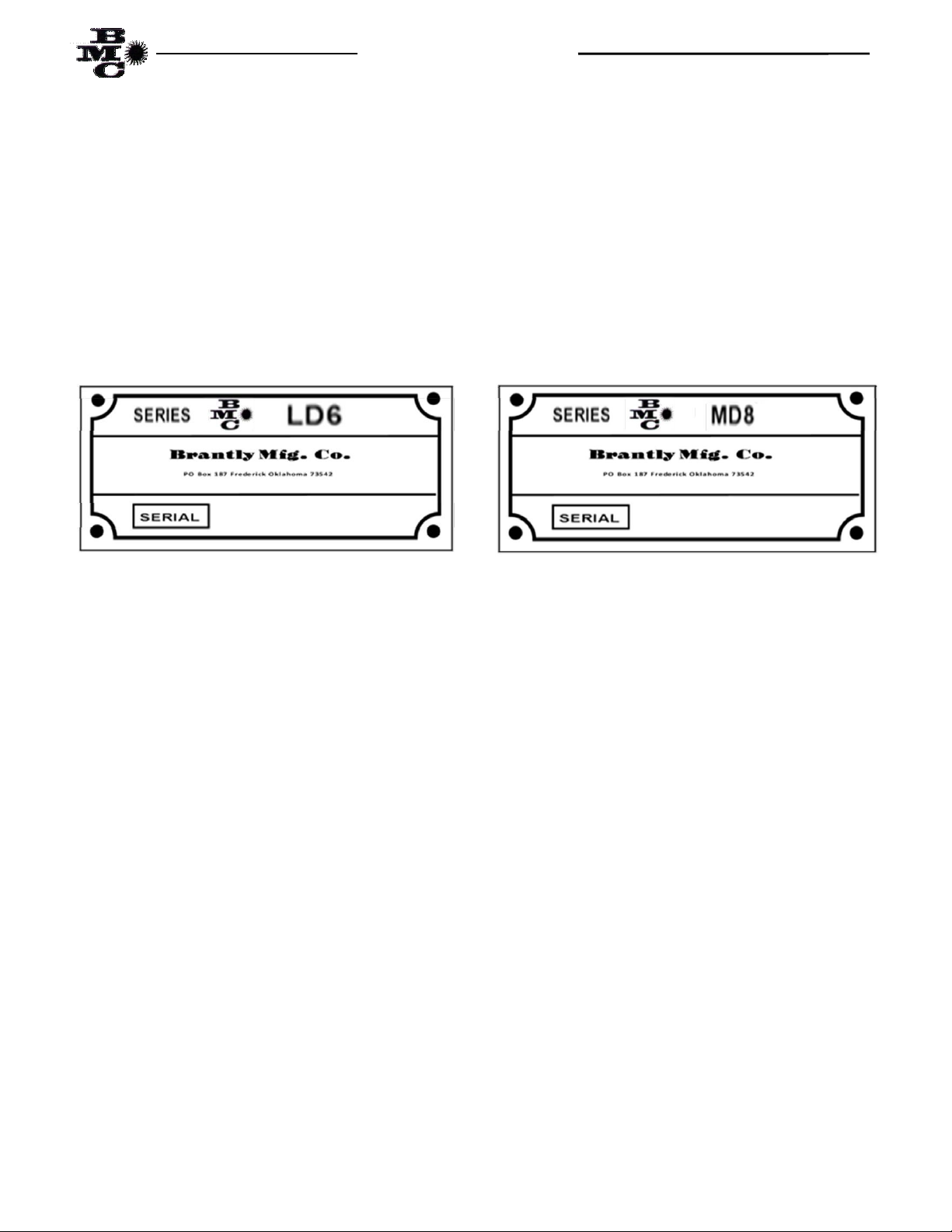
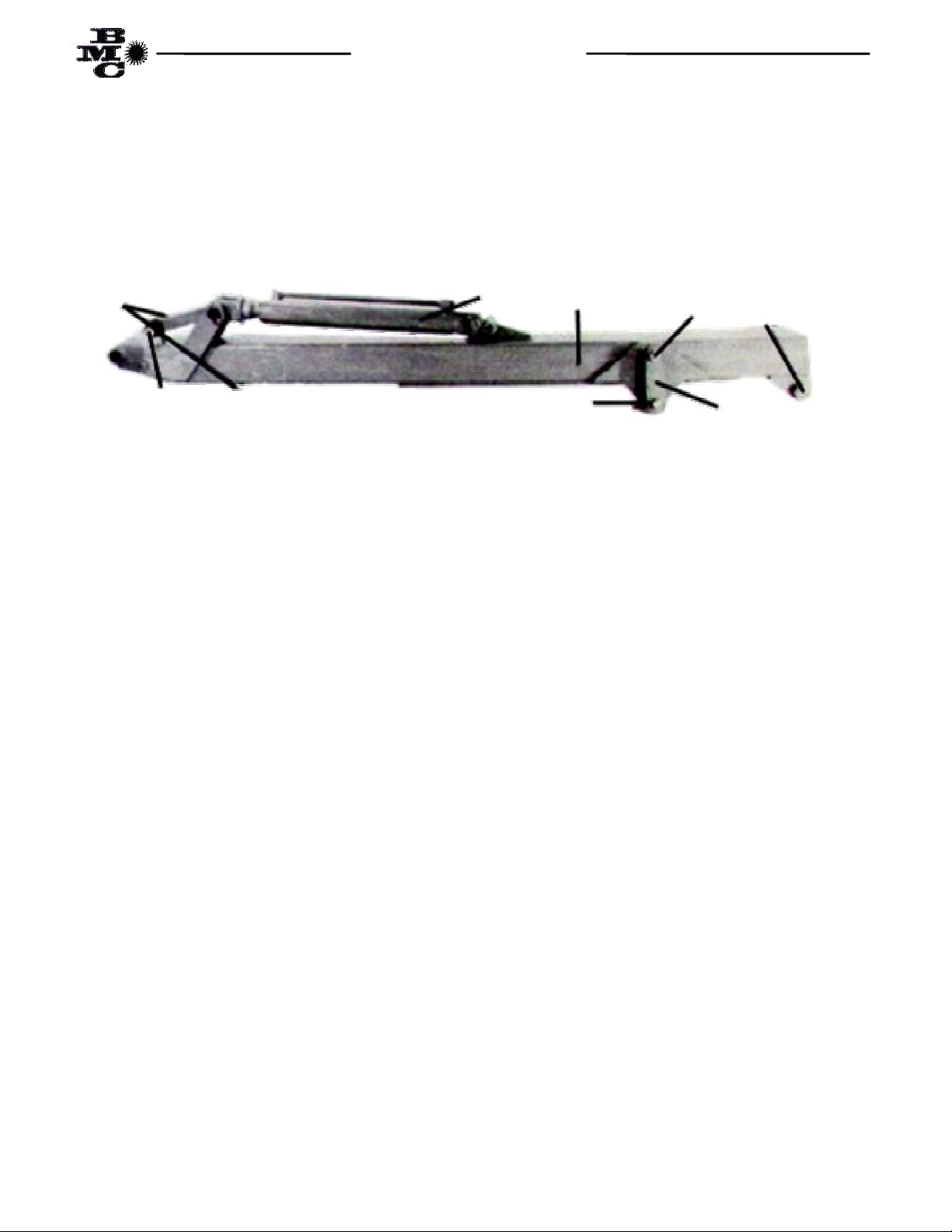
The BMC Series LD6, Fig 1. and MD8, Fig 2. Backhoes are shipped complete (crated) less mounting kit and
bucket. To mount either of the basic Backhoes to a tractor, a mounting kit (for a specific tractor model) is required.
Also required is one of the three bucket options for the LD6 and one of the four for the MD8. Items unique to each tractor fit
up (pressure / return hoses, seat assemblies, mounting bolts, etc.) are included in the mounting kit for each tractor.
The BMC Series LD6 and MD8 Backhoe can be installed from the crate to the tractor in a matter of a few hours. The
BMC Series Backhoes should be installed on tractors that have a front blade of front loader that will stabilize the
front of the tractor. Installation of the front blade or front loader is covered in the appropriate manual.
The LD6 and MD8 Backhoe general specifications are listed on page 41 and 42. The Backhoes are identified by name
plates as follows:
This manual is divided into five (5) major sections:
Installation of LD6 Backhoe (Page 6)
Installation of MD8 Backhoe (Page 1 )
Installation of Buckets (Page 20)
Hosing of the LD6 and MD8 Backhoe (Page 21)
Operation of the Backhoe (Page 26)
Maintenance of the Backhoe (Page 6)
The mounting frame, seat and backhoe / tractor hydraulic interface is covered in the mounting frame installation
sheet. During assembly and when ordering parts, the right side of the backhoe is the same as the right side of the
tractor, facing forward in the tractor operator’s seat.
Your local tractor and equipment dealer is responsible for the proper assembly and pre-delivery servicing of the
backhoe.
Bran ly Manufac uring Company reserves he righ o make design changes or improvemen s wi hou incurring any
obliga ion o up-da e exis ing equipmen or any obliga ion for no ifica ion o owners of exis ing equipmen of hose
changes.

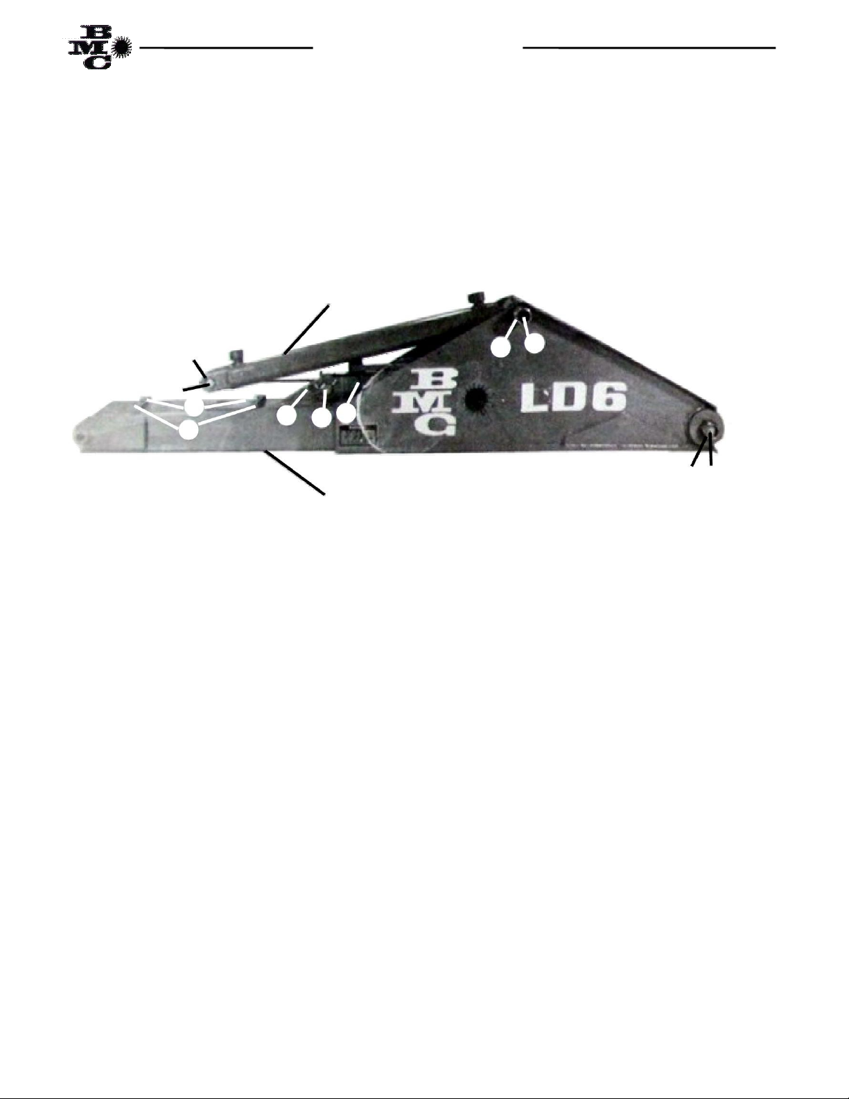
LD6 BACKHOE
3
Fig. 1
SERIES LD6 BACKHOE
1. Main Frame 8. Crowd Cylinder
2. Main Boom 9. Bucket Cylinder
. Dipper Arm 10. Control Valve
4. Bucket 11. Stabilizer Guard
5. Stabilizer Arm 12. Right Step
6. Stabilizer Cylinder 1 . Stabilizer Foot
7. Boom Cylinder 14. Grab Bar

MD8 BACKHOE
4
Fig. 2
SERIES MD8 BACKHOE
1. Main Frame 8. Crowd Cylinder
2. Main Boom 9. Bucket Cylinder
. Dipper Arm 10. Control Valve
4. Bucket 11. Stabilizer Guard
5. Stabilizer Arm 12. Right Step
6. Stabilizer Cylinder 1 . Stabilizer Foot
7. Boom Cylinder 14. Grab Bar
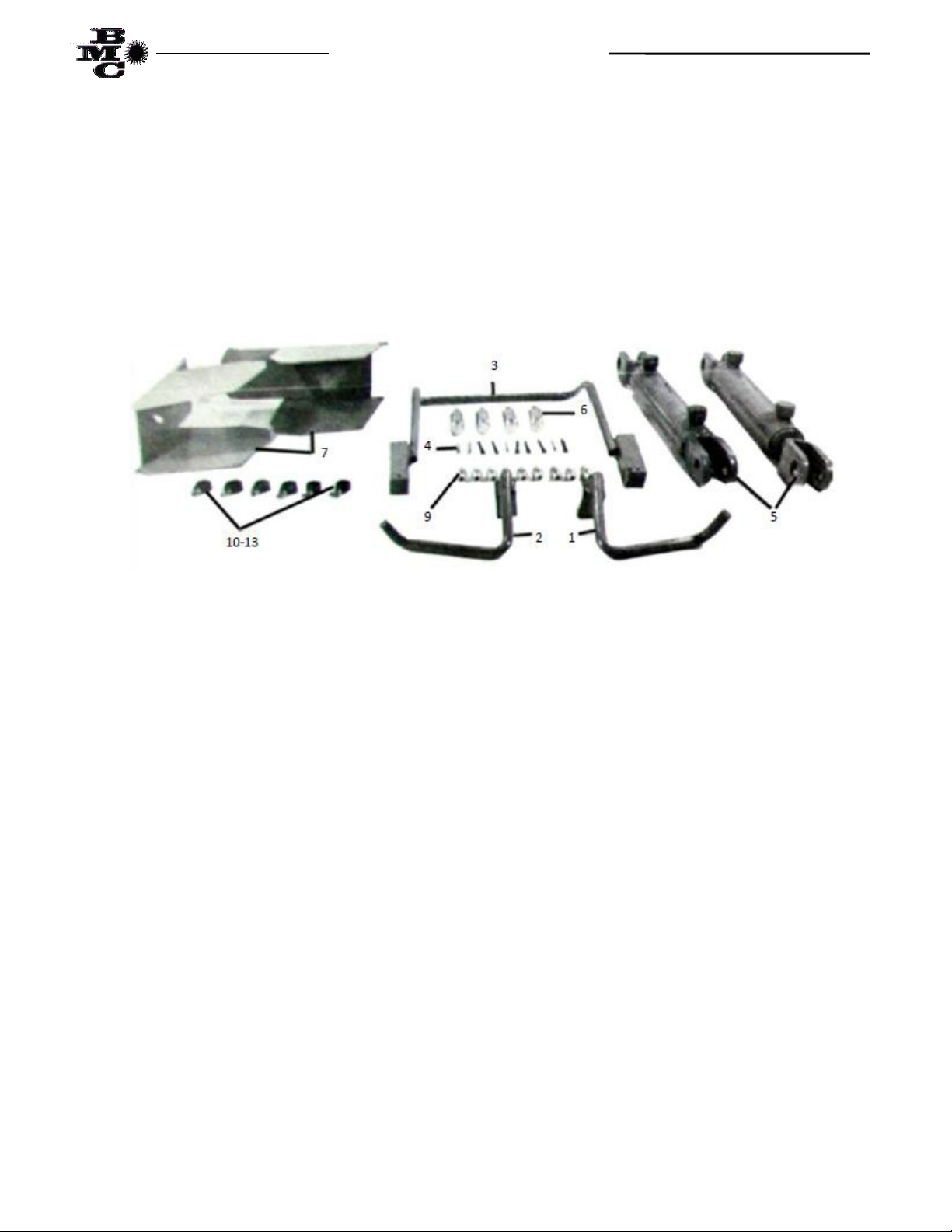
LD6 AND MD8 BACKHOE BOX PARTS
5
The LD6 and MD8 box parts contains items needed to complete the assembling of the LD6 and MD8 Backhoe. Be
sure to check the contents of the box against the packing list in the box or against the parts list in this manual.
Backhoe Box Par s
ITEM DESCRIPTION QUANTITY
1 Step, Right 1
2 Step, Left 1
Grab Bar 1
4 Cotter Pin /16” x 1 ½” 10
5 Cylinder, Stabilizer 2
6 Pin Cylinder 1” x ” 4
7 Guard, Stabilizer 2
8 Ties, Plastic Hose 5
9 Adaptor Fitting, SAE 6 O-Ring to JIC 6 Flare St. 10
10 Clamp, Insulated Hose 1” 6
11 Screw, Machine /16” x ¾” 6
12 Washer, Lock /16” 6
1 Nut, Hex /16” 6

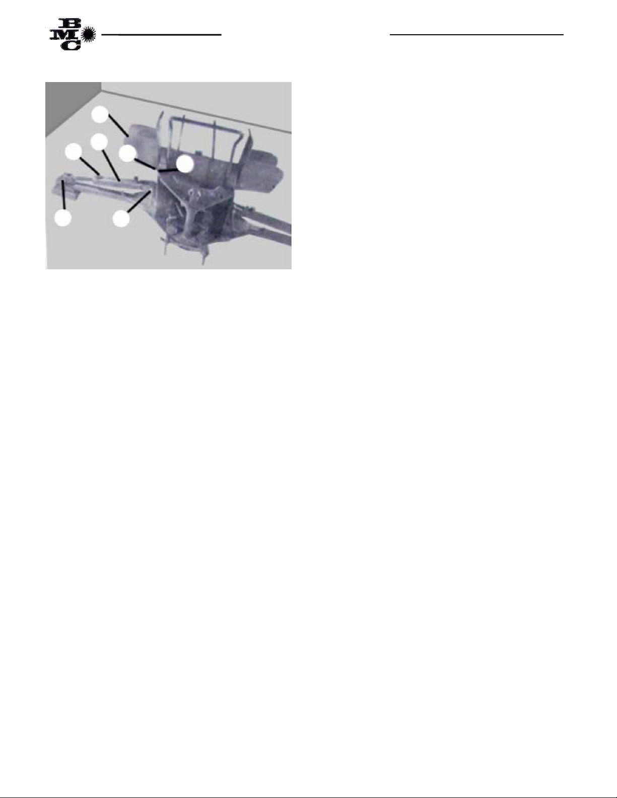
LD6 MAIN FRAME ASSEMBLY
6
Fig. 1
ITEM DESCRIPTION QUANTITY
1 Main Frame 1
2 *Step, Right 1
*Step, Left 1
4 *Grab Bar 1
5 Arm, Stabilizer 2
6 Pin, Stabilizer ¾” x 9 ½” 2
7 *Guard, Stabilizer 2
8 Pin, Stabilizer Guard ½” x 5” 2
9 *Cylinder, Stabilizer 2
10 *Pin, Cylinder 1” x ” 4
11 *Cotter Pin /16” x 1 ½” 14
12 Cotter Pin 1/8” x 1” 4
1 *Adaptor Fitting SAE 6 O-Ring to JIC 6 Flare Straight 4
14 *Ties, Plastic Hose 4
15 Bolt, Machine ¾” x 1 ½” G5P 1
16 Nut, Hex Self Locking ¾” 1
*ITEMS NOTED ARE SHIPPED IN BACKHOE PARTS BOX

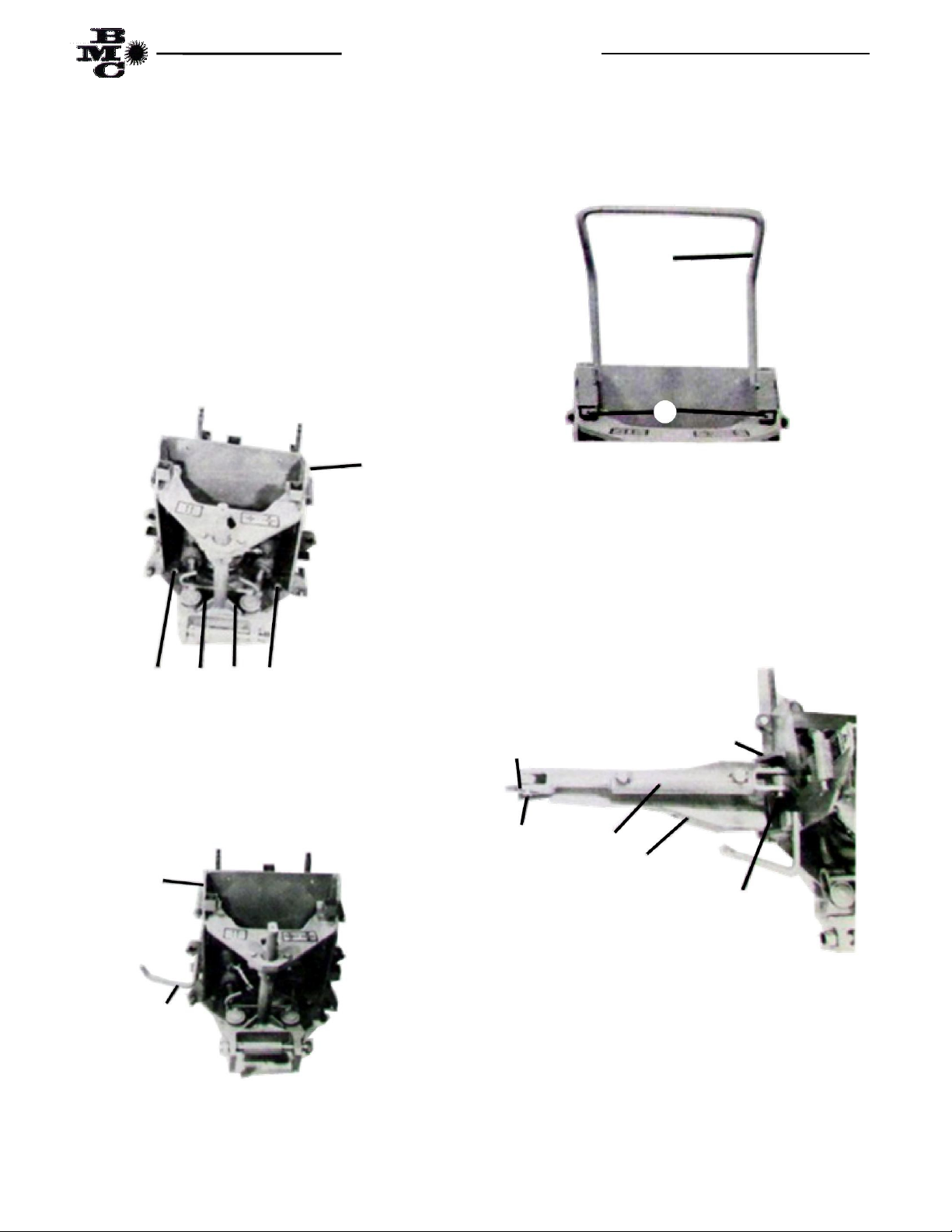
LD6 MAIN FRAME INSTALLATION
7
The LD6 main frame assembly, Fig 1, is shipped with
some of the retaining pins and bolts installed. It will be
necessary to remove the pins as the different parts are
assembled on the main frame. The main frame should
be installed on the mounting frame plate as follows:
(1) Position the Backhoe Mainframe (item 1) over the
Mounting plate on the Mounting Frame. Maneuver the
mainframe until the eight holes in the mainframe align
with the eight (8) holes in the mounting plate. Secure
the mainframe with eight (8) each 5/8” x 2” machine
bolts, lockwashers and hex nuts supplied in the
mounting frame kit. Torque the bolts and nuts per
Table 1, Page 9.
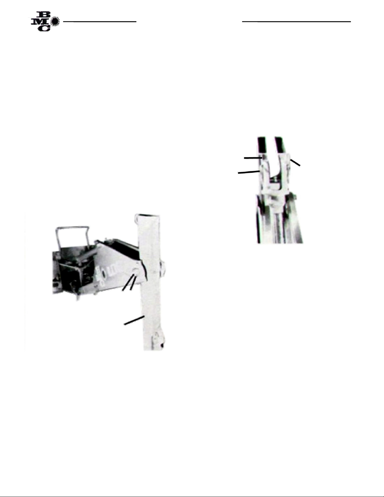
Fig. 2
(2) Install the left step (Item ) in the step mounting
receptacle located on the left side of the Backhoe main
frame with orientation of the step as shown in Fig. .
( ) Repeat step two to install the right step (Item 2).
Fig.
(4) Install the grab bar (Item 4) in the grab bar
mounting receptacle located on the inside of the side
plates and just above the top plate. Secure the grab bar
with two (2) /16” x 1 ½” cotter pins (Item 11) as
shown in Fig. 4.
Fig. 4
(5) Attach the left stabilizer arm (Item 5) between
the stabilizer mounting lugs, located on the left side of
the mainframe near lower edge, securing the arm to the
mainframe with one (1) each stabilizer pin (Item 6) and
two (2) each /16” x 1 ½” cotter pins as shown in Fig.
5.
(6) Repeat step 5 for the right side stabilizer arm.
Fig. 5
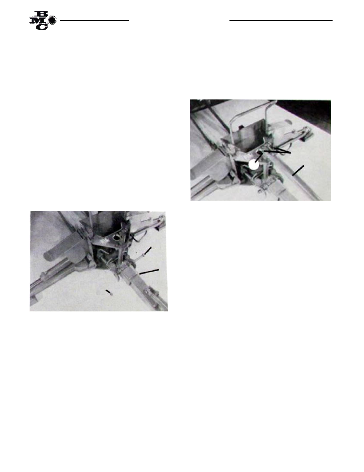
(7) Attach base end of (1) each stabilizer cylinder
(Item 9) to left side of main frame cylinder anchor lug,
located in the center and just above the base end of the
stabilizer arm, using one each cylinder pin (Item 10)
and two each /16” x 1 ½” cotter pins (Item 11) as
shown in Fig. 6.
Bolts Machine 5/8” x 2”
1
2
4
5 6 11
LD6 MAIN FRAME INSTALLATION
8
Fig. 6
(8) Attach the rod end of the stabilizer cylinder to the
anchor lug, located in the center of the stabilizer arm
near the stabilizer foot, using one each cylinder pin
(Item 10) and two each /16” x 1 ½” cotter pins (Item
11) as shown in Fig. 6.
(9) Attach the right side stabilizer cylinder by
repeating steps 7 and 8.
(10) Attach the left stabilizer guard (Item 7) over the
mounting receptacle, located on the upper portion of the
main frame side plate, aligning the two holes in the
stabilizer guard with the mounting receptacle and
inserting the guard pin (Item 8) through the guard and
receptacle. Secure the pin with two each 1/8” x 1”
cotter pins (Item 12) as shown in Fig. 6.
(11) Attach the right stabilizer guard by repeating
step 10.
(12) Install one each of the SAE 6 O-Ring to JIC 6
Flare Straight adapter fittings (Item 1 in box parts list,
page 5) in both ports of the right and left stabilizer
cylinders (four (4) required) as shown in Fig. 6.
NOTE: I is very impor an o check he orque on he eigh 5/8” x 2” machine bol s re aining he mainframe o he
moun ing frame op pla e af er eigh (8) hours of opera ion and every 40 hours of opera ion hereaf er. I is
accep able, once opera ion of backhoe and moun ing frame adap a ion o rac or has proved sa isfac ory, o weld he
mainframe o he moun ing ki .
7
10 10
1
12
8
9
LD6 MAIN BOOM ASSEMBLY
9
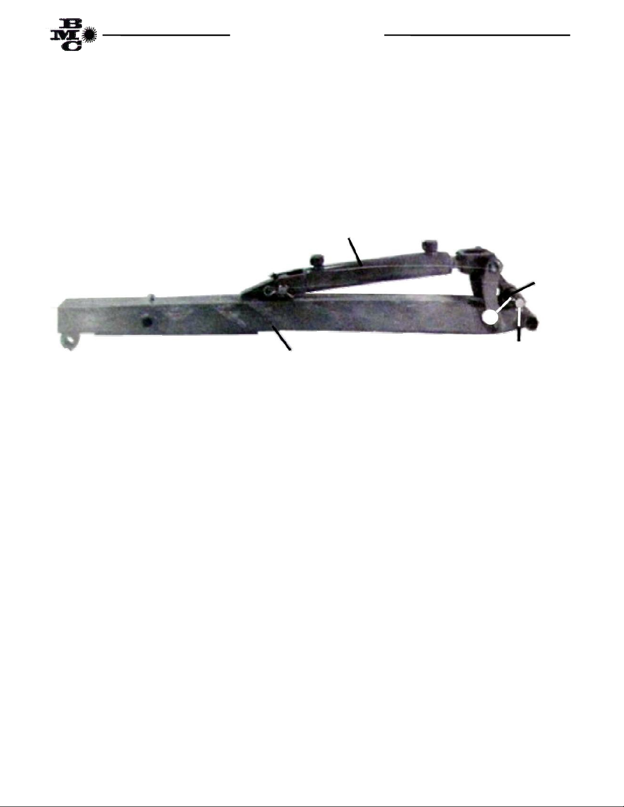
6
FIG. 1
ITEM DESCRIPTION QUANTITY
1 Main Boom 1
2 Cylinder, Main Boom 1
Pin, Cylinder ¾” x 2 ¾” 1
4 Cotter Pin 1/8” x 1” 2
5 Cylinder, Crowd 1
6 Pin, Cylinder 1” x ” 1
7 Clip, Bobby Pin 2
8 Bolt, Machine G5P 1” x 6 ½” 1
9 Nut, Self-Locking Hex 1” 2
10 Bolt, Machine 1” x 5 ½” 1
11 Clamp, Hose 4” 2
12 Bolt, Machine ¼” x 1 ¼” 2
1
2
4
9 8
10
9
11
12 7 5
LD6 MAIN BOOM INSTALLATION
10
The LD6 main boom assembly, Fig. 1, is shipped with
the retaining pins and bolts installed. It will be
necessary to remove the pins and bolts as the main
boom is being assembled to the main frame. The main
boom should be attached to the main frame as follows:
(1) Remove the ¾” x 10 ½” plated bolt (Item 15 in
the main frame assembly) and ¾” self-locking hex nut
(Item 16 in the main frame assembly) from the yoke of
the swing shaft. Position the base end of the main boom
(Item 1) between the mounting ears (use two men or
overhead hoist) and secure by re-inserting the ¾” x
10 ½” plated bolt through the yoke ear and boom as
shown in Fig. 2. The bolt should be seated (or
locked) in the locking ring on the outside mounting ear
of the yoke to prevent bolt from turning during
operation. Fasten the bolt in place with the ¾”
self-locking hex nut, tightening for fit but not
sufficiently to warp the yoke mounting ears.
Fig. 2
(2) Mount the base end of the main boom cylinder
(Item 2) with flat top end of the swing shaft between
the ears of the cylinder clevis. Secure the boom cylinder
with a ¾” x 2 ¾” cylinder pin (Item ) and two each
1/8” x 1” cotter pin (Item 4) as show in Fig. .
Fig.
( ) Install one each of the SAE 6 O-Ring to JIC 6 Flare
straight adapter fittings (Item 1 in box parts, Page 5) in
both ports of the crowd cylinder.
16
15
1
2
4
LD6 DIPPER ARM ASSEMBLY
11
FIG. 1
ITEM DESCRIPTION QUANTITY
1 Dipper (Crowd) Arm 1
2 Pin, Bucket Link 1” x 6 ¼” 1
Spacer, Bucket Link 1” I.D. x 1 ¼” O.D. x 2” 2
4 Cotter Pin /16” x 1 ½” 2
5 Cylinder, Bucket 1
1 2
4
5
LD6 DIPPER ARM INSTALLATION
12
The LD6 dipper arm (crowd) assembly, Fig. 1, is
shipped assembled with the exception of the adaptor
fittings and the retaining pin and bolt. The retaining
bolt and pin are shipped installed in the main boom
assembly. Attach the dipper arm to the main boom in
the following manner:
(1) Remove the 1” x 6 ½” plated bolt (Item 8 in the
main boom assembly) from the main boom. Using an
overhead hoist, raise the main boom until the dipper
arm (Item 1) can be inserted between the side plates on
the top end of the main boom as shown in Fig. 2. Re-
insert the 1” x 6 ½” plated bolt from the left side
through the boom and the dipper arm. Secure the bolt
with a 1” self-locking hex nut (Item 9 in the main boom
assembly).
Fig. 2
(2) Raise rod end of dipper (crowd) cylinder and slide
the cylinder clevis astraddle the top anchor lug on the
dipper arm as shown in Fig. . Secure the cylinder to
the dipper arm with a 1” x ” cylinder pin (Item 6 in the
main boom assembly) and two each bobby pin clips
(Item 7 in the main boom assembly).
Fig.
( ) Install one each of the SAE 6 O-Ring to JIC 6 Flare
straight adapter fittings (Item 1 in box parts) into each
of the ports of the bucket cylinder (Item 5).
1
8 9
7
7
6

MD8 MAIN FRAME ASSEMBLY
13
Fig. 1
ITEM DESCRIPTION QUANTITY
1 Main Frame 1
2 *Step, Right 1
* Step, Left 1
4 *Grab Bar 1
5 Arm, Stabilizer 2
6 Pin, Stabilizer Arm ¾” x 9 ½” 2
7 *Guard, Stabilizer 2
8 Pin, Stabilizer Guard ½” x 5” 2
9 *Cylinder, Stabilizer 2
10 *Pin, Cylinder 1” x ” 4
11 *Cotter Pin /16” x 1 ½” 14
12 Cotter Pin 1/8” x 1” 4
1 *Adaptor Fitting SAE 6 O-Ring to JIC 6 Flare Straight 4
14 *Ties, Plastic Hose 4
15 Bolt, Machine G5P 1” x 10 ½” 1
16 Nut, Hex Self-Locking 1
17 Spacer 1” I.D. x 1 5/16” O.D. x 5” 1
*ITEMS NOTED ARE SHIPPED IN BACKHOE PARTS BOX
1
8
8
5
5
15 6
6
17 16
MD8 MAIN FRAME INSTALLATION
14
The MD8 main frame assembly, Fig 1, is shipped with
some of the retaining pins and bolts installed. It will be
necessary to remove the pins as the different parts are
assembled on the main frame. The main frame should
be installed on the mounting frame plate as follows:
(1) Position the Backhoe Mainframe (item 1) over the
mounting plate on the mounting Frame. Maneuver the
main frame until the eight holes in the main frame
align with the eight (8) holes in the mounting plate.
Secure the mainframe with eight (8) each 5/8” x 2”
machine bolts, lockwashers and hex nuts supplied in
the mounting frame kit. Torque the bolts and nuts per
Table 1, Page 9.
Fig. 2
(2) Install the left step (Item ) in the step mounting
receptacle located on the left side of the Backhoe main
frame with orientation of the step as shown in Fig. .
( ) Repeat step two to install the right step (Item 2).
Fig.
(4) Install the grab bar (Item 4) in the grab bar
mounting receptacle located on the inside of the side
plates and just above the top plate. Secure the grab bar
with two (2) /16” x 1 ½” cotter pins (Item 11) as
shown in Fig. 4.
Fig. 4
(5) Attach the left stabilizer arm (Item 5) between
the stabilizer mounting lugs, located on the left side of
the mainframe near lower edge, securing the arm to the
mainframe with one (1) each stabilizer pin (Item 6) and
two (2) each /16” x 1 ½” cotter pins as shown in Fig.
5.
Fig. 5
(6) Repeat step 5 for the right side stabilizer arm.
1
Bolts, Machine 5/8” x 2”
1
2
11
10 9
5
10
6
4
11

MD8 MAIN FRAME INSTALLATION
15
(7) Attach base end of one (1) each stabilizer cylinder
(Item 9) to left side of main frame cylinder anchor lug,
located in the center and just above the base end of the
stabilizer arm, using one each cylinder pin (Item 10)
and two each /16” x 1 ½” cotter pins (Item 11) as
shown in Fig. 5.
(8) Attach the rod end of the stabilizer cylinder to the
anchor lug, located in the center of the stabilizer arm
near the stabilizer foot, using one each cylinder pin
(Item 10) and two each /16” x 1 ½” cotter pins (Item
11) as shown in Fig. 5.
(9) Attach the right side stabilizer cylinder by
repeating steps 7 and 8.
(10) Attach the right stabilizer guard (Item 7) over the
mounting receptacle, located on the upper portion of
the main frame side plate, aligning the two holes in the
stabilizer guard with the mounting receptacle and
inserting the guard pin (Item 8) through the guard and
receptacle. Secure the pin with two each 1/8” x 1”
cotter pins (Item 12) as shown in Fig. 6.
Fig. 6
(11) Attach the left stabilizer guard by repeating
step 11.
(12) Install one each of the SAE 6 O-Ring to JIC 6
Flare Straight adaptor fittings (Item 1 in box parts list,
page 5) in both ports of the right and left stabilizer
cylinders (four (4) required) as shown in Fig. 6.
NOTE: I is very impor an o check he orque on he eigh 5/8” x 2” machine bol s re aining he mainframe o he
moun ing frame op pla e af er eigh (8) hours of opera ion and every 40 hours of opera ion hereaf er. I is
accep able, once opera ion of backhoe and moun ing frame adap a ion o rac or has proved sa isfac ory, o weld he
mainframe o he moun ing ki .
1
7
8
9
12

MD8 MAIN BOOM ASSEMBLY
16
6
FIG. 1
ITEM DESCRIPTION QUANTITY
1 Main Boom 1
2 Cylinder, Main Boom 1
Pin, Cylinder ¾” x 2 ¾” 1
4 Cotter Pin 1/8” x 1” 2
5 Cylinder, Crowd 1
6 Bolt, Machine 1” x 6 ½” 1
7 Nut, Self-Locking 1” 1
8 Clamp, Hose 4” 2
9 Bolt, Machine ¼” x 1 ¼” 2
2
9
8
7
1

MD8 MAIN BOOM INSTALLATION
17
The MD8 main boom assembly, Fig. 1, is shipped with
the retaining pins and bolts installed. It will be
necessary to remove the pins and bolts as the main
boom is being assembled to the main frame. The main
boom should be attached to the swing shaft as follows:
(1) Remove the 1” x 10 ½” plated bolt (Item 15 in the
main frame assembly) and the 1” I.D. x 1 5/16” O.D. x
5” spacer (Item 17 in the main frame assembly) from
the yoke of the swing shaft. Position the base end of the
main boom (Item 1) between the mounting ears (use two
men or overhead hoist) and insert the spacer
between the boom swivel lugs. Re-insert the 1” x
10 ½” plated bolt through the yoke ears, spacer and the
boom swivel lugs as shown in Fig. 2. The head of the
bolt should be seated (or locked) against the shoulder
on the outside surface of the mounting ears to prevent
the bolt from turning during operation. Fasten the bolt in
place with the 1” self-locking hex nut and tighten for
tight fit but not sufficiently to warp the yoke mounting
ears.
Fig. 2
(2) Mount the base end of the main boom cylinder (Item
2) with flat top end of the swing shaft between the ears
on the cylinder clevis. Secure the cylinder with the ¾”
x 2 ¾” cylinder pin (Item ) and two cotter pins (Item 4)
as show in Fig. .
Fig.
( ) Install one each of the SAE 6 O-Ring to JIC 6 Flare
Straight adapter fittings (Item 1 in box parts list, page
5) in both ports of the crowd cylinder.
1
17 15
4
2
MD8 DIPPER ARM ASSEMBLY
18
FIG. 1
ITEM DESCRIPTION QUANTITY
1 Dipper (Crowd) Arm 1
2 Pin, Locking Arm 1” x 7 7/8” 1
Plate, Locking Pin 1
4 Bolt, Machine G5P ½” x 1 ½” 1
5 Washer, Lock ½”
6 Spacer, Locking Pin 1” I.D. x 1 ¾” O.D. x 1/8” 2
7 Spacer, Locking Pin ½” I.D. x 1” O.D. x 1 ¼” 2
8 Bolt, Machine G5P ½” x 2 ¼” 2
9 Bolt, Machine G5P 1” x 4 ½” 1
10 Nut, Self-Locking Hex 1” 1
11 Cylinder, Bucket 1
12 Pin, Bucket Link 1” x 6 ¼” 1
1 Spacers, Bucket Link 1” I.D. x 1 ¼” O.D. x 2” 2
14 Cotter Pin /16” x 1 ½” 2
1
12
4
9, 10 8
11
1
14
This manual suits for next models
1
Table of contents


