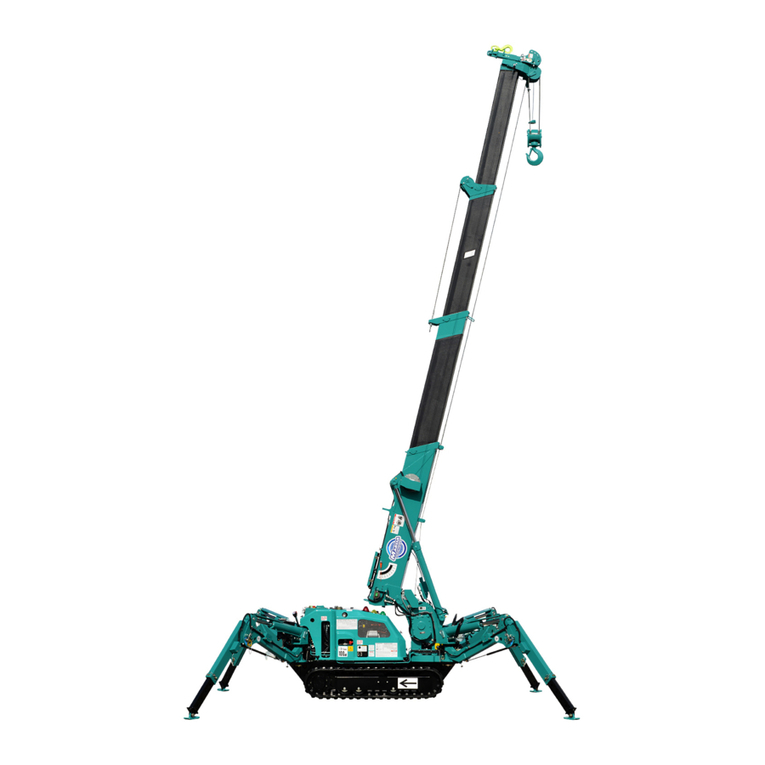
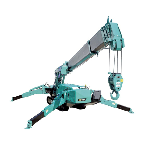
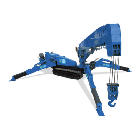
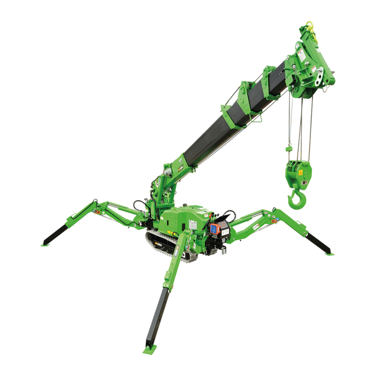
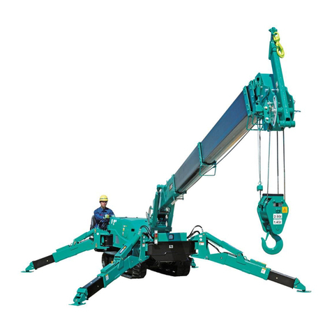
Maeda MC174 User manual

OPERATOR MANUAL
MAEDA MC174
300KG - SEARCHER HOOK
www.hird.co.uk
DISCLAIMER - ALL INSTRUCTIONS ARE SUPPLIED FROM MANUFACTURER AND WHERE CORRECT AT TIME OF PRINT
Northern (Head Office)
Tel: +44 (0)1482 227333
Western
Tel: +44 (0)1384 900388
Southern
Tel: +44 (0)203 174 0658
Central
Tel: +44 (0)1302 341659

CONTENTS
ITEM Page
1. INTRODUCTION 1
2.FOR SAFE USE OF MACHINE 2
3. SAFETY DECAL LOCATIONS 3
4. SEARCHER HOOK EACH SECTION 5
5. NAMES OF MOMENT LIMITER DISPLAY UNIT 7
6. OPERATION 9
7. INSPECTION AND MAINTENANCE 11
7.1 LEGAL INSPECTION 11
7.2 CONSUMABLES 11
7.3 INSPECTION AND MAINTENANCE LIST 11
7.4 MAINTENANCE PROCEDURES 12
7.4.1 INSPECTION BEFORE OPERATION 12
8. WORKING RANGE AND RATED TOTAL LOAD 14
8.1 WORKING RANGE DIAGRAM FOR SEARCHER HOOK 14
8.2 RATED TOTAL LOAD CHART FOR SEARCHER HOOK 15

- 1 -
1. INTRODUCTION
Thank you for purchasing the “Searcher Hook” for MAEDA Mini Crawler Crane model
MC-174C.
This manual is intended as a guide for the safe and effective use of this machine.
This manual describes the procedures for proper operation and maintenance of the machine.
Warnings and precautions defined in this manual shall be observed for safety.
Many of the accidents are caused by the operation, inspection, or maintenance that does not
observe the basic precautions.
Be sure to read this manual and understand the procedures for machine operation,
inspection, and maintenance thoroughly before performing operation of this machine.
Failure to observe the basic precautions defined in this manual may lead to hazardous
accidents.
Failure to use this machine properly can lead to serious personal injury or death.
Operators and maintenance personnel must always read this manual prior to
operation or maintenance of this machine.
Save this manual at a designated place for reference when necessary. All personnel
who work on this machine are to carry out periodic reference.
•Only those who have thorough understanding of the fundamental procedures
provided in this manual are qualified to perform machine operation.
•Keep this manual handy for reference when necessary.
•Should you lose or damage this manual, contact Maeda or our sales service
agency immediately for ordering a new manual.
•This manual should always accompany this machine upon transfer of the machine
to the next owner.
•This manual has adopted data that was available at the time of the creation of the
manual.
The contents of this manual, including maintenance specifications, tightening
torque, pressure, measuring method, adjustment value, and illustrations, are
subject to change upon unremitting refinement of the machine, without notice.
Machine maintenance may be susceptible to revisions. Always obtain the latest
information from Maeda or our sales service agency before performing
maintenance of this machine.
For safety instructions, see “2. For Safe Use of Machine” on page 2.
- 2 -
2. FOR SAFE USE OF MACHINE
This manual classifies the risks into the following three categories to present the details of the safety
labels in easy-to-understand manner.
This denotes that there is an imminent hazard which will cause serious
personal injury or death.
The method of hazard circumvention is stated.
This denotes that there is a hazard which can cause serious personal
injury or death.
The method of hazard circumvention is stated.
This denotes that there is a potential hazard which may cause minor or
moderate personal injury or serious damage to this machine.
The method of hazard circumvention is stated.
This manual also provides the following to indicate what must be observed for the sake of the machine
and what will be of help.
CAUTION This denotes that failure to handle the machine properly may damage
the machine or shorten its life.
NOTES This denotes helpful information.
Not only procedures for operation, inspection, and maintenance of this machine described in this manual
but also safety precautions should pertain to the case where this machine is only used for specified tasks.
Every circumstance incidental to use of this machine is unforeseeable, and therefore, cautions given in
this manual and on this machine do not necessarily cover every safety-related issue.
Necessary safety actions should be taken under your responsibility if operation, inspection, and
maintenance in a situation that is not described in this manual are performed.
Even in the above case, never attempt work and operations that this manual prohibits you to do.

- 3 -
3. Safety Decal Locations

- 4 -
①102-4608500
②101-4608700
③101-3327300
④101-4609300

- 5 -
4. Searcher Hook Each Section
6
(1) Hook
(2) E-Boom
(3) Bracket
(4) Position pin
(5) Snap pin
(6) Hex. head bolt
(7) High tension washer
(8) Hex. head nut

- 6 -
6
(9) Moment limiter Display unit (10) Boom lift bypass switch

- 7 -
5. NAMES OF MOMENT LIMITER DISPLAY UNIT
(1) Boom angle display
(2) Lifting height display
(3) Boom length display
(4) Boom lifting height upper limit LED (Red)
(5) Boom lifting height upper limit switch
(6) Boom angle lower limit LED (Red)
(7) Boom angle lower limit switch
(8) Over hoist detection LED (Red)
(9) Actual load display
(10) Rated total load display
(11) Working radius upper limit LED (Red)
(12) Working radius upper limit switch
(13) Working radius display
(14) Boom angle upper limit LED (Red)
(15) Boom angle upper limit switch
(16) Outrigger MIN. extension LED (Orange)
(17) Outrigger MID. extension LED (Orange)
Not in use MC-174C.
(18) Outrigger MAX. extension LED (Orange)
(19) Check switch
(20) Cancel switch
(21) Load capacity less than 70% LED (Orange)
(22) Load capacity 70 to less than 100% LED
(Orange)
(23) Load capacity 100% or more LED (Orange)
(24) 1-fall LED (Orange)
(25) 2-fall LED (Orange)
(26) 4-fall LED (Orange)
(27) Fall mode selector switch
For general operation, see “Moment Limiter (Overload Detector) in the MC-174C Operation Manual
page 3-16”.

- 8 -
[1] DESCRIPTIONS OF SWITCHES ON MOMENT LIMITER DISPLAY UNIT
CAUTION
Refer “Moment Limiter (Overload Detector) in the MC-174C Operation Manual page 3-16”
section for switches other than the “WIRE FALLS SELECTOR SWITCH AND WIRE AND WIRE
FALLS DISPLAY LED” shown in the next section.
1. WIRE FALLS SELECTOR SWITCH AND WIRE FALLS DISPLAY LED (BLUE)
Fall mode must be set as “Searcher hook mode” when operating searcher hook. Using
searcher hook other than in “Searcher hook mode” may prevent issuance of the pre-warnings
and boom auto-stop even when the overload is near happening, and thus may result in crane
damage or the machine tripping over and may result in a serious accident.
Use this switch to change the number of wire falls.
•Keep pressing the switch for 2 seconds or more.
The setting changes from “4-falls” to “Searcher hook mode”. At
the same time, the wire falls display LED changes from “4-falls”
to “Searcher hook mode (all lights ON)”, indicating that the
setting has changed.
• Then each time you press the switch for 2 seconds or more, the
setting of the wire falls changes from “Searcher hook mode” to
“1-fall”, then “1-fall” to “2-falls”, and then “2-falls” to “4-falls”.
NOTES
When changing the setting right after doing so, release your
hand from the switch, and then press the switch again.

- 9 -
6. Operation
1. See “Outrigger Setting in the MC-174C Operation Manual,
page 3-68” and set the outrigger.
2. Fasten searcher bracket (3) to main-boom using 4 sets of M12
bolts and nuts. Tighten the bolts with torque wrench (B) then to
torque of 93Nm [±13Nm].
Torque Searcher Hook mounting plate bolts to 93Nm.
Use new nuts, bolts and washers every time mounting plate
is installed.
Refer to the Operation Manual for complete details.
3. Shift the wire falls selector switch on moment limiter display
unit to ”Searcher hook mode” (all LED ON).
Fall mode must be set as “Searcher hook mode” when
operating searcher hook. Using searcher hook other than
in “Searcher hook mode” may prevent issuance of the
pre-warnings and boom auto-stop even when the overload
is near happening, and thus may result in crane damage or
the machine tripping over and may result in a serious
accident.
4. Remove the snap pin (5) from the end of position pin (4) of
bracket (3), and remove the position pin (4).
5. Move E boom (2) to the required angle for the work, and line
up the holes in the E boom (2) and bracket (3).

- 10 -
6. Insert the position pin (4) through the hole of bracket (3), and
secure it with the snap pin (5) to the tip of position pin (4).
Always secure the position pin (4) with the snap pin (5). If
the snap pin falls out during operations, serious injury or
damage to the machine may result.
7. Attach the load securely to the hook (1) and start operations.
Always work in accordance with all appropriate local
regulations concerning your own and others’ safety.
8. In case machine is automatically stopped in overload condition,
boom can be lifted using the boom lift by-pass switch (6).
To operate boom lifting using this boom lift bypass
switch(6),keep pressing the switch to upper side and operate
boom lift at the same time.
After the work, release the switch and it automatically turns off.
The boom lift bypass switch is to be used only when in
searcher hook mode.
The boom lift function is stopped automatically when
overloaded.
Use this switch to enable the boom lift function for safety.
This switch is for emergency use only, never use this for
normal lifting of loads clear of ground.
NOTES
In case machine is automatically stopped by entering overload area
by boom lowering or boom extending operation, recover from the
overload area by retracting boom, or lifting boom by keeping the
boom lift by-pass switch to ON side.
NOTES
When working envelope is set, and operation automatically stops at
the boom upper angle limit or hook height upper limit, boom can be
lifted beyond the limit by using this boom lift bypass switch.
The boom lift bypass switch is to be used only when in searcher
hook mode.
XAM29050 新規

- 11 -
7. Inspection and Maintenance
7.1 Legal Inspection
If a periodic safety inspection is required by the laws and regulations of your country, perform that
inspection in addition to the inspection items listed below.
1. Verify that all safety devices are operating properly.
2. Check the hoist accessories, including the hook block, for problems or damage.
3. Check the structural parts of the machine, including the frame and boom, for cracks, deformation and
damage.
4. Check for loose or missing mounting bolts and joints.
5. Verify that the boom operates properly by stopping, extending, retracting, raising, lowering and
swinging the boom.
Contact Maeda or a Maeda sales service agency to request inspection and repair service as needed.
7.2 Consumables
Parts for mounting searcher hook are consumption articles. Replace it at periodic inspection or before it
reaches abrasion limits. Replace consumption articles regularly, which shall produce economical use of
this machine. Always replace to our genuineitem. Check parts catalog for correct part number for parts
request.
[CONSUMABLES LIST]
Part Replacement cycle
Searcher hook fix bolt M12x35L (4pcs) Every 6 months or when damage, crack, or squash is
found
Searcher hook fix nut
M12x1grade (4pcs) Every 6 months or when damage, crack, or squash is
found
Searcher hook fix washer
M12x3.2t (high tension)(8pcs) Every 6 months or when damage, crack, or squash is
found
Items include a halt period. Contact Maeda or a Maeda sales service agency for part replacement
information.
7.3 Inspection and Maintenance List
This section only covers searcher hook kit. For crane body, please refer to “Inspection and Maintenance
in the MC-174C Operation Manual” and follow its precautions.
Inspection and maintenance items Page
7.4.1 INSPECTION BEFORE OPERATION 14
[CHECKING BEFORE STARTING ENGINE] 14
[1] CHECKING BOOM AND BRACKET 14
[2] CHECKING SEARCHER HOOK FIX BOLTS 14
[3] CHECKING ELECTRICAL WIRING FOR DAMAGE 14
[CHECKING AFTER STARTING ENGINE] 15
[1] CHECKING FUNCTIONS OF BOOM 15
[2] CHECKING MOMENT LIMITER FOR OPERATION (SEARCHER HOOK MODE) 15

- 12 -
7.4 Maintenance Procedures
7.4.1 Inspection Before Operation
[CHECKING BEFORE STARTING ENGINE]
Check the following in this section without starting the engine and before starting the first work every
day.
[1] CHECKING BOOM AND FRAME
• Check each part of the boom and frame for cracks, excessive deformation, contamination and other
damage. In addition, check bolts, nuts and pins for any looseness, drop, damage and other matters. If
you find any abnormality, repair.
[2] CHECKING SEARCHER HOOK FIX BOLTS
If any damage found on searcher hook fix bolt, please exchange it to new one right away.
Breakage of bolt cause searcher hook to fall off.
• Check if there is crack, damage, or squash on screw thread on screw part of bolt.
If crack, damage or squash on screw thread is found, change the bolt to new one even if it is earlier
than expected bolt life.
[3] CHECKING ELECTRICAL WIRING (FUSE BOX) FOR DAMAGE
If fuses are blown frequently or if you find the trace of a short circuit created in the electrical
wiring, be sure to find the cause and fix the problem.
1. Turn the fuse holders on control panel counterclockwise and
take tubular fuses out.
2. Check the fuse for damage andmeltdown and if thefuse of the
specified capacity is being used.
3. If a fuse has melted down or the trace of an open/short circuit
is found in the electrical wiring, ask us or our sales service
agency for repair.

- 13 -
[CHECKING AFTER STARTING ENGINE]
Check the following in this section after starting the engine and before starting the first work every day.
CAUTION
The checkups described in this section should be carried out after starting the machine.
Refer to "Starting the Engine in the MC-174C Operation Manual page 3-54" and later to execute
the engine startup, traveling operations, outrigger operations and crane operations.
[1] CHECKING FUNCTIONS OF BOOM
At the performance of function check for boom, ensure the safety so that hook and boom do not
interfere with any personnel or object.
1. Check abnormal noise from boom and searcher hook during
crane operation.
2. Operate crane without load and check each bolt so that no one
is missing or loose.
3. Check hook for deformation, abnormal noise from bearing and
correct function of wire rope latch (1).
[2] CHECKING MOMENT LIMITER FOR OPERATION (SEARCHER HOOK MODE)
If you find any abnormality with the moment limiter, immediately contact us or our sales service
agency.
1. Turn the starter switch to the “ON” position.
2. Check with the working status lamp. The red of the lamp lights up for 2 seconds and then the green
lights up.
3. Check the moment limiter display unit.
Verify that no error codes are displayed on the “RATED TOTAL LOAD” display.
4. Shift the fall mode selector switch on moment limiter display unit to ”Searcher hook mode” (all LED
ON).
5. Start the engine and operate the crane as follows to verify that the moment limiter properly displays
the value.
Crane Operation and Displayed Parameter Value Displayed on
Moment Limiter
Displayed “boom length” with the boom length at minimum 1.8 m
Displayed “boom length” with the boom length at maximum 5.5 m
Displayed “working radius” with the boom length of “2.9 m” and boom angle of
“55.5 °“ 1.5 ± 0.1 m
Displayed “ACTUAL LOAD” when the weight of the known weight was hoisted
Must be equal to the total weight of weight + lifting ring
Note that it may show some errors depending on the boom conditions.
Actual load
6. Operate the crane until the moment limiter display indicates the boom length is "2.9 m" (booms (1) +
(2)) and boom angle is "55.5 degrees", then measure the "boom angle" and "working radius.
If the measured value(s) differ from the moment limiter display value, contact MAEDA or MAEDA
sales agency.

- 14 -
8. Working Range and Rated Total Load
•When using the searcher hook, be sure to set searcher hook mode for moment limiter.
•Never use the searcher hook and the crane hook simultaneously.
8.1 Working Range Diagram for Searcher Hook

- 15 -
8.2 Rated Total Load Chart for Searcher Hook
Rated total load Chart with outrigger extended to maximum
1.830m BOOM 2.965m BOOM 4.205m BOOM 5.445m BOOM
Working
radius (m)
Rated
total load
(kg)
Working
radius (m) Rated total
load (kg) Working
radius (m) Rated total
load (kg) Working
radius (m)
Rated
total load
(kg)
Less than
1.00 300 Less than
1.00 300 Less than
1.30 300 Less than
1.70 300
1.30 300 1.30 300 1.50 300 2.00 300
1.55 300 1.50 300 2.00 300 2.50 300
-- -- 2.00 300 2.50 300 2.80 300
-- -- 2.50 300 3.00 300 3.00 300
-- -- 2.69 300 3.50 300 3.50 300
-- -- -- -- 3.93 300 4.00 250
-- -- -- -- -- -- 4.50 200
-- -- -- -- -- -- 5.17 150
Rated total load Chart with outrigger extended to other than maximum
1.830m BOOM 2.965m BOOM 4.205m BOOM 5.445m BOOM
Working
radius (m)
Rated
total load
(kg)
Working
radius (m) Rated total
load (kg) Working
radius (m) Rated total
load (kg) Working
radius (m)
Rated
total load
(kg)
Less than
1.00 300 Less than
1.00 300 Less than
1.30 300 Less than
1.70 300
1.30 300 1.30 300 1.50 300 2.00 300
1.55 300 1.50 300 2.00 300 2.50 300
-- -- 2.00 300 2.50 300 2.80 250
-- -- 2.50 300 3.00 250 3.00 250
-- -- 2.69 300 3.50 150 3.50 150
-- -- -- -- 3.93 100 4.00 100
-- -- -- -- -- -- 4.50 50
-- -- -- -- -- -- 5.17 50
1. This Rated Total Load Chart shows maximum allowable capacities. These rated total loads are based on
the machine standing level on a firm ground supporting surface, under ideal job conditions and a freely
suspended load.
2. Sufficient design tolerance must be used to ensure adequate ground support surface design. The rated
total loads are for static conditions only, and do not include dynamic effects of swinging , extending,
retracting, lowering, raising, wind or adverse conditions. Crane users must reduce rated total loads ratings
to take all conditions into account.
3. The load radius shown in the Rated Total Load Chart is based on practical working radius including boom
deflection due to loading. The crane user must calculate and compensate for boom deflection as the load is
lifted.
4. Deductions from Searcher Hook Rated Total Load must be made for the weight of the searcher hook
(10kg), block/ball and all rigging.
5. Crane users must consult the Operators Manual for complete details about assembly, operation,
maintenance, configuration, and its limitations. Modifications to the crane, other than what is specified or
supplied by the original equipment manufacture, can result in a reduction of rated total load ratings.
6. This operating range chart does not include boom deflections.
Table of contents
Other Maeda Construction Equipment manuals

Maeda
Maeda MC285C-2 User manual

Maeda
Maeda MC815C User guide

Maeda
Maeda LC1385M-8BF User manual

Maeda
Maeda MC-174CRM User guide

Maeda
Maeda MC-285C User guide

Maeda
Maeda MC305C-3 User manual

Maeda
Maeda MC285C-3 User manual

Maeda
Maeda MC-305C-2 User guide

Maeda
Maeda MC-174CRM User manual

Maeda
Maeda CC1485S-1 Installation manual

Maeda
Maeda LC1385M-8B User manual

Maeda
Maeda LC785M-6B User manual

Maeda
Maeda HIRD MC815 User manual

Maeda
Maeda MK1033C-1 User manual

Maeda
Maeda LC785M-8B User manual

Maeda
Maeda CC423S-1 User manual

Maeda
Maeda CC1908S-1 User manual

Maeda
Maeda CC1485S-1 User guide

Maeda
Maeda LC383M-5 User manual

Maeda
Maeda MC285C-3 User manual