ELECRAFT AX Series User manual

1
ELECRAFT AX-LINE OWNER’S MANUAL
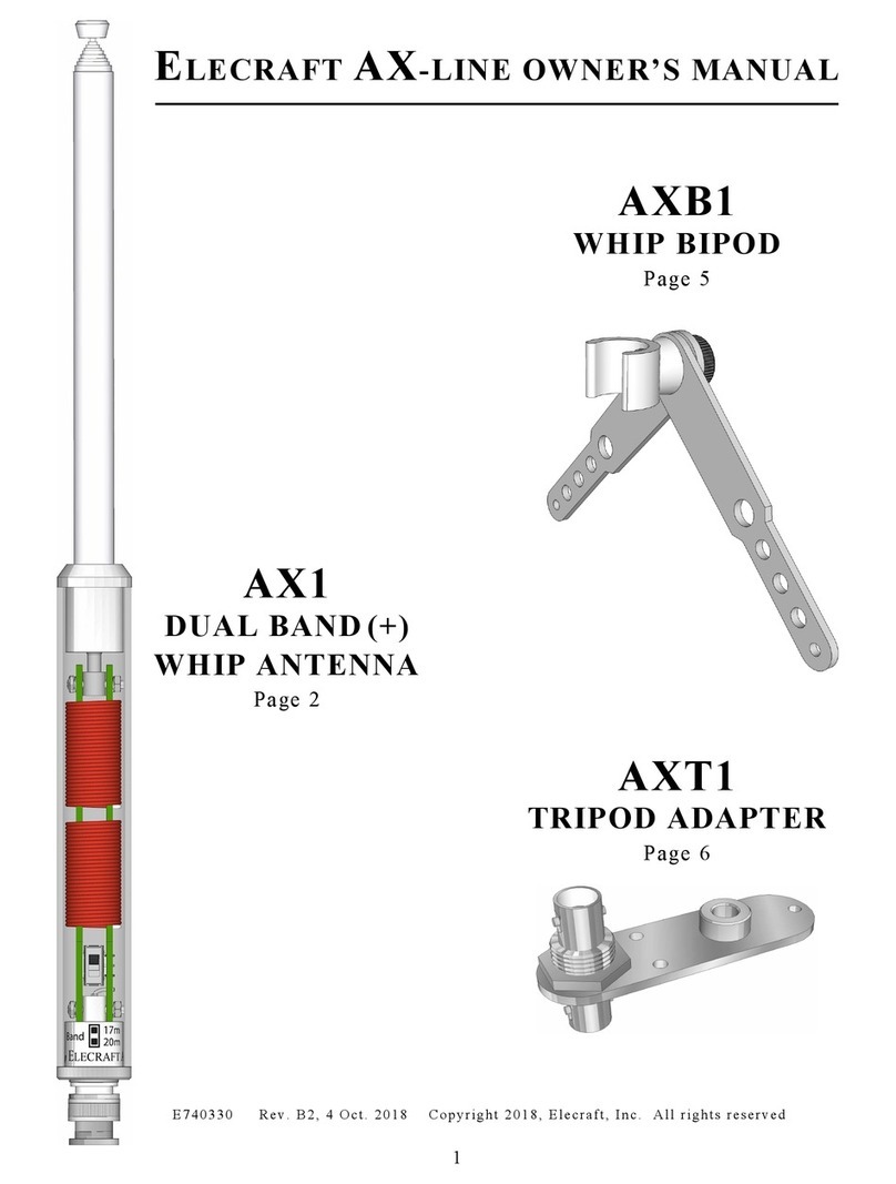
AX1
DUAL BAND (+)
WHIP ANTENNA
Page 2
AXE1
40 METER
EXTENDER
Page 7
AXB1
WHIP BIPOD
Page 5
AXT1
TRIPOD ADAPTER
Page 6
E740330 Rev. C 2 , 21 Aug. 2019 Copyright 2019, Elecraft, Inc. All rights reserved

2
Introduction
The Elecraft AX1 is a compact telescoping whip that disassembles
into 6” (15 cm) pieces, so it will fit into small “grab & go” bags... or
your back pocket. On the basic unit, a two-position switch selects
20 meters (resonant) or 17/15 meters (a low-loss match can be
achieved using an antenna tuner on both bands). The AXE1
Extender (pg. 7) adds 40 and 30 meter coverage (ATU required).
The AX1 is ideal for pedestrian mobile, “stealth” operation, or
whenever dipoles, verticals, long wires, and other full-size
antennas cannot be erected. It can be used in three ways:
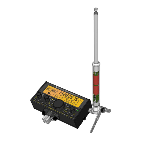
• HT-style (shown here with an Elecraft KX2 all-mode, 80-10
meter transceiver)
• On a table-top with a right-angle BNC adapter and an AXB1
whip bipod (see page 5)
• Mounted on a tripod or other support using an AXT1 tripod
adapter (see page 6)
FOR BEST RESULTS, USE THE AX1 WITH AN ATU
(automatic antenna tuner). The ATU will handle variations
in terrain, radial length, height, body capacitance, etc.
All Elecraft transceivers have optional wide-range internal
ATUs that are fully compatible with the AX1. An external
ATU such an Elecraft T1 may also be used.
Caution
• The AX1 is not intended for vehicle-mounted use or for
permanent outdoor installations.
• To avoid damage to the telescoping whip, keep it
collapsed when not in use.
• Always use at least one radial (included). This improves
transmit signal radiation by up to 20 dB, and reduces the risk of
getting an RF burn from the mic, key, or chassis at higher
power levels.
NOTE: All BNC plugs have some “play.” It’s normal for the whip to
tilt slightly when attached directly to a transceiver.

3
AX1 Setup
• If you’re using the AXE1 40 meter extender, follow the setup
instructions on pg. 7.
• Thread the whip into the base, then fully extend it.
• Plug the AX1 into your transceiver’s BNC jack for HT-style
operation. For right-angle use with an AXB1, see page 5. For
use with a camera tripod and an AXT1, see page 6.
• Select the 20 or 17 m switch position on the AX1 as shown
at left. Use the 17 m position for 15 m. (An ATU is always
required for 17 and 15 m use.)
• ATTACH AT LEAST ONE COUNTERPOISE WIRE (or radial)
to your transceiver’s ground screw. Otherwise, your transmit
signal will be as much as 20 dB weaker (4 to 5 S-units). An
insulated counterpoise wire with a spade lug at one end is
supplied with the AX1. When using a KX2 or KX3, secure the
spade lug to the rig at the thumb screw closest to the antenna
jack. (An option for the KX2 is to use a mini-banana plug, e.g.
Elecraft KX2GNDPLUG, with the quick-release ground jack on
the left side panel.)
• Match the antenna to the transceiver using an ATU or with
manual length adjustments as described below.
Using an ATU
The resonant frequency of any short whip can be affected by
many factors, including length, changes in terrain, and in the
location of the radio relative to the operator. An ATU can
compensate, eliminating tedious whip or radial length adjustments.
(An ATU is required when using the AXE1 extender; see pg. 7.)
To match using an ATU: Tap the ATU tuning switch on the radio
or tuner. If you’re using a K3S / K3 / KX2 / KX3, tapping the tune
switch a second time may result in a better match.
Manual
Adjustment
Non-ATU operation is possible on 20 meters where the AX1 is
near resonance.
To adjust antenna length manually: Check the SWR at both the
low and high end of the desired band. If SWR is higher at the low
end of the band, lengthen the radial. If SWR is higher at the high
end of the band, shorten the radial or reduce the length of the
telescoping whip.
NOTE: In cases where it is difficult to achieve a low SWR (< 3:1),
transmitting may still be possible at reduced power. Elecraft
transceivers can be safely used at high SWR.

4
Operating
Tips
• At QRP power levels, CW and certain data modes (including
FT8) will have an advantage over SSB.
• To improve signal strength, elevate the AX1 above ground by
standing or using a tripod. When operating outdoors, seek high
ground, or an area with a downslope in a preferred direction.
Such a slope may act as a reflector. Indoors, extend the
telescoping whip outside a window if at all possible, and allow
the counterpoise wire to hang outside the window as well. Use
a balcony if available.
• When operating pedestrian mobile (/PM), let the counterpoise
wire trail out behind you. As terrain changes, SWR may
fluctuate during transmit. An ATU, if available, can
compensate; tap the ATU tune button if SWR is high.
• Try operating during contests when there’s lots of activity (most
weekends). Contest stations often have high-gain antennas,
benefitting both ends of a QSO.
• Rather than call CQ, try answering strong stations who are
calling CQ or just completing a contact. A strong signal is often
an indication that propagation is excellent in that direction.
• Tune slowly, especially when listening for weak signals. As an
example, SOTA (Summits On The Air) CW stations can often
be found between 14058 and 14063 kHz, and SSB on 14340
kHz, but they may be very weak.
QRP operation with a short whip can be both rewarding
and challenging.
For times when conditions are poor, we recommend also
carrying a lightweight wire antenna. A simple random-length
antenna can be made from two 25’ (7.5 m) lengths of #26
“Silky” (thewireman.com). Counterpoise wires supplied with
the AX1 and AXE1 can also be used. Throw one wire into a
tree and lay the other on the ground, or into a second tree.
Attach the wires to the transceiver via a BNC-to-binding post
adapter, such as our model BNC-BP. Elecraft ATUs will
usually match this efficient antenna on 40 through 10 m.

5
AXB1
Whip Bipod
NOTE: The legs of
the AXB1 may not be
in electrical contact
with the whip’s BNC
connector, so they
should not be used
as a radial wire
attachment point.
A whip antenna used with a right-angle BNC may tip over due to
wind load. To stabilize a whip in light to moderate winds, an
AXB1 bipod can be used as described below.
To use the AXB1:
• Attach a right-angle BNC adapter (Elecraft
BNC-RA or equivalent) to the antenna.
• Snap the AXB1’s plastic clip firmly onto the
knurled part of the AX1’s BNC connector as
shown by the upper arrow at left.
Caution: To detach the plastic clip from the
antenna, do not snap it back off, as this can stress
the connector. Instead, slide the connector back
through the clip by pushing firmly on the BNC
adapter where indicated by the lower arrow.
• Adjust AXB1 leg angle and height as needed.
• In strong winds, orient the rig so the antenna is
facing into the wind, or strap the AXB1 to the
surface. Holes are provided in the legs.
• Firmly tighten the AXB1’s thumb screw.
• For storage or transport, fold the legs of the
AXB1 together. An AX1, AXB1 and KX2 will all
fit in an Elecraft CS40 or ES40 bag.

6
AXT1
Tripod
Adapter
Elevating a whip antenna using a tripod may improve
effectiveness on both transmit and receive. An AXT1 adapter will
work with most camera tripods having a 1/4-20 threaded mount.
Any lightweight whip with a BNC connector may be used.
To use the AXT1:
• Secure the AXT1 to the tripod’s threaded mount as shown
below.
• Attach the AX1 (or other BNC-base whip) to one of the
adapter’s BNC connectors.
• Attach a length of 50-ohm coax to the adapter’s other BNC
connector. Use the shortest possible coax cable to minimize
loss. An ATU or manual antenna length adjustments may be
required (see pg. 3).
• Attach at least one counterpoise wire to directly to the AXT1’s
aluminum bracket. A 4-40 threaded hole is provided for use
with a thumb screw or other hardware purpose. The wire may
also be connected directly to the transceiver, though this may
have a greater effect on resonant frequency. (Transmit
efficiency may be improved by using 2 or more counterpoise
wires. See pg. 8.)
• The two unthreaded holes can also be used for guying or for
attachment to a fence post or other support.
(Tripod not included.)

7
AXE1
40 Meter
Extender
The AXE1 extender allows the AX1 to be used on 40 and 30 meters. It
adds 6 inches (15 cm) of overall length. AN ANTENNA TUNER IS
REQUIRED ON 40 AND 40 METERS BECAUSE THE AX1 WHIP +
AXE1 EXTENDER IS VERY NARROW BANDED. See setup and
matching instructions below.
To set up the AXE1:
• Attach the supplied 33 ft (10 m) radial wire to the transceiver at a
point near the antenna jack. The Elecraft KX2 and KX3 provide thumb
screws for this purpose. (The AX1’s 20/17/15 meter radial and the
AXE1 radial may both be connected to the rig at the same time.)
If you do not use the radial, your transmit signal will be 20 to 30
dB weaker, and you may experience RFI problems.
• Elevate the AXE1’s radial a few feet if possible by stringing it across
foliage, rocks, picnic tables, etc. This will improve your transmit signal.
• Thread the AXE1 extender onto the AX1 base in place of the whip as
shown at left. Then thread the whip onto the extender. Do not
overtighten; this may make disassembly more difficult.
• For 40 m: Use the 20 m switch position of the AX1’s slide switch.
• For 30 m: Use the 17 m switch position. (Resonance will still be
below the 30 m band, but less ATU reactance will be required.)
• All short whips are very narrow banded. Their resonant
frequency is affected by terrain, antenna height and orientation,
and body capacitance. On 40 and 30 m, an ATU will be required to
obtain a low-SWR match (3:1 or lower recommended). If you’re using
the ATU in a KX2 or KX3, note that tapping ATU TUNE a second time
within 5 seconds may find a better match.
• For receive-only use, antenna matching is optional.
Tip #1: For transport, wind the radial wire in a figure-8 pattern (on your
fingers) to eliminate kinks and allow the radial to be deployed quickly.
Tip #2: Operation with a short antenna on 40 or 30 meters can be
challenging. Start by calling strong stations (S7+ CW, S9+ SSB). In very
poor conditions, consider using the AXE1’s radial wire itself as the
antenna, using a tree or other support. Use a second wire as a
counterpoise. Attach these wires to the transceiver using a binding post
adapter (Elecraft #BNC-BP).

8
Counterpoise
Wires
The counterpoise (or radial) wire supplied with the basic AX1 is
usable on all three covered bands (20, 17, and 15 meters). The
two inductors in the base unit have been adjusted to provide
resonance close to the 20 meter band with this radial length. The
AXE1’s longer counterpoise wire is usable on 40 and 30 meters.
Adding more radials may yield improved results on one or more
bands.
During pedestrian-mobile operation, a single “dragged
counterpoise” wire is typically used to minimize the risk of
snagging or other hazards. Optimal length for a dragged
counterpoise varies with many factors, but the length most often
used is: L (ft) = 185 / F, or L (m) = 56 / F (F in MHz).
A good starting point for elevated radials (e.g., using the AX1 with
a tall tripod or mast) is a full quarter wavelength: L (ft) = 234 / F,
or L (m) = 71.3 / F. This length also works best on 40 m (AXE1).
Radial length adjustments to achieve resonance can be tedious.
An antenna analyzer is recommended.
AX1
Specifications
Resonant
Frequencies
(by switch
position)
Supplied
Radial Wire
Max. Power
Construction
Dimensions
(approx.)
Weight
AX1: ~14 MHz (20 m), ~19 MHz (17 m).
AXE1: ~7.2 MHz (20 m), ~8.5 MHz (17 m).
Resonant frequencies may vary +/- 400 kHz
or more due to variations in terrain, antenna
height, body capacitance, and length of
radial(s).
AX1: 13 feet (4 m). AXE1: 33’ (10 m).
Includes spade lug.
30 Watts. For safety, use 15 W max when
operating hand-held. If RFI symptoms are
observed, reduce power or move antenna
farther from the transceiver.
Corrosion-resistant whip and hardware;
Lexan outer tube; high-Q inductors using
#20 AWG high-temp enamel wire.
Whip: 6” (15 cm) collapsed, 45” (115 cm)
extended. Base and AXE1 extender: 6” (15
cm) x 0.75” (19 mm) dia.
AX1: 3.2 oz. (90 g). AXE1: 2.0 oz. (55 g).

9
Customer Service and Support
Technical Assistance
You can send e-mail to support@elecraft.com and we will respond quickly – typically the same day
Monday through Friday. If you need replacement parts, send an e-mail to parts@elecraft.com.
Telephone assistance is available from 9 A.M. to 5 P.M. Pacific time (weekdays only) at 831-763-4211.
Please use e-mail rather than calling when possible since this gives us a written record of the details of
your problem and allows us to handle a larger number of requests each day.
Repair / Alignment Service
If necessary, you may return your Elecraft product to us for repair or alignment. (Note: We offer email
and phone support, so please try that route first as we can usually help you find the problem quickly.)
IMPORTANT: You must contact Elecraft before mailing your product to obtain authorization for the
return, what address to ship it to and current information on repair fees and turnaround times.
(Frequently we can determine the cause of your problem and save you the trouble of shipping it back to
us.) Our repair location is different from our factory location. We will give you the address to ship your
kit to at the time of repair authorization. Packages shipped without authorization will incur an additional
shipping charge for reshipment to our repair depot.
Elecraft 1-Year Limited Warranty
This warranty is effective as of the date of first consumer purchase (or if shipped from the factory,
the date the product is shipped to the customer). It covers both our kits and fully assembled products.
For kits, before requesting warranty service, you should fully complete the assembly, carefully
following all instructions in the manual.
Who is covered: This warranty covers the original owner of the Elecraft product as disclosed to
Elecraft at the time of order. Elecraft products transferred by the purchaser to a third party, either by
sale, gift, or other method, who is not disclosed to Elecraft at the time of original order, are not
covered by this warranty. If the Elecraft product is being bought indirectly for a third party, the third
party’s name and address must be provided at time of order to ensure warranty coverage.
What is covered: During the first year after date of purchase, Elecraft will replace defective or
missing parts free of charge (post-paid). We will also correct any malfunction to kits or assembled
units caused by defective parts and materials. Purchaser pays inbound shipping to us for warranty
repair; we pay shipping to return the repaired equipment to you by UPS ground service or equivalent
to the continental USA and Canada. For Alaska, Hawaii, and other destinations outside the U.S.
and Canada, actual return shipping cost is paid by the owner.
What is not covered: This warranty does not cover correction of kit assembly errors. It also does
not cover misalignment; repair of damage caused by misuse, negligence, or builder modifications;
or any performance malfunctions involving non-Elecraft accessory equipment. The use of acid-core
solder, water-soluble flux solder, or any corrosive or conductive flux or solvent will void this warranty
in its entirety. Also not covered is reimbursement for loss of use, inconvenience, customer assembly
or alignment time, or cost of unauthorized service.
Limitation of incidental or consequential damages: This warranty does not extend to non-
Elecraft equipment or components used in conjunction with our products. Any such repair or
replacement is the customer. Elecraft will not be liable for any special indirect, incidental or
consequential damages, including but not limited to any loss of business or profits.
This manual suits for next models
4
Table of contents
Other ELECRAFT Antenna manuals
Popular Antenna manuals by other brands

Zehnder Rittling
Zehnder Rittling AX 40 instructions

Directive Systems & Engineering
Directive Systems & Engineering DSE9112LY manual

Directive Systems & Engineering
Directive Systems & Engineering DSE1445LY quick start guide

Chameleon Antenna
Chameleon Antenna EMCOMM III Operator's manual

CommScope
CommScope ARGUS U Series Installation and operation instructions

Ultra Beam
Ultra Beam UB640-VL2.3 manual