manuals.online logo
Brands
  1. Home
  2. •
  3. Brands
  4. •
  5. Ultra Beam
  6. •
  7. Antenna
  8. •
  9. Ultra Beam UB640-VL2.3 User manual

Ultra Beam UB640-VL2.3 User manual

1
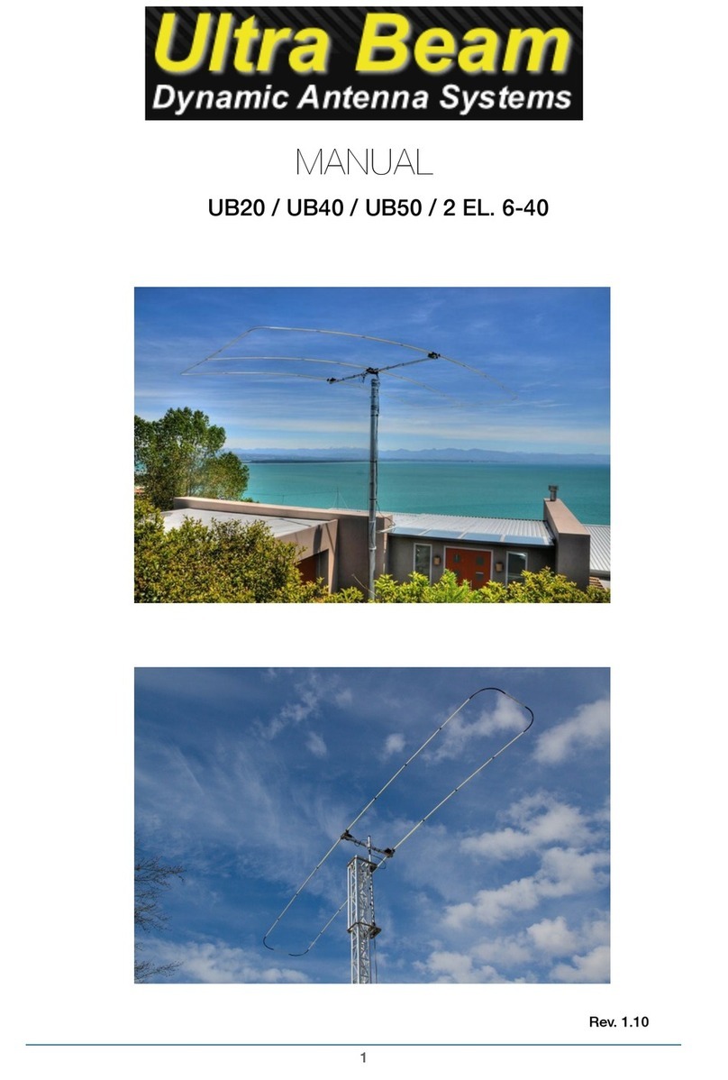
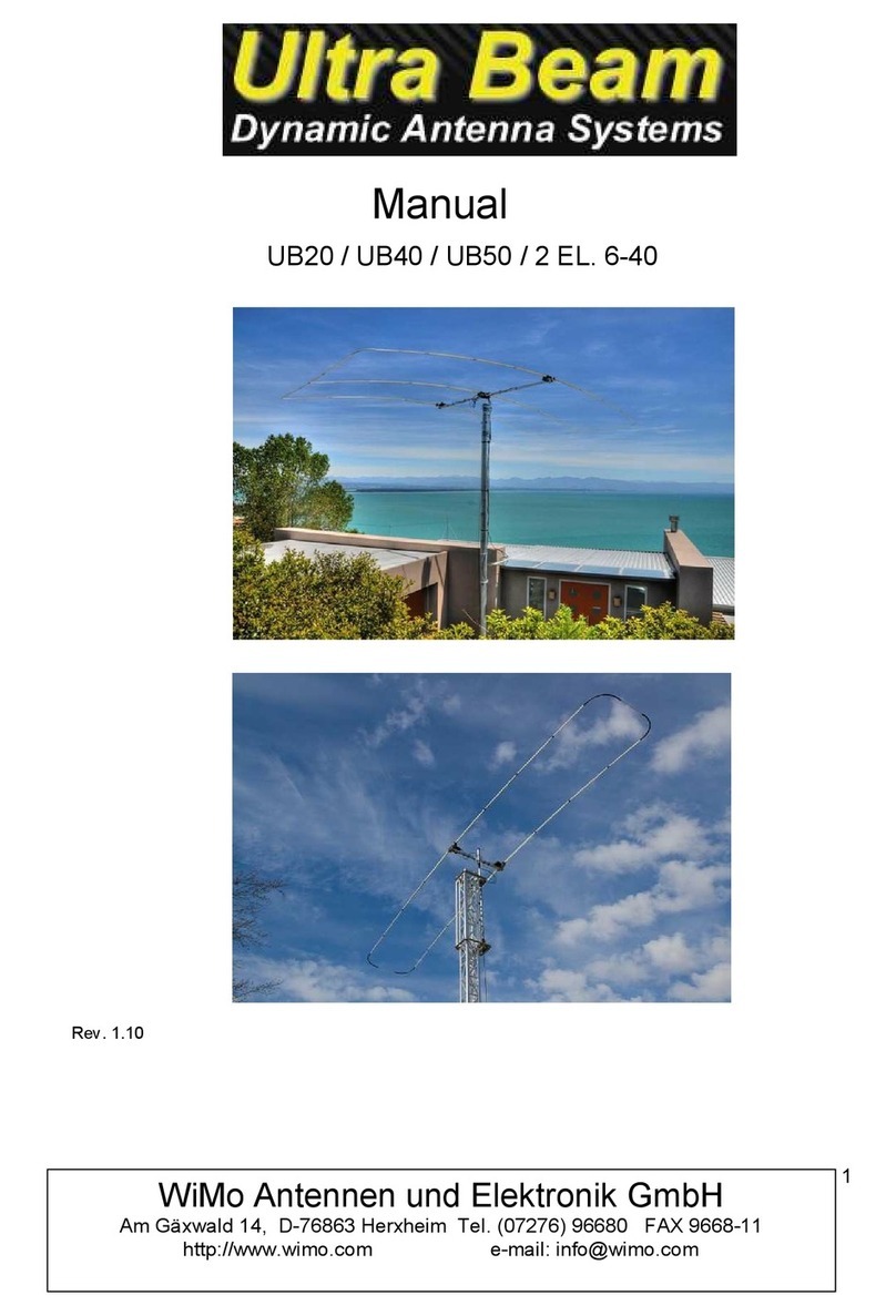
“LOOP ELEMENT” MANUAL
UB640-VL1.1 / UB640-VL1.3 / UB640-VL2.3 / UB640-VL3.4
Rev. 1.10
2
VERTICAL LOOP ELEMENTS ASSEMBLY
Th s manual refers exclus vely to the element assembly procedures of vert cal loop employed n
models UB640-VL1.3 - UB640-VL2.3 - UB640-VL3.4.
All other nstruct ons for the mount ng of the antenna s conta ned n the manual "Standard".
The VL2.3 and VL3.4 models have dual dr ver, you w ll need to download the "Sw tch" manual for
nstruct ons about connect ng the electron c sw tch and coax al cables.
Vert cal loop d agram
The manual conta ns the nstruct ons for the complete assembly of a folded loop element.
The procedures are the same for all loops regardless of be ng dr ver-operated or be ng just a
pass ve element.
It w ll be suff c ent to perform the nstallat on on the boom n the pos t on nd cated by the "antenna
pattern" of your model.
ABS collar up
gu de pvc tube
f berglass rod
ABS collar down
3
1) SUPPORT ASSEMBLY OF LOWER LOOP ELEMENTS
The lower element of the loop s supported by an alum n um square sect on 60x60mm
placed d rectly below the motor un t.
It s f xed to the boom by means of two alum n um plates "A" (f g.1)
Assemble the plates to the s des of the boom w th 6 M6-bolts
Insert the "B” square sect on to form a T, t ghten the tube so that t rema ns n place.
Check w th a set square to obta n a 90 ° angle (F gure 2) and t ghten all bolts.
The plates w ll behave l ke a clamp and w ll ma nta n stab l ty of the ent re lower support.
F g.1
F g.3 F g.2
The lower elements of the loop are nstalled on a plate s m lar to the motor supports (f g.3)
Install the alum n um support at the lower end of sect on "B" (f g.2). Check angle 90 °
before t ghten ng the bolts.
Install the res n glass tube "C" w th exactly the same procedure as used at the motor
un ts (See "Standard" manual).
C Support w ll keep the lower elements perfectly parallel to the upper ones, f xed to the motor
un t.
90°
B
A
C
4
2) INSTALLATION OF MOTOR UNITS AND SUPPORT GUYS
Install the motor un t on the support by follow ng nstruct ons manual "Standard".
F x the alum n um U holder (f g.4) above the ABS collars by means of the two bolts M6 x
120mm ncluded n the screws k t.
Install the vert cal st ck on the U support (F gure 5) and secure t us ng the two M6
bolts. F g. A shows the sect onal v ew of the correct al gnment of the parts nclud ng the
rope.
F g.
4
F g.
5
TIGHTENING BOLTS
Thread Description Clamping Nm
M6 Plates A (f g.1) 17 Nm
M6 Plates elements support lower
(f g.2)
10 Nm
M6 ABS collars lower tube (f g.3) 8 Nm
M6 Support “U” bolts (f g.4) 8 Nm
M6 St ck rope bolts (f g.5) 8 Nm
5
motor
un t
A
3) PREPARATION AND GUIDE TUBES
All motor un ts of the vert cal loop elements requ re the nstallat on of nternal gu de tubes n
the upper elements connected to the motor un t "A"
The gu de tube on folded elements s essent al so that the tape can sl de w th n the
curve and along the lower element
The gu de element s composed of two sect ons of PVC p pe 2 x 1500mm total length 3 meters.
Jo n the two PVC sect ons and tape w th common nsulat ng tape.
Insert another junct on at one end, th s w ll be helpful to connect the gu de tube to the motor
un t (F g.1-2).
Insert the gu de tube nto the prev ously assembled element (F gure 3)
F g.1 F g.2 F g.3
Internal PVC guide tube junct on junct on
tape
tape
tape
6
4) ELEMENTS INSTALLATION ON MOTOR UNIT
Before nsert ng the elements nto the motor un t, t s necessary to f x the PVC gu de
tube. Dur ng th s operat on t s necessary that the elements rema n al gned to the motor,
f your mount ng set-up does not allow th s, t s absolutely requ red to ga n ass stance by
a second person to hold the support element dur ng the nsert on of the gu de tube.
Ins de the PVC p pe, wh ch s go ng nto the eng ne, a double-s ded adhes ve has been appl ed that w ll
keep the junct on steady and avo d ts detachment (F gure 4)
Place the PVC p pe unt l t reaches ts max mum nsert on (F gure 1)
Place the telescop c element n the motor un t unt l t stops and t ghten the clamp of rubber sleeve.
F g.1 F g.2 F g.3
Important note:
You need to carefully and correctly nstall the gu de tubes.
In case of poss ble detachment of even a s ngle tube, the copper tape w ll bend nev tably
damag ng the motor dr ve funct onal ty.
F g.4
7
5) LOWER ELEMENTS ASSEMBLY
Install the lower elements on the lower support just l ke on a motor un t.
In F g.1 the scheme of the pos t on and placement of the elements nto f berglass tube
mounted on the support s d splayed.
Insert the element 10 cm and lock t w th the outer bands of rubber sleeves.
6) SUPPORT ROPES INSTALLATION
The str ngs are attached to the elements by means of two spec al ABS collars (f g.2) placed n the central
junct on of the telescop c element, to th s junct on the thermos-shr nk ng tub ng does not apply.
Place two o r ng elemens as shown n f g.3-4
Close the two ABS shells by means of M4 screws (F gure 5). Eeven closed, the ABS holder w ll rotate on
tself, th s s normal, the nternal notch placed between the two o r ngs w ll prevent t from sl pp ng nward.
F g.2 F g.3 F g.4 F g.5
support C
F g.
A
B
8
The two collars A and B are jo ned by a f berglass rod (f g.6) that mechan cally b nds the upper to the lower
element, th s s necessary to ma nta n the un form geometry of the loop and at the same t me t d str butes the
str ng support to the lower element.
The f berglass rod s f xed to the supports by means of one of the 4 lock ng bolts (page 9 - f g. C)
NOTE: As ment oned n the "Standard" manual, there may ex st small d fferences n length between the
elements and then between the junct ons, for th s reason t can happen that the bottom jo nt B s not perfectly
al gned w th the upper, even f th s s not of great mportance, you can correct the al gnment of the lower
coupl ng by adjust ng the nsert on of the lower element nto the “C” support (page 7-f g.1). The space of 10
cm ns de the tube hold ng of the elements s suff c ent to compensate for any m sal gnment of the lower
support
B.
F g.6
7) INSTALLATION LOOP CURVES
The outer loops are f xed, w th h gh mechan cal res stance, by the nternal
adhes ve heat shr nk sleeve.
Insert the sheath nto the element and then nsert the same nto the
PVC 180 °curve (normally enter 8-10 cm).
Sl de the sheath over the jo nts, and heat w th the heat gun
The procedure s the same one used for the telescop c elements.
Note: the surfaces must be cleaned before appl cat on
Before heat ng the sheaths check
the al gnment of the loop n order to avo d a candy
shape (aesthet cs factor).
After the appl cat on t s necessary to wa t unt l the
sheath s completely cold.
Tw st ng or movements of the jo nt when st ll warm
and not completely cold can mpa r the mechan cal
seal and the waterproof of the jo nt.
A
B
9
8) ROPE MOUNTS
F g.7
F g.8
A MastrAnt P k t of ropes of su table length s prov ded for the construct on of the t e rods.
T e the rope to the r ght and left C supports through the double junct on eyelet (F gure 7)
Then s mply attach the rope (one sect on) to the alum n um st ck placed on the motor un t (f g.8). Cut
of the excess rope from one of the two C supports only when the correct length has been obta ned.
The elements must not look up, the correct tens on of the str ngs s g ven by the al gnment of the C
supports (f g.9) wh ch must not be h gher than the motor dr ve tube
A possible downward trend is recommended, deal to al gn the loops w th the same ncl nat on of
normal elements (no loops) of your antenna (F gure 10)
Three holes n the st ck w ll allow you a small f nal correct on to the tens on of the str ngs w thout
remov ng the rope from the junct on.
F g.10
C
F g.9 C
C
Natural ncl nat on telescop c
element Ideal ncl nat on loop
element
10
VL-SERIES ANTENNA DIAGRAM
r 2
1
Dr v
e
Dr ver
11
244 cm 235 cm
DIAGRAMMA
ANTENNA
180° Normal 180° Normal
UB640 - VL1.3 UB640 - VL2.3
12
ELEMENTS LENGTH / GUIDE PVC TUBES
odello No loop External loop / PVC tube Central loop / PVC tube
UB640-VL1.1 / / 5,4 m. / 3 m.
UB640-VL1.3 5,4 m. / 5,4
UB640-VL2.3 5,4 m. 5,4 m. / 3 m. /
UB640-VL3.4 5,4 m. 5.4 m. / 3 m. 7,4 m. / 4,5 m
UB640 - VL3.4
180°
Normal
reflecti
Dr ver 1
Dr ver 2
D rectr
Reflector 10-40

conductor
10-40
Dr ver 10-20

Dr ver 10-20
 Reflector 10-20 / Dr ver
30
-
40
D rector 10-20 / Dr ver 30-40
D rector 10-40

Reflector
12
The VL1.1 d pole s prov ded w th a spec f c alum n um square mast wh ch s mpl f es the assembly of the
d pole on your mast and prov des better support for all parts compared to an nstallat on on round Mast. The
VL1.1 s the only antenna where the ma n hardware parts are pre- nstalled by UltraBeam, you only have to
complete the nstallat on of the elements and the t e rods.
The nstallat on procedures of the elements are dent cal to those nd cated for the VL-Ser es so refer to these
manuals pages: 2-5-6-7-8-9 and "Standard Manual" (page 5) for elements assembl ng
NOTE:
All bolts of the parts pre-installed by UltraBeam have been already tightened correctly, do
not further tighten!!
As for all models it is recommended to correctly read the installation instructions.
UltraBeam will not be liable for malfunctions or damage caused by your setup!!
UP
bolt for truss
U
-
Bolts mast
13
Th s p cture shows UB640-VL1.1 nstalled n mast by the customer.
Th s p ctures show the UB640-VL1.1 antenna wh ch s assembled n the sh pp ng box
W Mo Antennen und Elektron k GmbH
Am Gäxwald 14, D-76863 Herxhe m Tel. (07276) 96680 FAX 9668-11
http://www.w mo.com e-ma l: nfo@w mo.com

This manual suits for next models

3

Other Ultra Beam Antenna manuals

Ultra Beam UB20-MX User manual

Ultra Beam

Ultra Beam UB20-MX User manual

Ultra Beam UB20 User manual

Ultra Beam

Ultra Beam UB20 User manual

Popular Antenna manuals by other brands

KVH Industries TracVision UHD7 installation guide

KVH Industries

KVH Industries TracVision UHD7 installation guide

Motorline professional MA115 installer and user manual

Motorline professional

Motorline professional MA115 installer and user manual

Ubiquiti airMAX Omni AMO-5G13 quick start guide

Ubiquiti

Ubiquiti airMAX Omni AMO-5G13 quick start guide

Enterasys RoamAbout Site preparation and installation guide

Enterasys

Enterasys RoamAbout Site preparation and installation guide

Ubiquiti RocketDish RD-5G30 quick start guide

Ubiquiti

Ubiquiti RocketDish RD-5G30 quick start guide

RCA ANTB55E quick start guide

RCA

RCA ANTB55E quick start guide

CPI 1194 Series Assembly manual

CPI

CPI 1194 Series Assembly manual

Directive Systems & Engineering DSEFO144-12 manual

Directive Systems & Engineering

Directive Systems & Engineering DSEFO144-12 manual

Megasat Campingman Portable User manual and installation instructions

Megasat

Megasat Campingman Portable User manual and installation instructions

Fracarro TAU11 quick start guide

Fracarro

Fracarro TAU11 quick start guide

KING One Pro KOP4800 owner's manual

KING

KING One Pro KOP4800 owner's manual

Mohu Sail instructions

Mohu

Mohu Sail instructions

TRENDnet TEW-AI75O Specifications

TRENDnet

TRENDnet TEW-AI75O Specifications

Wilson Electronics 301134 installation guide

Wilson Electronics

Wilson Electronics 301134 installation guide

Radio Shack VU-190XR owner's manual

Radio Shack

Radio Shack VU-190XR owner's manual

Patriot Antenna 1.8m Offset TxRx Installation & assembly instructions

Patriot Antenna

Patriot Antenna 1.8m Offset TxRx Installation & assembly instructions

Q-Mac TA-90 Technical manual

Q-Mac

Q-Mac TA-90 Technical manual

Hirschmann Hit FESAT 65 operating instructions

Hirschmann

Hirschmann Hit FESAT 65 operating instructions

manuals.online logo
manuals.online logoBrands
  • About & Mission
  • Contact us
  • Privacy Policy
  • Terms and Conditions

Copyright 2025 Manuals.Online. All Rights Reserved.