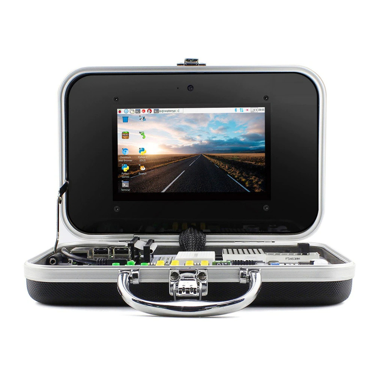
Elecrow Crowtail Deluxe Kit User manual

www.elecrow.com
2020 ELECROW All Rights Reserved.
C
User Guide
V2.0 2020.02
Crowtail Deluxe Kit
for Arduino

ContentContent
2020 ELECROW All Rights Reserved.
C
Instruction
Modules List
Crowtail
● Crowtail - Motor Base Shield
● Crowtail - Module
Lessons
● Lesson 1 - LED control
● Lesson 2 - Collision experiment
● Lesson 3 - Hall speed test
● Lesson 4 - Motor control
● Lesson 5 - Tracing experiment
● Lesson 6 - Over temperature reminder
● Lesson 7 - Colorful RGB light
● Lesson 8 - Show text on OLED
● Lesson 9 - Ultrasonic ranging display
● Lesson 10 - Use of the joystick
● Lesson 11 - Servo control
● Lesson 12 - Smart door
● Lesson 13 - IR control
● Lesson 14 - Store data
● Lesson 15 - Calculation of acceleration
● Lesson 16 - Use of gyroscope
● Lesson 17 - Use of Bluetooth
● Lesson 18 - ESP8266 web server
● Lesson 19 - A naughty robot
● Lesson 20 - A remote control car
01
02
03
03
04
05
05
07
08
10
13
15
17
19
20
22
24
26
28
30
32
34
35
37
40
42

InstructionInstruction
Welcome to the user manual of the Crowtail-Deluxe kit for Arduino. The electronic world is
so exciting and amazing! Probably you can't wait to create more interesting works or even
realize your electronic dream. Just wait a minutes, let’s get to know this amazing kit first.
The Crowtail-Deluxe Kit for Arduino is a kit for advanced learners with a basic programming
foundation. It is designed to help learners diverge their ideas, learn how more complex
electronic components work and program, and ultimately help them achieve their dream
electronic project! The kit contains more than 20 creative and inspiring courses, from simple
to difficult, to guide you in detail to learn how these complex electronic modules work and
how to use them, and then program to achieve challenging and creative electronic projects
that will even teach you how to create your own artificial intelligence work! In all, by learning
this kit, you will learn how to build a smart car completely, including wireless remote control,
intelligent tracking or obstacle avoidance, etc. Of course, there are more complex move-
ment data acquisition, wifi and Bluetooth use!
The Crowtail-Deluxe kit for Arduino includes more than 20 electronic modules, which are
selected one by one from more than 100 Crowtail electronic modules. The kit is designed to
let you learn some complex electronic modules and learn how they work and how to use
them. In addition, the kit will broaden your thinking, help you inspire more novel ideas and
creations, and ultimately help you achieve your dream work!
For the programming part, we will use Arduino software for programming. As you know,
Arduino is an easy-to-use open source electronic prototyping platform. It is one of the most
popular open source hardware in the world, including hardware (various Arduino board
models) and software (Arduino IDE). This is the easiest and best choice for you to learn
programming and hardware and achieve creative work. In short, you will explore the core of
electronic device programming and creation, and help you create your own great work with
a more comprehensive mind.
01

02
Modules ListModules List
● Crowtail - Motor Base shield x1
● Crowtail - Buzzer x1
● Crowtail - Switch x1
● Crowtail - LED(Red) x1
● Crowtail - Bright LED x1
● Crowtail - RGB-LED x1
● Crowtail - OLED x1
● Crowtail - IR Reflective Sensor x3
● Crowtail - Thumb Joystick x1
● Crowtail - IR Receiver x1
● Crowtail - IR Emitter x1
● Crowtail - Hall Sensor x1
● Crowtail - One Wire Waterproof Temperature Sensor x1
● Crowtail - Collision Sensor x1
● Crowtail- Ultrasonic Ranging Sensor x1
● Crowtail- 3-Axis Digital Accelerometer(±16g) x1
● Crowtail - 9G Servo x1
● Crowtail - ESP8266 nodeMCU x1
● Crowtail - Analog Gyro x1
● Crowtail - I2C EEPROM x1
● Crowtail - Bluetooth Low Energy Module x1
● Micro-Speed Motor x2
● Small magnet x1

03
Crowtail
Crowtail – Base Shield
Welcome to the world of Crowtail! Crowtail is a modulated, ready-to-use toolset, it takes a building
block approach to assemble electronics. It simplifies and condenses the learning process significantly.
In our Crowtail warehouse, there are over 150 Crowtail modules and Crowtail shields!
The Crowtail products are basic-functional modules that consist of a Base Shield and various modules
with standardized connectors, each Crowtail module has its specific functions, such as light sensing
and temperature sensing. It will satisfy all you need for your project!
Crowtail is a series of products that we made to solve the messy jumper when connecting electronic
circuits. It consists of a Base Shield and some basic Crowtail modules, which help you create small,
simple, and easy-to-assemble circuits. In other words, when you use Crowtail, your electronic project
will not be messy wiring, instead, it will be a simple and easy to manage an electronic project!
For those who want to use Arduino to build their own DIY mobile platform, motor drive has always
been a problem. It need 2 DC motors at least to control their speed& direction of rotation because
you will want your platform forward, turn back, turn left or right. Besides, motors always need large
current, so, you will need some modules to help you control the large current, with a microcontroller
such as Arduino. Then, the Crowtail-Motor Base shield appears, it can meet your all demand to DIY
your mobile platform! The Crowtail-Motor Base Shield is a standard IO expansion motor driver board
for the Arduino. It regulate the IOs of Arduino to the standard Crowtail interface and have two
interfaces to drive motors or a interface to drive 4-wire stepper, which can be sorted into 4 kinds:
Analog(A), Digital(D), UART(D0&D1, D2&D3) and IIC(A4&A5):
6 Digital I/O ports (D2~D7) that have a mark “D”. These ports can be used to read and control
digital Crowtail modules (Crowtail modules that have a mark “D”), such as the Button and LEDs.
Some of the digital I/O ports can also be used as PWM (pulse width modulation) outputs;
3 Analog ports (A0~A2) that have a mark of “A”. Besides the functional of digital, these A
ports can read the analog signal, such as a potentiometer or light sensor;
1
2
3
4
2
1

04
Crowtail – Modules
We make more than 100 kinds of electronic modules into Crowtail modules. They include a variety of
sensors, displays, inputs and outputs modules, communication types include I2C, UART, digital or
analog, which aim to provide more options to fully meet all needs for your electronic projects! All
modules can be used by simply connecting them to the Crowtail-Motor Base shield using a Crowtail
cable, which is a huge improvement over the previously troublesome jumper connections.
2 UART ports(D0&D1, D2&D3) that have a mark of “U”. These interfaces can be used for UART
communication such as the WIFI module or Bluetooth module;
1 IIC ports(A4&A5) that have a mark of “I”. These interfaces are for the IIC Communication;
Besides, there is also two motor connector, which you can drive 2 motors simultaneously or drive a
4-wire stepper. Users can connect any electronic modules to the Base Shield with Crowtail cable
easily.
Compared with the traditional way of carrying out electronic projects, Crowtail has a huge performance
benefit. All Crowtail has the standard 4 pin connectors. Your creative idea can be realize easier and
faster just by plug and play. In addition, you don’t need to debug the electronic circuits!
3
4
Connect Crowtail- Motor Base shield
with your Arduino
Connect Crowtail- Motor Base shield
with your Crowduino

05
Crowtail bright LED is a bright LED light with high brightness
and a large angle. Then its low terminal resistance can be
applied to indoor lighting, commercial lighting. Unlike colored
LEDs, Crowtail bright led light is white, very similar to our
daily light source and you can use it to make your own table
lamp. It can provide a strong light source for your project,
lighting, or so on.
The Crowtail- Switch is a Latching switch. When the switch is pressed
for the first time, the switch maintains current regulation and the button
outputs a HIGH signal in the self-locking state. When the switch is
pressed for a second time, the switch button pops up and the switch
turns off and then outputs a LOW signal. In fact, it is very similar to the
button, except that the switch has a self-locking function so that it can
output logic high level signal without pressing it all the time.
In this lesson, we are going to use bright LED module and switch to make a corridor night lights,
which will produce a strong illumination light for those who need it. Let’s start playing and see the
difference form colored LEDs.
Lesson 1 – LED Control
Lessons
Introduction
Arduino Uno/Crowduino Uno x1
Crowtail - Motor Base Shield x1
Crowtail - Bright LED x1
Crowtail - Switch x1
Crowtail - Cable x2
Required Parts
STEP1: Plug the Crowtail-Motor Base Shield onto the
Arduino or Crowduino board.
Hardware Connection
STEP2: Connect the Crowtail-Switch and Crowtail-Bright
LED to the D2 and D3 ports of the Crowtail-Motor Base
Shield. The complete connection is as follows.
Open the P01_LED_Control with Arduino IDE
and upload it.

06
When you press the switch, the bright LED will immediately light up, and the LED will go out when
you press the switch again to make the switch button pop up.
What will you see
1. Declare the LED and switch pins, and the “switchstate” variable to store the state of the button
2. Setup the LED as output and switch as input.
3. Read the state of the switch.
4. If the switch is pressed(HIGH), turn the LED on.
5. If the switch is pressed again and switch button is pop up(LOW), turn the LED off.
Code overview
Code usage
A variable is a placeholder for a value that may change in your code.
Variables must be introduced or "declared" before using variables.
Here, we declare two variables that define which ports of the base shield
the module should connect to and a variable called ‘switchState’
of type int(integer) and assign it a value of 0 to record the status of
the switch. Don't forget that variable names are case-sensitive!
Input or Output
Before using one of the digital pins, you need to tell Arduino
whether it is an input (INPUT) or an output (OUTPUT).
We use a built-in "function" called pinMode() to make the pin
corresponding to the led as an output and switch as an input.
Digital Input
We use the digitalRead() function to read the value on a digital pin.
Check to see if an input pin is reading HIGH(5V) or LOW(0V).
Returns TRUE(1) or FALSE(0) depending on the reading.
If/else Statements
The if / else statement allows your code to make corresponding choices
for different results, running a set of code when the logical statement in
parentheses is true, and another set of code when the logical statement is
false. For example, if the switch is pressed, the LED will light on and when
the switch is pressed a second time and the switch button is pop up,
the LED will light off.
This is another logical operator.The "equal" symbol (==) can be confusing.
The two equal signs are equal to ask: “The two values are equal
to each other? “On the other hand, if you want to compare two values,
don't forget to add a second equal sign, because if it's just a "=",
it's an assignment method.
Is equal to
When you're using a pin as an OUTPUT, you can command it to be
HIGH (output 5 volts) or LOW (output 0 volts). When you set it to HIGH,
for digital output modules, it means work. When you set it to LOW,
for digital output modules, it means don't work. For example, the led will
light on(work) when it is set to HIGH and it will light off(don't work)
when it is set to LOW.
Digital Output
Integer Variables

07
This is a Robot model car crash or collision switch sensor module for
Arduino, it normally outputs a logic HIGH signal, but when the sensor
crash something such as the wall, the on-board switch will be pressed,
and the module outputs a logic LOW signal. This module can be
installed into any mobile platform to achieve collision detection function
via 4 pin sensor cable and Arduino sensor expansion board connector.
Do you know why the car opens the airbag immediately after the
impact? In fact, the collision sensor is used to detect collisions in the
car, so we will simulate a car detection project in this lesson, which will
be absolutely cool if installed in your own smart car.
Lesson 2 – Collision experiment
Introduction
Arduino Uno/Crowduino Uno x1
Crowtail - Motor Base Shield x1
Crowtail - Collision Sensor x1
Crowtail - LED x1
Crowtail - Buzzer x1
Crowtail - Cable x3
Required Parts
STEP1: Plug the Crowtail-Motor Base Shield
onto the Arduino or Crowduino board.
Hardware Connection
STEP2: Connect the Crowtail-Collision
Sensor to the D3 port of the Crowtail-Motor
Base Shield. Connect the Crowtail-LED and
Crowtail-Buzzer to the D5 and D6 ports of
the Crowtail-Motor Base Shield. The
complete connection is as follows.
Open the P02_Collision_Experiment with
Arduino IDE and upload it.
When you press the onboard switch, you can see the red indicator light on the collision sensor, led
and buzzer will work for 0.5 seconds, when you release the switch, the red indicator light on the
board Off, led and buzzer no longer light up and beep.
What will you see

08
The Crowtail-Hall Sensor uses the Allegro™ A1101 Hall-effect
switches are next-generation replacements for the popular
Allegro312x and 314x lines of unipolar switches. It measures the Hall
Effect, which is a production of a voltage difference across an
electrical conductor, transverse to an electric current in the conductor
as well as a magnetic field perpendicular to the current.
Lesson 3 – Hall speed test
Introduction
1. Macro definitions of PIR motion sensor pin, LED pin and buzzer pin.
2. Declare a variable to store the state of the collision sensor.
3. Setup led and buzzer as output.
4. Read the state of the collision sensor and store it to the variable collisionState.
5. If collision is detected(LOW), turn led and buzzer on for 0.5 seconds.
6. If a collision is not detected(HIGH), turn led and buzzer off.
Code overview
Code usage
The prototype of the macro definition constant is #define [MacroName] [MacroValue]. What is the
difference between a macro definition constant and a variable? First, Macro-defined constants
cannot be changed while the program is running. Variables can be changed. Second, the variable
can be used inside the function defined by it, but the life cycle end when the function ends. The
macro defines the constant until the entire program runs the life cycle ends.
Macro definition: #define collisionPin 3 #define ledPin 5 #define buzzerPin 6
It Causes the program to wait on this line of code for the amount of time in between brackets. After
the time has passed, the program will continue to the next line of code.
Delay: delay(500); delay(200);
The if / else statement allows your code to make corresponding choices for different results, running
a set of code when the logical statement in parentheses is true, and another set of code when the
logical statement is false. For the collision sensor, when the on-board switch of the collision sensor is
pressed, the state of the collision sensor is LOW which is different from most modules and it will be
HIGH when the on-board switch of collision sensor is not pressed.
If/else Statements: if(logic statement) {code to be run if the logic statement is true}
else {code to be run if the logic statement is false }

09
The output of the continuous-time switch Hall sensor output logic low(turns on) when a magnetic
field (south polarity) perpendicular to the Hall sensor exceeds the BOP threshold, and it output logic
high( turn off) when the magnetic field disappears.
The Hall sensor is a very practical electronic module. It can be applied in many aspects, such as
measuring displacement, measuring speed and so on. In this lesson, we will do a simple speed
measurement experiment with a hall sensor, let's start turning.
STEP1: Plug the Crowtail-Motor Base Shield
onto the Arduino or Crowduino board.
Hardware Connection
STEP2: Connect the Crowtail-Hall Sensor to
the D2 port of the Crowtail-Motor Base
Shield. Connect the Crowtail-LED to the D3
port of the Crowtail-Motor Base Shield. The
complete connection is as follows.
Open the P03_Hall_Speed_Test with Arduino
IDE and upload it.
Open the serial port monitor. When you use the magnet's S polar to approach the hall sensor, the
red indicator light on the hall sensor will light up and the speed count will increase by one. When
you repeat the action within the 5 second count time, the count will follow the number of times the
S-Class approaches the Hall sensor are superimposed and printed out after five seconds.If the
count of speed more than 20, the LED will lights on, otherwise, the LED will lights off.
What will you see
1. Declare the hall sensor and led pins.
2. Define the time interval of each measurement, a variable to timing and a variable to count.
3. Initialize the serial monitor and set the baud rate.
4. Call interrupt function to count speed.
5. Start timing and get the current system time.
6. If the count of speed more than 20, print the count of speed every 5 seconds and turn led on.
7. If the count of speed less than 20, print the count of speed every 5 seconds.
Code overview
Arduino Uno/Crowduino Uno x1
Crowtail - Motor Base Shield x1
Crowtail - Hall Sensor x1
Crowtail - LED x1
Crowtail - Cable x2
Required Parts

10
The 5V, 83rpm Micro DC Geared Motor with Back Shaft is ideal for DIY enthusiasts. This motor is
inexpensive, small, easy to install, and ideally suited for use in a mobile robot car. Its no-load speed
is 50rpm under 3V voltage operation and 83rpm under 5V voltage operation.
Lesson 4 – Motor control
Introduction
Code usage
'const' is the abbreviation of constants. If you use this to define variables, the variables are marked
as “read-only”, that is, they cannot be changed during the program. Constants are great for declaring
pin number variables that will not change throughout the program. Here we declare the “taketime”
constant and it assigned to 5000, which mean we will get the count of speed every 5 seconds.
Constant: const int taketime = 5000;
The prototype of the interrupt function is: attachInterrupt(interrupt,function,mode). “Interrupt”:
Interrupt source (In Arduino, the selectable value of the interrupt source is 0 or 1, generally
corresponding to pins 2 and 3 respectively). “function”: the name of the function that needs to be
interrupted. “mode”: LOW (low level trigger), CHANGE (trigger when change), RISING (low-level to
high-level trigger), FALLING (high-level to low-level trigger). We use a Hall sensor as the interrupt
source connected to the D3 port. When the interrupt occurs (the S level of the magnet is close to the
Hall sensor), this means that the high level signal of the Hall sensor will become a low level signal,
and then we run the code in the count function.
Interrupt function: attachInterrupt(digitalPinToInterrupt(interruptPin), count, FALLING);
Each type of integer is divided into two types: unsigned and signed (float and double are always
signed). In data types other than char, integers declared by default Type variables are all signed
types; char is always unsigned by default. The long keyword represents a long integer type, which is
a basic data type in a programming language. It is an abbreviation of long int. The default is a signed
long integer type.
Unsigned long integer: unsigned long time;
This function returns the number of milliseconds when the Arduino board starts running the current
program. This number overflows after about 50 days and returns to zero. By using this function, we
can precisely control the program to calculate the count of speed every 5 seconds and print it out in
the serial monitor.
Millis() function: time = millis();

11
STEP1: Plug the Crowtail-Motor Base Shield
onto the Arduino or Crowduino board.
Hardware Connection
STEP2: Connect the two Micro-Speed Motor
to motor interface of Crowtail-Motor Base
Shield. The OUT1 and OUT2 interfaces are
connected to the same motor positive and
negative poles, and the OUT3 and OUT4
interfaces are connected to the same motor
positive and negative poles.
Our Crowtail-Motor Base Shield includes 2 motor interfaces,
which can drive two motors at the same time! Of course, a
4-wire stepper motor can also be driven. After inserting the
Crowtail-Motor Base Shield into Arduino/Crowduino, the specific
method of controlling the motor is as follows:
In this course, we will use the Crowtail-Motor Base Shield motor interface to control two TT motors
simultaneously. This includes not only controlling the on or off of the motor, but also the speed of the
motor, which means that you can implement controls such as turning. Add "legs" to your smart car!
Arduino Uno/Crowduino Uno x1
Crowtail - Motor Base Shield x1
Micro-Speed Motor x2
Jumper wire x4
Required Parts

12
Be careful not to connect the motor to the interval interface, such as OUT1 and OUT3, otherwise, the
motor will not work properly. The complete connection is as follows.
Note: Because the motor consumes more power, after uploading the code, you need to provide additional
power for the Crowtail-Motor Base Shield (usually connect 9V power supply for the power input port of the
motor base shield) and then turn on the onboard power switch(you don’t have to power Crowduino/Arduino,
because the motor base shield will share the power with Crowduino/Arduino).
Open the P04_Motor_Control with Arduino IDE and upload it.
Assume that motors 1 connected to OUT1 and OUT3 are mounted on the left tire of the car, and
motors 2 connected to OUT3 and OUT4 are mounted on the right tire of the car. At the beginning,
you will see that motor 1 is faster than motor 2 so that the car can turn left. Then, the two motors
stopped rotating for two seconds. Finally, the motor1 motor is slower than the motor2 motor. This
way the car can turn right.
What will you see
1. Declare the pins to control the speed and direction of rotation of the two motors.
2. Setup the pins which are used to control motors as output.
3. Create three functions to control the two motors to turn left, turn right and stop.
4. Call left, stop and right functions we just created to control motor rotation.
Code overview
Code usage
'const' is the abbreviation of constants. Here, we will create 6 constant which mean the pins we use
to control the two motors. You can control the steering and speed of the motor through our motor
control usage chart.
Constant: const int pinI1=8; const int pinI2=11; const int speedpinA=9; const
int pinI3=12; const int pinI4=13; const int speedpinB=10;
Modular programming allows us to better manage and call our code, such as a module code
problem, we only need to modify the code inside the module, without modifying the code of the entire
program. In addition, modularizing the code allows us to implement functions with simpler logic. We
call these three functions in the loop() function to control the motor to turn left, stop and turn right.
Modular programming: void Test_Load_Left(){} void Test_Load_Right(){}
void clean_Output(){}

13
STEP1: Plug the Crowtail-Motor Base Shield
onto the Arduino or Crowduino board.
Hardware Connection
STEP2: Connect three Crowtail-IR Reflective
Sensor to D3, D5 and D7 port of Crowtail-Motor
Base Shield. Connect the two Micro-Speed
Motor to motor interface of Crowtail-Motor Base
Shield. The OUT1 and OUT2 interfaces are
connected to the same motor positive and
negative poles, and the OUT3 and OUT4
interfaces are connected to the same motor
Modular programming: void Test_Load_Left(){} void Test_Load_Right(){}
void clean_Output(){}
This IR reflective module emits the infrared light and then detects if the
echo received, to estimates if there is an obstacle or not. It utilizes
RPR-220 reflective photosensor modules, When no infrared light echo
received, that is, there is no black obstacle in front of the sensor, this
module output logic HIGH, and vice versa. There is also an on-board
potentiometer to adjust the sensitivity. This sensor is a basic and widely
used part in applications such as line-following cars, rotary speed
detection, auto data logging on utility meters.
This IR reflective module emits the infrared light and then
detects if the echo received, to estimates if there is an
obstacle or not. It utilizes RPR-220 reflective photosensor
modules, When no infrared light echo received, that is,
there is no black obstacle in front of the sensor, this module
output logic HIGH, and vice versa. There is also an
on-board potentiometer to adjust the sensitivity. This sensor
is a basic and widely used part in applications such as
line-following cars, rotary speed detection, auto data
logging on utility meters.
Lesson 5 – Tracing experiment
Introduction
Arduino Uno/Crowduino Uno x1
Crowtail - Motor Base Shield x1
Crowtail - IR Reflective Sensor x3
Crowtail - Cable x3
Micro-Speed Motor x2
Jumper wire x4
Required Parts

14
positive and negative poles, and the OUT3 and OUT4 interfaces are connected to the same motor
positive and negative poles. Be careful not to connect the motor to the interval interface, such as
OUT1 and OUT3, otherwise the motor will not work properly. The complete connection is as follows.
Note: Because the motor consumes more power, after uploading the code, you need to provide additional
power for the Crowtail-Motor Base Shield (usually connect 9V power supply for the power input port of the
motor base shield) and then turn on the onboard power switch(you don’t have to power Crowduino/Arduino,
because the motor base shield will share the power with Crowduino/Arduino).
Open the P05_Tracing_Experiment with Arduino IDE and upload it.
Assume that motors 1 connected to OUT1 and OUT3 are mounted on the left tire of the car, and
motors 2 connected to OUT3 and OUT4 are mounted on the right tire of the car. Place the IR
reflective sensors connected to D3, D5, and D7 at the left, middle, and right positions of the bottom
of the cart, respectively. When a black object is held only by the sensor of D3, motor2 rotates faster
than motor1(turn left). When using a black object to block only the D5 sensor, motor1 rotates as fast
as motor2 (forward). When using a black object to block only the sensor of D7, motor1 rotates faster
than motor2 (turn right). When none of the three sensors are blocked by a black object, the speed of
motor1 and motor2 becomes 0 (stopped).
What will you see
1. Declare the pins of three IR Reflective Sensors and variables to store the state of them.
2. Declare the pins to control the speed and direction of rotation of the two motors.
3. Setup the pins which are used to control motors as output.
4. Create functions to control the two motors to turn left, turn right, stop and forward.
5. Read the state of the three IR Reflective Sensors.
6. Use if statement to judge which function should be called to control motor.
Code overview
Code usage
'const' is the abbreviation of constants. The biggest difference between constants and variables is
that constants cannot change values while the program is running, while variables can be changed.
We use three constants to declare three IR reflective sensor pins because the pins of the three
sensors do not need to be changed during the program running. Then we use three variables to
declare the status of the three IR reflective sensors so that we can continuously read the status
values of the IR reflective sensors and update them.
Constant and integer Variables: const int irPin1 = 3; const int irPin2 = 5; const
int irPin3 = 7; int ir1State = 0; int ir2State = 0; int ir3State = 0;
"&&" stands for "AND", that is, the AND operation is performed on the pre and post operands. If the
before and after operands are true, the expression evaluates to true. In the formula, if the left operand
is false, the right operand is no longer calculated.
AND operation: if((ir1State == 0)&(ir2State != 0)&(ir3State != 0)){}

15
STEP1: Plug the Crowtail-Motor Base Shield onto the Arduino or Crowduino board.
Hardware Connection
STEP2: Connect Crowtail-One Wire Waterproof
Temperature Sensor and Crowtail-LED to D3 and
D5 port of Crowtail-Motor Base Shield.The
complete connection is as follows.
Note: Please pay attention to safety during use.
Open the downloaded folder “Crowtail Deluxe Kit for
Arduino demo code”, navigate to the folder “lib”, and
add “Ds18b20” and “OneWire” folder to the Arduino
library. Open the P06_Over_Temperature_Reminder
with Arduino IDE and upload it.
This is a waterproof version of the DS18B20 Temperature sensor.
Handy for when you need to measure something far away, or in wet
conditions. While the sensor is good up to 125 degrees, the cable is
jacketed in PVC so we suggest keeping it under 100 degrees.
Because they are digital, you don't get any signal degradation even
over long distances! The DS18B20 provides 9 to 12-bit (configurable)
temperature readings over a 1-Wire interface so that only one wire
(and ground) needs to be connected from a central microprocessor.
Usable with 3.0-5.5V systems. Because each DS18B20 contains a unique silicon serial number,
multiple DS18B20s can exist on the same 1-Wire bus. This allows for placing temperature sensors in
many different places. Applications where this feature is useful include HVAC environmental controls,
sensing temperatures inside buildings, equipment or machinery, and process monitoring and control.
Today, we will use this temperature sensor and LED as a temperature warning device. When the
temperature exceeds a certain value, the LED lights up to indicate that the water temperature is too hot.
Lesson 6 – Over temperature reminder
Introduction
Arduino Uno/Crowduino Uno x1
Crowtail - Motor Base Shield x1
Crowtail - One Wire Waterproof Temperature Sensor x1
Crowtail - LED
Crowtail - Cable x1
Required Parts

16
Upload the program and then open the serial monitor, you will see the temperature of one wire
waterproof temperature sensor is printing. When the temperature is higher than 40℃.the led will light
on and it will light off when the temperature is lower than 40℃.
What will you see
1. Import “OneWire.h” and “DallasTemperature.h” library for one wire waterproof temperature sensor.
2. Declare the pins of one wire waterproof temperature sensor and led.
3. Create a “oneWire” instance to communicate with any OneWire devices.
4. Pass instance we just created to Dallas temperature.
5. Initialize the serial and one wire waterproof temperature sensor and setup led as output.
6. Get temperature information and print.
7. Turn led on if temperature higher than 40, otherwise, turn led off.
Code overview
Code usage
'“OneWire.h” is a library for 1-Wire bus communication. The 1-Wire bus is a bus technology introduced
by Dallas Semiconductor (which has been acquired by Maxim). One line completes two-way data
communication. “DallasTemperature.h” is a library that has a layer on top of the “OneWire.h” library,
which is convenient for directly using temperature sensors such as DS18B20. Therefore, using these
two libraries, it will be very convenient for us to use one wire waterproof temperature sensor.
Import libraries: #include <OneWire.h> #include <DallasTemperature.h>
Create an instance called “oneWire”. Therefore, we can use this instance to communicate with any
OneWire devices.
Create an instance: OneWire oneWire(ONE_WIRE_BUS);
Pass the OneWire instance we just create to Dallas Temperature. This means that we can get the
temperature of the one wire waterproof temperature sensor connected to the OneWire bus.
Dallas Temperature: DallasTemperature sensors(&oneWire);
Initialize the serial monitor and set the baud rate to 9600, you can set other baud rates, but remember
to adjust the baud rate set in your own code in the serial monitor, otherwise garbled characters may
appear. Initialize the sensor to make the sensor start work.
Initialize serial and sensor: Serial.begin(9600); sensors.begin();
“getTempCByIndex()” is a function build-in “DallasTemperature.h” library. Using this function, we can
easily get temperatures for one wire waterproof temperature sensor. The 0 in the brackets means that
we only get the temperature from the first sensor.
Get temperature: t = sensors.getTempCByIndex(0);

17
STEP1: Plug the Crowtail-Motor Base Shield onto the Arduino or Crowduino board.
Hardware Connection
STEP2: Connect Crowtail-RGB-LED to D3 port
of Crowtail-Motor Base Shield. The complete
connection is as follows.
Open the downloaded folder
“Crowtail Deluxe Kit for Arduino
demo code”, navigate to the folder
“lib”, and add “Adafruit_NeoPixel”
folder to the Arduino library. Open
the P07_Colorful_RGB_Light with
Arduino IDE and upload it.
You will see that the dots on the Crowtail-RGB-LED will be filled with the same color in turn, first red,
then green, and finally blue. Next, the RGB LED will light up in different colors like a rainbow.
What will you see
The Crowtail- RGB-LED module with 4 pcs of WS2812B
which is a Chainable & Addressable LED. Users can
control all the LEDs with only one pin! Besides, the LED
bar can be also chainable, that is, you can connect
more than one LED bar to make your project more
dreamful. In this module, you can control every LED
with different colors at the same time.
Have you ever imagined that you have a colorful magic ball? Put this Crowtail-RGB-LED into a
transparent sphere to achieve this effect! Maybe with some music, you will feel like being at the concert.
Lesson 7 – Colorful RGB light
Introduction
Arduino Uno/Crowduino Uno x1
Crowtail - Motor Base Shield x1
Crowtail - RGB-LED x1
Crowtail - Cable x1
Required Parts

18
Note: RGB is very bright, please protect your eyes and avoid looking directly.
1. Import the RGB library.
2. Declare the pin of Crowtail-RGB-LED.
3. Create an RGB LED instance and select parameters for it.
4. Initialize the RGB strip.
5. Create functions that light up the RGB dots.
6. Call the function we create to show the RGB light.
Code overview
Code usage
Import the RGB library. “Adafruit_NeoPixel.h” import many convenient functions to use the RGB, so
we just need to import the library and use.
RGB library: #include <Adafruit_NeoPixel.h>
Create an RGB instance called strip. There are three parameters we need to pass to the instance.
Parameter 1 is the number of pixels in strip. Parameter 2 is the pin number. Parameter 3 is the pixel
type flags, you can add together as needed:
NEO_KHZ800 800 KHz bitstream (most NeoPixel products w/WS2812 LEDs)
NEO_KHZ400 400 KHz (classic 'v1' (not v2) FLORA pixels, WS2811 drivers)
NEO_GRB Pixels are wired for GRB bitstream (most NeoPixel products)
NEO_RGB Pixels are wired for RGB bitstream (v1 FLORA pixels, not v2)
Create instance: Adafruit_NeoPixel strip = Adafruit_NeoPixel(4, PIN, NEO_GRB +
NEO_KHZ800);
“strip.Color()” is the build-in function of “Adafruit_NeoPixel.h” library. You can use this function to set
the color of the RGB. For example, strip.Color(20,0,0) mean set RGB strip to red color. In addition,
you can change the brightness of the RGB dots by changing the first parameter which we set to 20 in
here.
Choose RGB color: strip.Color(20, 0, 0);
“strip.setPixelColor()” is a built-in function of “Adafruit_NeoPixel.h” library. We use this function to set
which pixel or color of RGB strip we need to show. The first parameter represents the number of pixels
of the RGB strip, and the second parameter represents the color.
Set pixel color: strip.setPixelColor(i, c);
After we have set up how to display the RGB strip, we need to call this function to display the RGB
strip we have set.
RGB show function: strip.show();
Table of contents
Other Elecrow Microcontroller manuals
Popular Microcontroller manuals by other brands

Thundercomm
Thundercomm TurboX CM6125 Hardware user manual

ARTERY
ARTERY AT32F403 Series Get started guide

Stollmann
Stollmann BlueMod+C11/G2 Series Hardware reference

Espressif Systems
Espressif Systems ESP8266EX Hardware user's guide

Cypress
Cypress CapSense Plus CY3280-CPM1 quick start guide

Fujitsu
Fujitsu ALL FR 460 Series Application note