Electra Meccanica SOLO User manual

EMERGENCY
RESPONDERS GUIDE


TOC 1
TABLE OF CONTENTS
SAFETY INFORMATION 2
IDENTIFYING THE SOLO 4
IMMOBILIZING & STABILIZING THE VEHICLE 7
ELECTRICAL SYSTEM INFORMATION 11
OPENING THE VEHICLE 17
Important Safety Instructions
About This Guide
About Vehicle References
Symbols Glossary
2
2
2
3
POST-INCIDENT VEHICLE INSPECTION 29
Inspection Recommendations
What to Inspect For
After Inspection
29
29
30
MOVING THE VEHICLE 31
Moving O the Road
Transporting the Vehicle
31
32
STORAGE AND ISOLATION 36
Storing Damaged Vehicles
Methods of Isolation
36
36
Exterior
Interior
Vehicle Identification Number (VIN)
4
5
6
Shifting Into Neutral
Applying the Electronic Parking Brake (EPB)
Chocking the Wheels
7
8
10
High-Voltage Components
High-Voltage Warning Labels
High-Voltage Batteries
12-Volt Battery
High-Voltage Cables
Drive Motor
11
12
13
14
15
16
DISABLING THE POWER 21
Required Equipment
Using the Key Switch
Disconnecting the Charge Cable
Disabling the 12-Volt System
Disabling the High-Voltage System
21
22
23
24
25
RESCUE OPERATIONS 26
Cutting the Vehicle
Lifting the Vehicle
Vehicle Fires
Submerged Vehicles
26
27
28
28
Hood
Trunk
Power Windows
Remote Transmitter
17
17
19
20
PG. 2
SAFETY INFORMATION
IMPORTANT SAFETY INSTRUCTIONS
ABOUT THIS GUIDE
ABOUT VEHICLE REFERENCES
LEFT SIDE
L
RIGHT SIDE
R
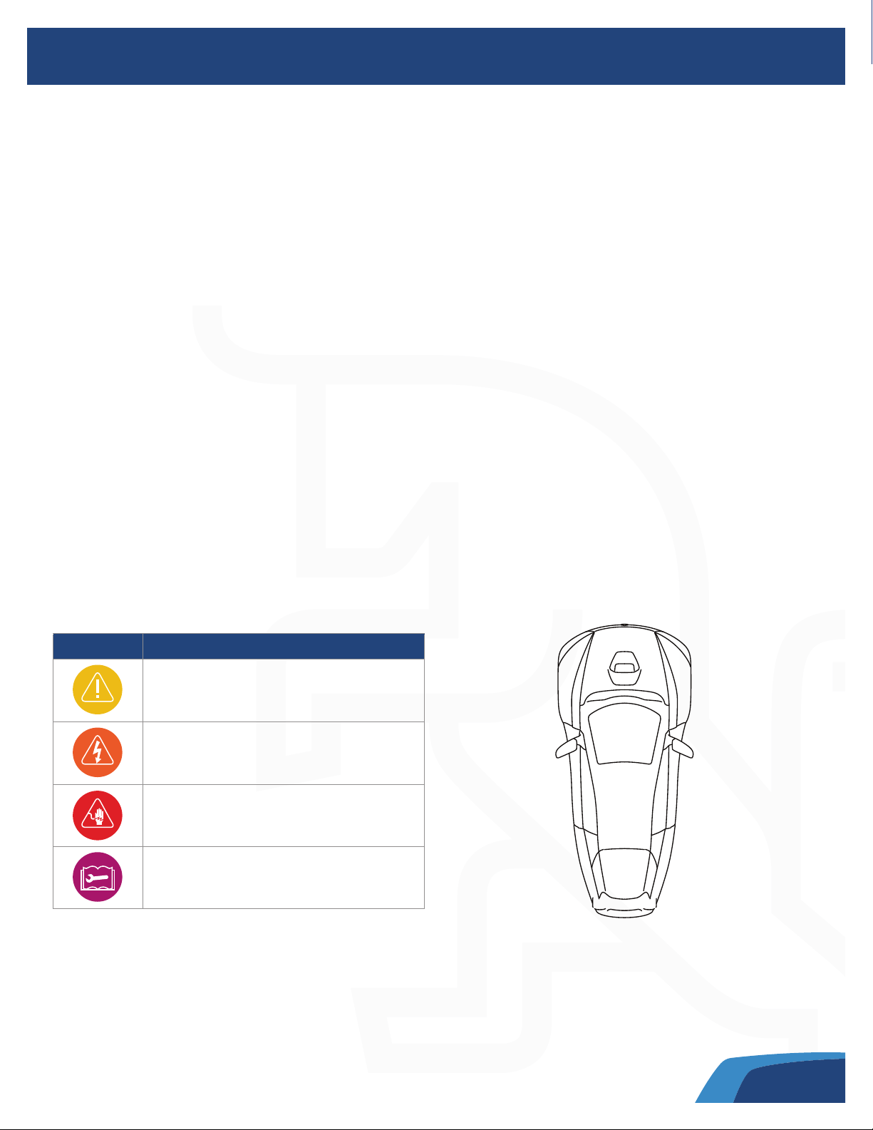
SYMBOL DEFINITION
Warning
Risk of electric shock; use caution
Risk of electric shock; use caution
Refer to instructions/manual
This guide describes first response operations and important safety-related warnings that must be followed when
handling this vehicle in an emergency situation.
This electric vehicle is equipped with a high-voltage battery pack. Failure to follow recommended practices
during emergency responses can cause death or serious personal injury.
Please read this guide in advance to understand the features of this vehicle and to help you deal with incidents
involving this vehicle. Follow the procedures to help ensure a safe and successful first response operation.
This guide covers the SOLO vehicle for models manufactured in 2021 or newer. This manual may be
periodically updated. If you are not viewing this manual on the ocial ElectraMeccanica web site, go to
electrameccanica.com/firstresponders or electrameccanica.com to ensure you have the most recent version.
The terms Right or Left refer to the driver’s right or left while
sitting in the vehicle. The following cautionary symbols may be
found on labels throughout the vehicle.

PG. 3
SAFETY INFORMATION
SYMBOLS GLOSSARY
Indicates a hazard with a high level of risk which will result in serious injury or death
Indicates a hazard that could result in injury or death
Indicates a hazard that could result in property or vehicle damage
Note: Indicates additional information, hints, and tips.
The following symbols used within this manual call your attention to specific types of hazards and what to do to
avoid or reduce them.
DANGER
WARNING
CAUTION

PG. 4
IDENTIFYING THE SOLO
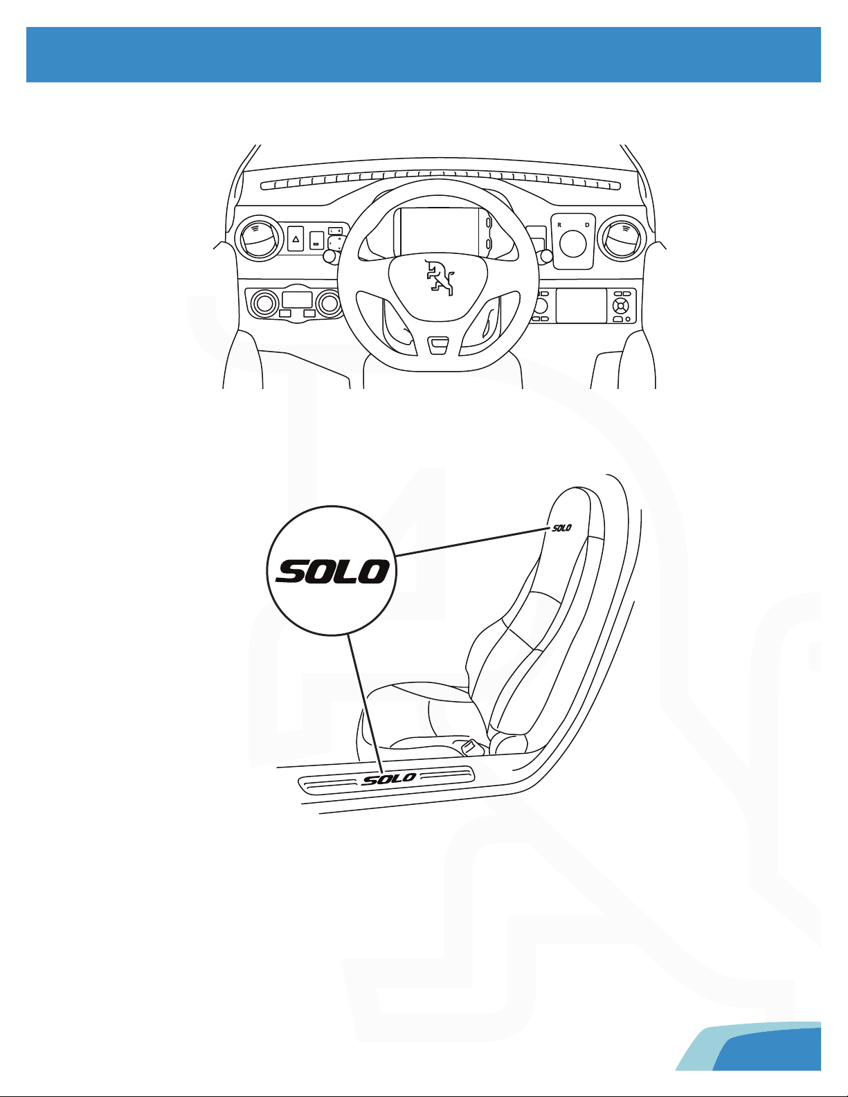
The SOLO is a three-wheeled, single-passenger vehicle. The exterior can be distinguished by its unique badging.
EXTERIOR
PG. 5
Both the seat and the rocker panels in the door frames have SOLO badging.
MIRROR
IDENTIFYING THE SOLO
INTERIOR
The SOLO can be identified from the interior by its unique dashboard layout and instrument cluster display screen.
PG. 6
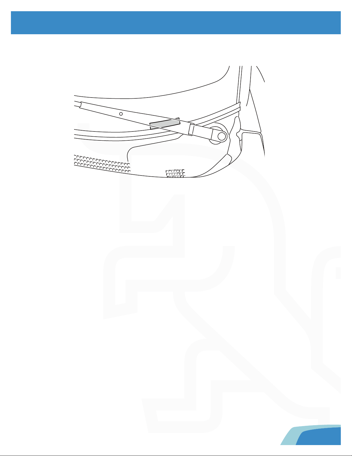
IDENTIFYING THE SOLO
This legal identifier is in the front corner of the instrument panel. It can be viewed from outside the vehicle.
The VIN is also printed on the Tire and Loading Information Label (see “Vehicle Weight Information”, page 33).
VEHICLE IDENTIFICATION NUMBER (VIN)

PG. 7
IMMOBILIZING & STABILIZING THE VEHICLE
SHIFTING INTO NEUTRAL
R- Reverse
N- Neutral (Use when starting, parking, or transporting the vehicle)
D- Drive
The Drive Mode Selector is a three-position dial on the dash. When the key switch is ON, the Drive Mode
Selector can be used to set the desired direction of the vehicle:
The current selection is illuminated on the dial, and is also indicated on the instrument
cluster display.

PG. 8
IMMOBILIZING & STABILIZING THE VEHICLE
P
The EPB has both manual and automatic functions. It is manually controlled by a rocker switch on the dash, to the
right of the steering wheel.
Using the EPB manuallyTo activate or deactivate the EPB manually:
1.Ensure that the vehicle is moving at less than 2 mph (3 km/h) and the key switch is in the ON position.
2.To activate the EPB, pull out the EPB switch.
3.To deactivate the EPB, press the brake pedal and push in the EPB switch.
Note: The EPB can only be activated or deactivated manually when the vehicle's speed is less than 2 mph (3km/h) and
the key switch is in the ON position.
Note: The EPB can be engaged in any Drive Mode Selector position.
When the EPB is engaged either manually or automatically, the EPB indicator will illuminate on the
instrument cluster display.
APPLYING THE ELECTRONIC PARKING BRAKE (EPB)
See “Using the Key Switch”, page 22.

PG. 9
IMMOBILIZING & STABILIZING THE VEHICLE
The EPB has a special Maintenance Mode, which allows it to remain disengaged while the vehicle is OFF,
overriding the automatic function until the vehicle is turned ON again.
To enter EPB Maintenance Mode, first disengage the park brake manually. When the vehicle is NOT started
(READY message is NOT illuminated on the dash):
When the EPB Maintenance Mode is activated, a system message will be displayed on the instrument
cluster display.
EPB MAINTENANCE MODE
1. Press and hold the brake pedal.
2. Push in and hold the EPB switch continuously for 30 seconds. The EPB indicator will illuminate on the
instrument cluster display.
Note: If the 30-second long push of the EPB switch is interrupted, you must repeat it for the full 30 seconds.
Then enter Maintenance mode with the following steps:
1. Press and hold the brake pedal.
2. Push in and hold the EPB switch continuously for 30 seconds. The EPB indicator will illuminate on the
instrument cluster display.
Note: If the 30-second long push of the EPB switch is interrupted, you must repeat it for the full 30 seconds.
3. Turn the key switch to the OFF position.
To exit Maintenance Mode, use either option:
•
•
Turn the key switch ON, press the brake pedal, then pull out the EPB switch.
Turn the key switch ON, then OFF. Once the vehicle is keyed ON, the automatic functions of the EPB will
resume, and it will engage automatically when the key switch is turned OFF.
Use caution when disengaging the EPB, as the vehicle will be free-rolling. Be aware that
the vehicle could roll if it is not on a level surface.
Pushing the vehicle with wheels on the ground should only be done for very short distances,
as prolonged rolling (e.g. towing with wheels on the ground) can cause heat damage to the
drive motor system and generate high voltages in the electrical system.
WARNING
CAUTION
Park Brake
Maintenance Mode
PG. 10
IMMOBILIZING & STABILIZING THE VEHICLE
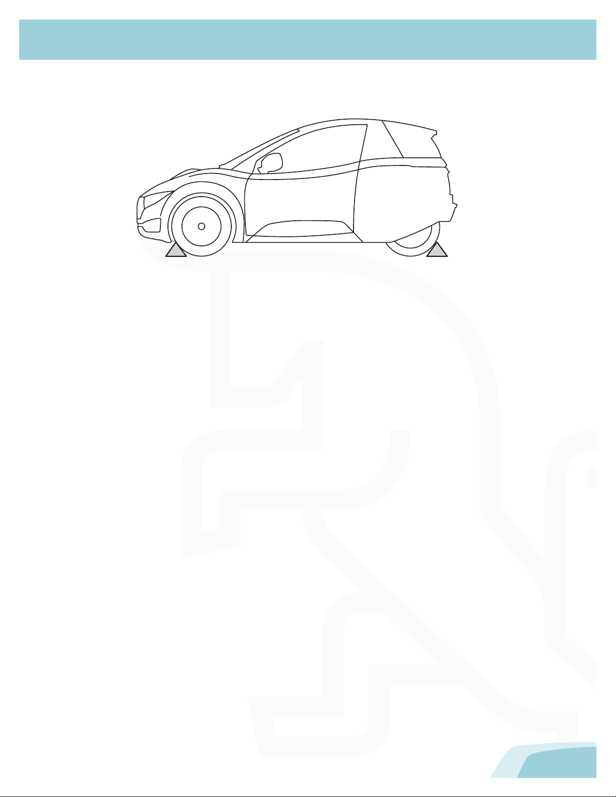
CHOCKING THE WHEELS
To help prevent the vehicle from moving, always chock all three wheels before attempting extraction procedures.
•Electric vehicles run and drive silently, so never assume they are powered o.
•When the Drive Mode is in D (Drive) or R (Reverse), this vehicle will creep forward or backward while the
drive system is powered on and the brakes are not engaged.

PG. 11
ELECTRICAL SYSTEM INFORMATION
HIGH-VOLTAGE COMPONENTS
A/C compressor
High-voltage batteries
On-board charger
Powertrain controller
Charging port
Charging cable
DC/DC converter
Drive motor
High-voltage distribution box
Cabin heater
Battery heater
1
2
3
4
5
6
9
10
11
7
8
9
10
11
7
8
1
2
2
3
4
56

PG. 12
ELECTRICAL SYSTEM INFORMATION
HIGH-VOLTAGE WARNING LABELS
Illustrated above are examples of some of the high-voltage warning labels that can be found on high-voltage
components within the vehicle. These labels are one way to quickly identify potential electrical hazards. For your
safety, always follow all cautions and instructions on warning labels.Labeled high-voltage components include (but
are not limited to):
•High-voltage batteries (both tubes)
•DC/DC converter
•High-voltage distribution box
•A/C compressor
High Voltage
Follow Lockout Procedure
Before Removing The Cover
WARNING
High Voltage!
Service by Authorized
Personnel Only
DANGER
Not all high-voltage components are labeled. Always wear appropriate PPE when
cutting the vehicle. Failure to do so can result in death or serious injury.
WARNING

PG. 13
ELECTRICAL SYSTEM INFORMATION
HIGH-VOLTAGE BATTERIES
The 144V lithium-ion batteries are encased and mounted under the vehicle floor.When using lifting or rescue
tools, use caution and never breach a high-voltage battery case. For proper lifting procedures, see “Lifting the
Vehicle”, page 27.
Li-ion
Li-ion
Li-ion

PG. 14
ELECTRICAL SYSTEM INFORMATION
12-VOLT BATTERY
The 12V battery is located at the right front of the chassis, to the right of the accelerator pedal. This battery
powers all of the standard low-voltage electronics in the vehicle. It also powers the high-voltage distribution box,
which controls high-voltage current within the high-voltage components (e.g. drive motor, powertrain controller).

PG. 15
ELECTRICAL SYSTEM INFORMATION
HIGH-VOLTAGE CABLES
High-voltage cables are colored orange for easy identification.

PG. 16
ELECTRICAL SYSTEM INFORMATION
DRIVE MOTOR
1
The drive motor (1) is located near the rear wheels of the vehicle. This component receives 3-phase alternating
current (AC) and converts it into propelling energy (torque), used to power the wheels.

PG. 17
OPENING THE VEHICLE
HOOD
TRUNK
1
2
1. Pull the handle (1) located on the side panel under the lower left corner of the dash.
2. Lift the secondary catch release lever (2) under the front lip of the cover and raise the hood.
Pushing the trunk release button on the dash will open the trunk.
Note: The remote transmitter can also be used to open the trunk.
Note: The trunk release button on the dash is disabled when the vehicle is locked with the remote transmitter.

PG. 18
OPENING THE VEHICLE
EMERGENCY TRUNK RELEASE
If the vehicle has no power, the trunk can be opened manually from the inside:
1. Remove the cover at the base of the trunk latch.
2. Pull the emergency release handle to unlatch the trunk.
Other manuals for SOLO
1
Table of contents


