Contents
4
Contents
Introduction .........................................................................................................................5
Technical support .............................................................................................................5
Spare parts.......................................................................................................................5
Warranties ........................................................................................................................5
Maintenance.....................................................................................................................5
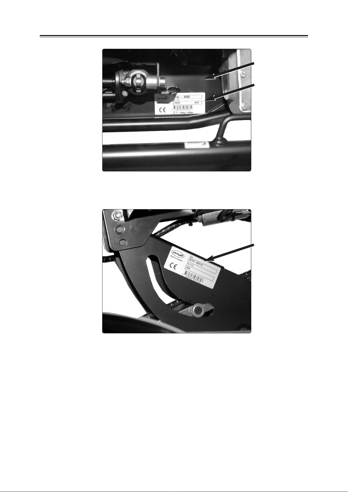
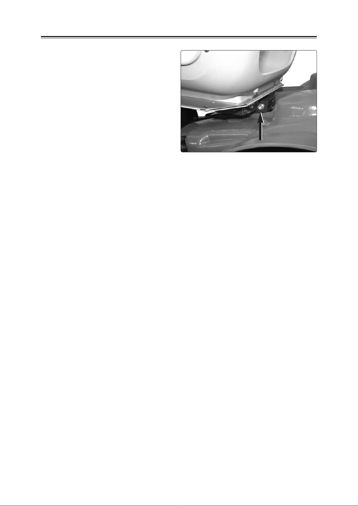
Rating plates........................................................................................................................6
Raising the seat lift .............................................................................................................7
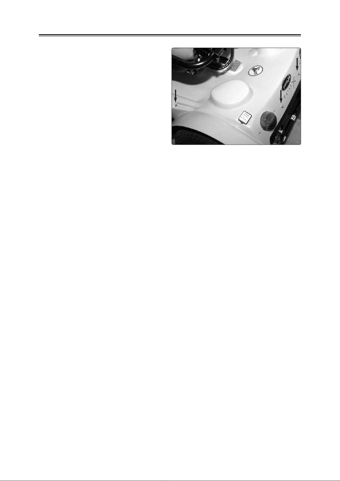
Covers ..................................................................................................................................8
Changing the batteries .......................................................................................................10
Removal ...........................................................................................................................10
Fitting ...............................................................................................................................11
Changing the drive wheel ..................................................................................................12
Changing the brake release wires.....................................................................................14
Changing/adjusting the magnetic brake...........................................................................16
Changing the drive motor ..................................................................................................19
Removal ...........................................................................................................................19
Fitting ...............................................................................................................................21
Changing the carbon-brush in the drive motor ...............................................................23
Removal of the carbon-brush...........................................................................................23
Fitting the carbon-brush ...................................................................................................24
Changing the seat lift motor ..............................................................................................25
Changing the seat lift .........................................................................................................26
Removal ...........................................................................................................................26
Fitting ...............................................................................................................................27
Changing the bush in the front/rear wheel assembly .....................................................28
Steering knuckle spring mounting in the front wheel assembly ...................................30
Manual steering (moving between the right and left sides) ...........................................32
Changing the steering wire (adjustment) - front wheel adjustment (Toe-in) ................33
Power steering (adjustment)..............................................................................................35
Potentiometer, front wheel assembly ...............................................................................36
Changing the lights/indicators ..........................................................................................37
Changing the wheel base (manually)/Electrical wheel base adjustment ......................38
Bumper positions................................................................................................................40
Pinch protection switch......................................................................................................41
Changing the seat swivel direction (manually/electrically) ............................................42
Changing the cable of the lights potentiometer ..............................................................43
Changing/moving the charging socket.............................................................................45
Changing the electronics (Safe Gate) ...............................................................................46
Changing the jack panel.....................................................................................................47
Changing the fuses in the electronics and jack panel....................................................48
"Battery cut-out" main fuse ...............................................................................................49
Accessories (bows, luggage basket/box, crutch holder, rear-view mirror) ..................50
Cable laying .........................................................................................................................56
Wiring diagram ....................................................................................................................58