Electra e9 User manual

1
electra e9
DETECTOR MOVIMENTO
ENCASTRAR 180º 3 fios
INTRODUCTION
e9 é um detector de movimento para montagem
encastrada na parede que usa um sensor interno
infravermelhos para detector alterações de
temperature emitidas por pessoas que passem na
sua area de detecção.
O detector vai manter o circuito de iluminação ligado
enquanto detector movimento na sua area de
detecção.
Nota: Por favor lei-a atentamente todo o manual
antes de começar a instalar a unidade.
VISÃO GERAL DO EQUIPAMENTO
Unidade PIR
Unidade encastravel de ligações
Terminais de ligação
Lente
Indicador LED
Potenciometros TIME & LUX (tempo e
luminosidade)
PRECAUÇÕES DE SEGURANÇA
Evitar instalar a unidade com ambiente de chuva
e trovoada.
Certifique-se de isolar ou desligar a corrente
antes da instalação da unidade.
Asegure-se que o circuite está protegido por um
disjuntor.
IMPORTANTE
A instalação deve ser feita por pessoal
especializado.
Certifique-se dos códigos locais pois conferem com
a sua situação. Se a instalação da sua casa for de
aluminium fale com o seu electricista
sobre os
métodos proprios.
Antes de iniciar a instalação desligue o referido
circuito no disjuntor para evitar um choque
electrico.
ESCOLHA DA LOCALIZAÇÃO DE
MONTAGEM
O detector efectuará uma melhor detecção na parede
virado para a passagem ou entrada principal assim o
movimento das pessoas é facilmente detectado.
(FIGURA 1)
FIGURA 1
Quando decider escolher um local próprio para a
instalaçao do detector, por favor tome atenção aos
seguintes pontos:
O detector deve ser montado no interior num
local seco somente.
A unidade foi desenhada para instalação em
caixa de aparelhagem na parede e não no tecto.
Evite instalar o detector perto de fontes de calor
tais como unidades de ar condicionado ou outros.
Não instale a unidade em que fique directamente
a apanhar luz solar no seu corpo.
O detector é mais sensivel quando apanha no
seu raio de visão um objecto a deslocar-se
transversalmente. É menos sensivel quando o
objecto se dirige directamente para a cabeça da
unidade. (FIGURA 2)
Vista traseira
do detector
PIR

2
Mais sensivel Menos sensivel
FIGURA 2
A posição recomendada para a instalação do
detector é na parede (encastrável) a uma altura
entre 1.5~1.8 metros. A esta altura o detector
vai optimizar o seu alcance até 12 metros (linha
recta) com um campo de 160°e 3 metros com
um campo de 180°. (FIGURA 3a & 3b)
1.8m
FIGURA 3a
FIGURA 3b
INSTALAÇÃO
(1) Desligue a corrente ou o interruptor que controla
o circuito antes de iniciar a instalação.
(2) O detector foi desenhado para ser encastrado
numa cx de aparelhagem. Para instalar a
unidade primeiro separe o corpo frontal da fonte
de alimentação. (FIGURA 4)
FIGURA 4
(3) Insira 2 parafusos (fornecidos) no corpo da fonte
de alimentação para fixar a unidade. A seguir
insira o corpo frontal da unidade. Note que a
junta que sai do corpo frontal deve entrar
alinhada na fonte de alimentação sem ser
forçada. (FIGURA 5)
FIGURA 5
INSTRUÇÕES CABLAGEM
(1) Desligue a corrente ou o interruptor que controla
o circuito antes de iniciar a instalação.
(2) Separe o corpo frontal da unidade fonte de
alimentação. (FIGURA 4)
(3) Na unidade fonte de alimentação pode encontrar
os terminais numerados. (FIGURA 6)
FIGURA 6
(4) Veja a FIGURA 7 para informação de ligação.
Depois descarne os cabos e ligue-os de acordo
com o esquema da FIGURA 7.
ATENÇãO: uma ligação mal feita pode
danificar a unidade e mesmo resultar num
choque electrico !.
Vista topo
Vista lateral
Junta de
terminais

3
FIGURA 7
Nota: o interruptor 1 (SW1) é o interruptor na parede
para operação manual. O interruptor 2 (SW2) é para
desencadear manualmente a ligar (semi-auto).
Consulte a secção de OPERAÇÃO para obter mais
detalhes.
TESTE / AJUSTE DE CONFIGURAÇÕES
(1) TESTE O DETECTOR
Rode os potenciometros Time e LUX sentido
anti-horário para a posição “T” (TEST).
(FIGURA 8)
FIGURA 8
Ligue ou alterne a fonte de alimentação e o
detector levará cerca de 40-60 segs para aquecer.
Após o aquecimento, a luz apaga-se.
Caminhe através da area de cobertura e a luz irá
acender-se. Isto confirma que as ligações foram
bem executadas e que a iluminação está a
funcionar. A luz acende-se por cerca de 5 segs e
depois desliga-se. Aguarde até que a luz se
apague e depois passe novamente para testar o
detector.
(2) CONFIGURAÇÕES
AJUSTE DO TEMPO
O potenciometro TIME determina quanto tempo a
luz permanence acesa após a detecção de
movimento.
Rode o potenciometro TIME sentido horario para
aumentar o tempo de acendido (até 30 minutos).
Rode o potenciometro para a esquerda para
diminuir a duração (15 seg). Defina o tempo de
configuração de acordo com as suas
necessidades. (FIGURA 9)
cerca de 15 segundos cerca de 30 minutos
FIGURA 9
AJUSTE DA LUMINOSIDADE (LUX)
O ajuste LUX determina em qual nível de luz
ambiente a luz artificial irá ser ligada.
FIGURA 10
Por exemplo, rode o potenciometro para a
posição da “LUA” (FIGURA 10) e a luz só ligará
no ponto mais baixo de iluminação (abaixo dos 20
Lux).
Quando a luz ambiente é o nivel de preferencia
para acender a luz artificial, rode lentamente o
potenciometro LUX sentido anti-horário para
aumentar a configuração LUX. Faça movimentos
durante o processo. Quando a luz acender quer
dizer que o nível preferido LUX foi atingido.
A gama LUX ajustável é de cerca de 20-300 LUX.
Defina a configuração LUX de acordo com as
suas necessidades.
OPERAÇÃO
Operação Automática
Quando o detector detecta movimento e o nível
de luz ambiente é mais baixo do que a
configuração LUX, a luz liga automaticamente. A
luz fica acesa durante a duração do ajuste do
TIME e em seguida desliga. Observe que, se o
movimento é detectado novamente enquanto a
luz estiver acesa, a contagem do tempo será
reiniciado.
O sinalizador LED da unidade também ira ligar
quando o relé esta ligado (acionado pelo
movimento).
alimentação
SW2
carga
SW1
T
LUA

4
Operação de sobreposição manual
Para manter a luz acesa, independentemente do
movimento, pode substituir a operação
automatica. Para activar o modo de acionamento
manual, em primeiro lugar certifique-se que o
detector esta no modo automatico. Em seguida,
desligue o interruptor (SW 1 na FIGURA 7) duas
vezes (off-on, off-on) em 4 seg para entrar no
modo de cancelamento manual. O intervalo entre
a primeira e segunda operação deve ser dentro
de 0.5 - 2 seg.
No modo de acionamento manual, a luz
permanecerá acesa por cerca de 5 horas. Após
as 5 horas, a luz apaga-se e o sensor de
movimento será revertido para o funcionamento
automático.
O utilizador também pode configurar
manualmente o detector de movimento de volta
ao funcionamento automatico, desligando o
interruptor de parede por pelo menos 10 seg.e
em seguida, ligá-lo novamente.
Operação manual de acionamento
Em alguns casos, o utilizador pode querer activar
a luz manualmente, sem entrar no modo de
sobreposição manual. Para tais requisitos
“semi-auto” pode alternar o acionamento no
interruptor (SW2 na FIGURA 7) para ligar
manualmente a luz. A luz fica acesa durante a
duração do ajuste do TIMEe, em seguida desliga.
O detector volta ao modo automatico.
SOLUÇÃO DE PROBLEMAS
A luz não liga (mesmo com o LED aceso na
unidade)
Confirme que ligou bem a unidade.
Confirme que as lampadas estão boas.
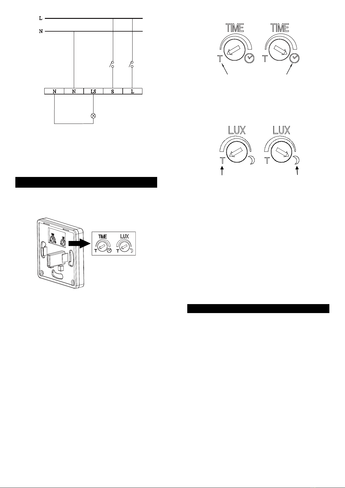
Confirme que a configuração do Lux está
correcta.
Luz fica acesa
Confirme que ligou bem a unidade.
Confirme que a configuração do TIME está
correcta.
Confirme se a unidade se encontra no modo de
operação de cancelamento manual.
ESPECIFICAÇÕES
Alimentação
AC 220 - 240V / 50Hz
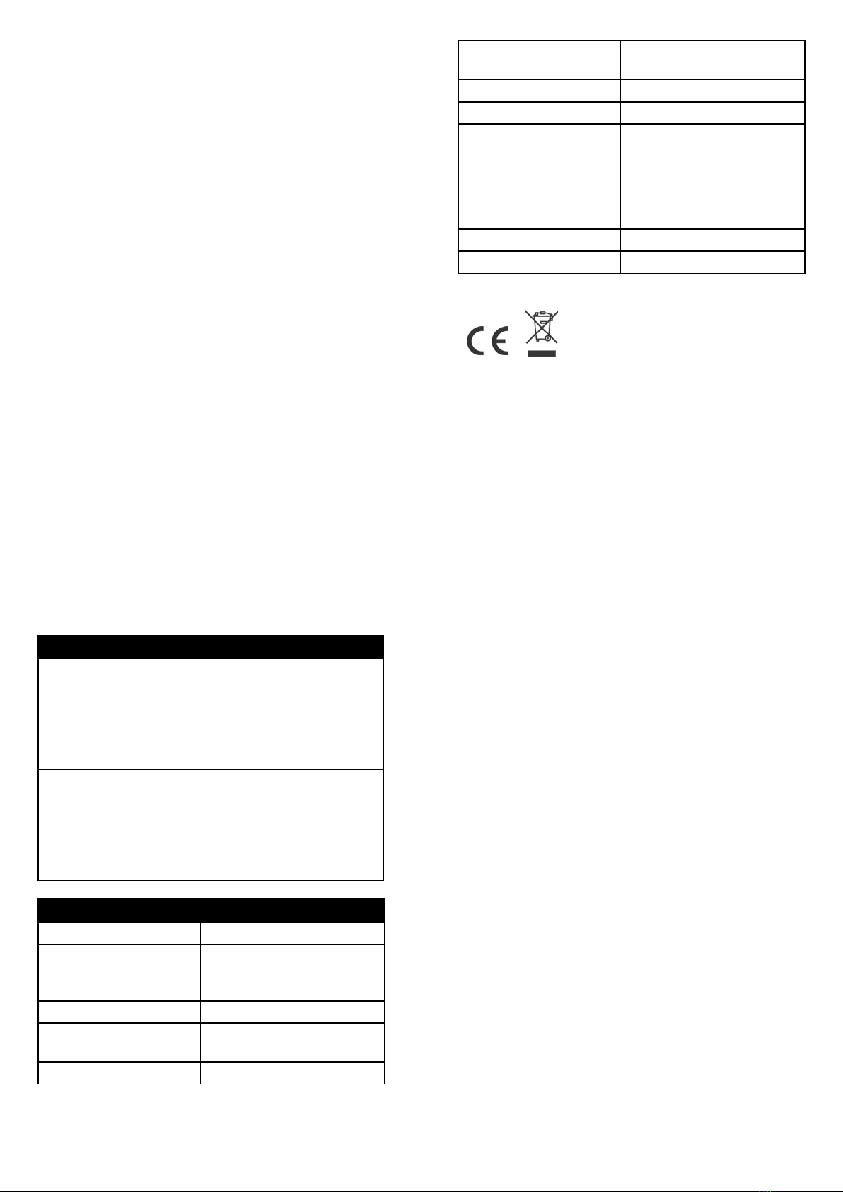
Carga Maxima 1000W incandescente
500W fluorescente
360W LED
Angulo detecção
até 180°(horizontal)
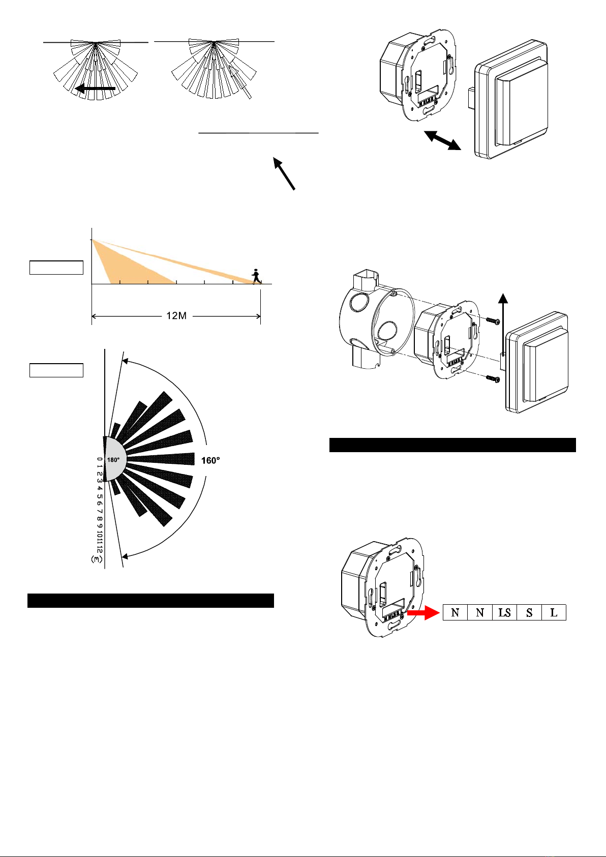
Distancia detecção a
1.8m altura
até 12m (linha recta) a
20°C
Altura montagem
Recomendado 1.5 – 2.0m;
Encastrável em cx de
aparelhagem
Operação do detector
Auto / Manual
Tempo de ajuste
15 sec. - 30 min.
Lux de ajuste
20 - 300 Lux
Aquecimento
Menos de 1 minuto
Temperatura de
operação
0°C - +45°C
Classe de protecção
Class II
Estanquecidade
IP40
Segurança
CE
*as especificações podem ser alteradas sem aviso prévio.
AVISO:
Não deite for a as unidades electricas junto com o lixo
normal. Use sempre os recipientes de acordo.
Contacte os centros de recolha para o efeito ou pode
sempre devolver a unidade onde a adquiriu.
Se os produtos electricos forem lançados nos campos
estes poderão verter componentes que irão
contaminar o solo e águas e futuramente prejudicar a
sua saúde.
Quando substituir aparelhos antigos por novos a loja
terá de aceitar as unidades antigas sem qualquer
custo.
electra.pt
2665-601 VENDA DO PINHEIRO
PORTUGAL

1
electra e9
RECESSED WALL MOUNT
MOTION SENSOR
INTRODUCTION
electra e9 is a recessed wall mount motion sensor
that uses a passive infrared sensor to detect changes
in temperature emitted by persons passing through its
detecting area.
The sensor will keep the connected lighting fixture on
as long as motion is detected in its detection range.
Note: Read this entire manual before you start to
install the system.
PRODUCT OVERVIEW
PIR Detection Unit
Recessed Power Unit
Wiring Terminals
Lens
LED Indicator
TIME & LUX Control Knobs
SAFETY PRECAUTIONS
Avoid installing the unit in storming or raining
weather.
Be sure to isolate or switch off power source
before installing or maintenance.
DO ensure that the power supply circuit is
protected by a 16 amp circuit breaker or suitable
equivalent fuse.
IMPORTANT
Installation and wiring must be performed by skilled
technicians who are informed about the standards
and technical requirements of the appliance and its
proper installation.
Check your local codes as they apply to your
situation. If the house wiring is of aluminum,
consult with an electrician about proper wiring
methods.
Before proceeding with the installation, TURN OFF
THE POWER TO THE LIGHTING CIRCUIT AT
THE CIRCUIT BREAKER OR FUSE BOX TO
AVOID ELECTRICAL SHOCK.
CHOOSING A MOUNTING LOCATION
The motion sensor is best installed on a wall that
faces the main passage or entrance so the movement
of persons walking by can be easily detected.
(FIGURE 1)
FIGURE 1
When deciding a proper location to install the unit,
please take the following points into consideration:
The sensor is suitable for mounting indoor in dry
interior locations only.
The unit is designed for wall mount and is not
suitable for ceiling mount.
Avoid aiming the motion sensor at heating
sources, air conditioners or objects which may
change temperature rapidly.
Do not allow sunlight to fall directly on the body or
on the front of the unit.
The sensor is more sensitive to an object moving
across its field of view. It is less sensitive to an
object moving directly towards the sensor’s head.
(FIGURE 2)
Rear View of
PIR Detection
Unit

2
More Sensitive Less Sensitive
FIGURE 2
The recommended position for the motion sensor
is on the wall of a room mounted at a height of
1.5~1.8 meters. At this height, the sensor will
optimize the detection range of up to 12 meters
(straight line) with a field of 160°and 3 meters
with a field of 180°. (FIGURE 3a & 3b)
1.8m
FIGURE 3a
FIGURE 3b
INSTALLATION
(1) Switch off the power source or wall switch before
installing.
(2) The sensor is designed to be installed inside a
pattress box. To install the sensor, first detach
the detection unit from the recessed power unit.
(FIGURE 4)
FIGURE 4
(3) Secure the recessed power unit to the pattress
box using 2 screws supplied. Then fit the
detection unit back to the recessed power unit.
Note the joint post should align correctly with the
opening on the left side of the recessed power
unit. (FIGURE 5)
FIGURE 5
WIRING INSTRUCTION
(1) Switch off the power source or wall switch.
(2) Detach the detection unit from the recessed
power unit. (FIGURE 4)
(3) On the recessed power unit you can find the
wiring terminals. (FIGURE 6)
FIGURE 6
(4) Study FIGURE 7 for wiring information. Then
thread and fasten the power cables as indicated
in FIGURE 7.
Warning: Incorrect wiring could damage the
sensor or connected load, and also may
cause electrical harm.
Top View
Side View
Joint Post

3
AC Power
SW2
Load
SW1
FIGURE 7
Note: Switch 1 is the switch on the wall for manual
override operation. Switch 2 is for manually
triggering on (semi-auto) operation. Refer to
OPERATION section for more details.
TEST / ADJUST THE SETTINGS
(1) TEST THE SENSOR
Turn the Time and LUX controls counterclockwise
to the “T” (TEST) position. (FIGURE 8)
FIGURE 8
Connect or toggle on the power source and the
sensor will take about 40-60 seconds to warm up.
After warming up, the light will turn off.
Walk through the coverage area and the light will
turn on. This confirms that the wiring was done
properly and that the light is working. The light
will turn on for about 5 seconds and then turn off.
Wait until the light turns off and then move again
to test the sensor.
(2) SETTINGS
TIME ADJUSTMENT
The TIME control knob determines how long the
light will stay on after motion is detected.
Turn the TIME control knob clockwise to increase
the light-on time (up to 30 minutes).Turn the
control knob counterclockwise to decrease the
duration (down to 15 seconds). Set the time
setting according to your requirements. (FIGURE
9)
About 15 Seconds About 30 Minutes
FIGURE 9
LUX ADJUSTMENT
The LUX adjustment determines at what ambient
light level the light will start operating.
FIGURE 10
For instance, turn the control knob to the MOON
position (FIGURE 10) and the light will only turn
on at low illumination (below 20 Lux).
When the ambient light is the preferred level for
turning the light on, slowly turn the LUX control
knob counterclockwise to increase the Lux setting.
Keep creating motion during the process. When
the light is on, it means the preferred Lux level is
set.
The adjustable Lux range is about 20 - 300 Lux.
Set the Lux setting according to your
requirements.
OPERATION
Automatic Operation
When the sensor detects motion and the ambient
light level is lower than the LUX setting, the
connected light will automatically turn on. The
light will stay on for the duration of TIME setting
and then turn off. Note that if motion is detected
again while the light is still on, the time counting
will be reset.
The LED indicator on the unit will also turn on
when the relay is on (triggered by motion).
Manual Override Operation
To keep the light on regardless of the motion, you
can override the Automatic Operation. To
enable Manual Override mode, first ensure that
the sensor is in Automatic Operation mode.
Then turn the wall switch (Switch 1 in FIGURE 7)
T
MOON

4
off and on twice (off-on, off-on) within 4 seconds
to enter Manual Override mode. The interval
between the first and second operation must be
within 0.5 - 2 seconds.
In Manual Override mode, the light will remain on
for around 5 hours. After 5 hours the light will turn
off and the motion sensor will revert to Automatic
Operation.
Users can also manually set the motion sensor
back to Automatic Operation by turning off the
wall switch for at least 10 seconds and then
turning it back on.
Manual Trigger Operation
In some cases the user may want to activate the
light manually without entering Manual Override
operation. For such semi-auto requirements you
can toggle the trigger switch (Switch 2 in FIGURE
7) on to manually turn on the light. The light will
stay on for the duration of TIME setting and then
turn off. The motion sensor will then return to
Automatic Operation.
TROUBLESHOOTING
Light does not turn on (even though the LED indicator
on the unit is on)
Confirm that you have made a correct wiring
connection.
Make sure that the bulbs have not burned out.
Make sure the Lux setting is correct.
Light remains on
Make sure the wiring connection is correct.
Check if the TIME setting is correct.
Check if the unit is in Manual Override operation.
SPECIFICATIONS
Power Requirement
AC 220 - 240V / 50Hz
Max. Lighting Load 1000W incandescent;
500W fluorescent;
360W LED lamps
Detection Angle
Up to 180°(horizontal)
Detection Distance at
1.8m Height
Up to 12m (straight line) at
20°C
Mounting Height
Recommended 1.5 – 2.0m;
Recessed Wall Mount;
(the unit should be installed in a
pattress box)
Sensor Operation
Auto / Manual override
Time Adjustment
15 sec. - 30 min.
Lux Adjustment
20 - 300 Lux
Warm Up Time
Less than 1 minute
Working Temperature
0°C - +45°C
Protection Class
Class II
Protection Degree
IP40
Safety
CE
*Specifications are subject to change without notice.
Warning:
Do not dispose of electrical appliances as unsorted
municipal waste, use separate collection facilities.
Contact your local government for information
regarding the collection systems available.
If electrical appliances are disposed of in landfills or
dumps, hazardous substances can leak into the
groundwater and get into the food chain, damaging
your health and well-being.
When replacing old appliances with new ones, the
retailer is legally obligated to take back your old
appliance for disposal at least for free of charge.
Table of contents
Languages:
Other Electra Accessories manuals