English 3
2. SELECTING THE LOCATION OF UNITS
Only trained and qualified service personnel recommended by the company should install the air conditioner,
in pursuance of the company specifications and using pipes, wiring, and the standard installation
accessories of the company. Any service call, maintenance or repair carried out by the company on
equipment that was installed in noncompliance with the company's instructions will require payment.
In selecting the location of the units, the following requirements should be taken into account:
2.1 Relative location of the units
Install the outdoor unit (condenser) and the indoor unit (evaporator) as close as possible to each other.
For determining the maximum permitted distance between them, see page 8. If it is necessary to
exceed this distance, consult the company.
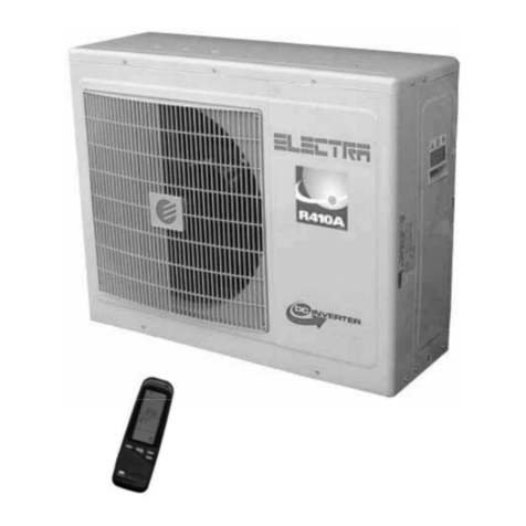
2.2 Selecting the outdoor unit (condenser) location
• Allow sufficient space for servicing and air flow around the unit.
• Avoid the unit’s exposure to direct sunlight.
• Select a place for the unit that will cause minimum disturbance and/or inconvenience to the user
and the neighbors.
• A minimum of 200 mm is required between the unit and any wall.
• When installing in an enclosed space (balcony, laundry room etc.), make sure that there are vents
ensuring the release of the warm air outside and preventing its return into the outdoor unit.
• In the case of several outdoor units installed in a group, make sure that the warm air discharged by
one outdoor unit is not directed toward another outdoor unit.
• Make sure that the wall on which the outdoor unit is to be installed has a minimum thickness of 200
mm and is strong enough to support the weight of the unit. Do not install on a light structure that is
not resonance vibration-proof (for instance I-tung).
• When the outdoor unit is installed below the level of the indoor unit, ensure that the height
difference between the units is as explained on page 8.
• When installing on the balcony of a second floor or higher, make sure that the level of the upper
housing of the outdoor unit is at the height of the railing. If the outdoor unit is nonetheless installed
lower, ensure that it is installed in a way that will allow easy access and possibility of removing the
cover when servicing the unit.
• When the outdoor unit is installed in an alcove or in a place without free access, install tubing
longer than that usually required, with several loops, to allow for moving the unit when servicing.
• Take into account that water dripping occurs during the heating operation. If it disturbs neighbors,
ensure drainage.
• It is recommended not to hang outdoor units on bedroom walls.
• Do not install outdoor units on tile and asbestos roofs.
