Page 2
ASSEMBLY
HOW TO ASSEMBLE YOUR ELECTRABRAKE
Note: The machine is supplied upside down for assembly purposes.
1. Remove all parts from the crate with the exception of ELECTRABRAKE magnet body
assembly.
2. Find the 6mm Allen Key and fasteners supplied.
3. Use slings provided to remove the magnet body from the crate. Rest the body on wooden
blocks supplied.
4. Attach the feet to column by using the M10 x 16 button-head screws provided. Point the
pair of feet forwards ensuring that the safety tape is facing forwards. Ensure that the
joining seam on the column faces to the backwards.
5. On Models EB0625 and EB1000, fasten foot plate under front feet using M10 by 16 cap-
head screws with washers. Alignment is easier if foot mounting is not tightened until the
foot plate is fitted. The rear feet cap head screws can be adjusted to level the machine.
A foot plate is not supplied with the EB1250 machine. The machine is bolted directly to
the floor at the front feet.
6. Place the ELECTRABRAKE magnet body on the stand securing it with M8 x 16 cap head
screws. This would be best if lifted with a lifting facility or some assistance. On Models
EB0625 and EB1000 ensure that connector and wires are guided down the column as
the magnet body is lowered on to the stand.
7. On Models EB0625 and EB1000, connect the electromagnet to the electrical unit by
removing the rear access panel and plug the three pin connectors together. Refit access
panel.
8. On Model EB0625 using the M6 pan head screws and nuts, join the two halves of the
tray. Using M8 x 12 cap head screws attach tray to rear of machine. Fit rubber mat inside
tray. Attach backstop slides to the sides of tray. On Model EB1000 and EB1250, use two
M8 x 16 cap head screws to attach the two back stop bars. Slide the stop collars onto
each back stop bar. Fit rubber mat.
9. Using M8 x16 cap head screws attach the handle (s) to the bending beam. Before
attaching the handle on Models EB0625 and EB1000, slide it through the angle
indicating ring. On Model EB1250, slide stop collar to the top of the handle and tighten.
Fit the handle with angle scale to the right side.
10. On Model EB 1250 rotate the bending beam to 180°. Slide angle indicator unit on to
right handle. Attach the two arms to the indicator spindle at the anchor block. To ensure
correct operation, securely fasten screws to switch mechanism.
11. Use solvent i.e. turpentine to remove the clear protective coating from the top of the unit
and from the clamp bar.
12. Place the clamp bar on the magnet body.
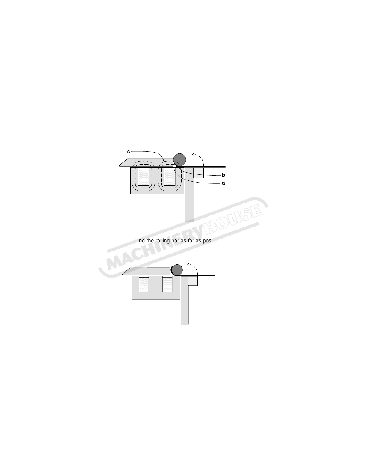
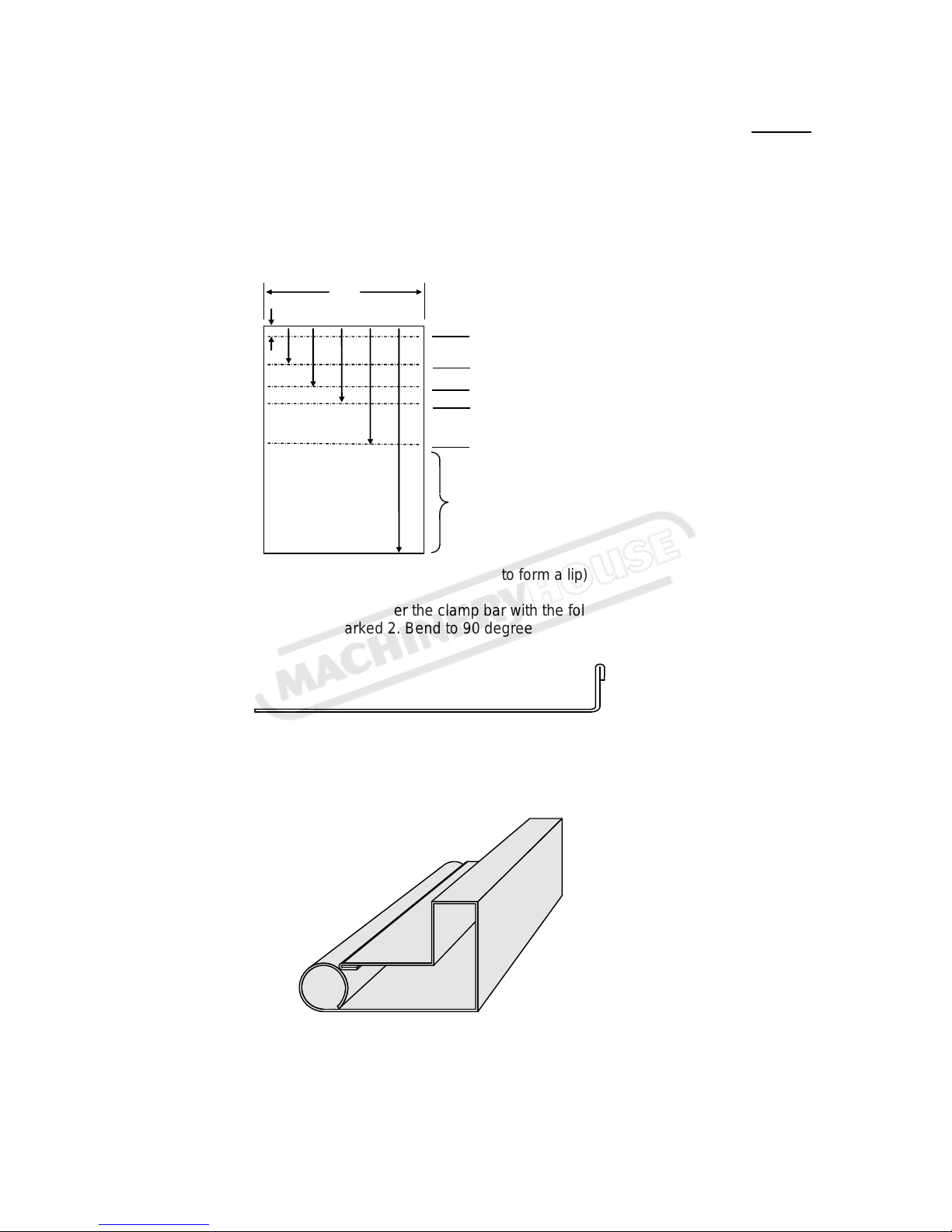
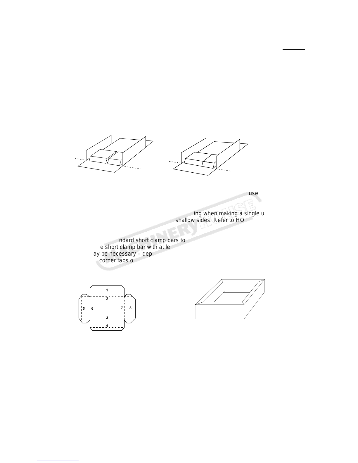
13. To obtain excellent results follow the operating instructions.
Instruction Manual for MB1250 (K8303)