Electric Blue Motors Blue Window Specification sheet

B L U E W I N D O W O P E R A T I O N A N D I N S T A L L A T I O N M A N U A L
Rev B – 8/12/09
E
LECTRIC
B
LUE
M
OTORS
Blue Window
Blue WindowBlue Window
Blue Window
–
––
–
Dashboard Computer
Dashboard ComputerDashboard Computer
Dashboard Computer
Operatio a d I stallatio Ma ual
Electric Blue Motors
4402 E. Huntington Drive Fl gst ff, AZ 86004
Phone 928.527.4662 • F x 928.527.466
www.electricbluemotors.com

B L U E W I N D O W O P E R A T I O N A N D I N S T A L L A T I O N M A N U A L
Table of Co te ts
S E C T I O N 1
I troductio
……………………1
Overview…………….….………….1
S E C T I O N 2
Packi g List
………..….……..2
S E C T I O N 3
Specificatio s
…….….……..3
S E C T I O N 4
I stallatio
………….…………4
a) Isolated Battery & Shu t
Co ectio s……………........6
b) 12V Car
Battery…………………..……..8
c) Tachometer Sig al
I put……………………………..9
d) Temperature Se sor
I put..………………..……..…11
e) Video Output……….……….12
S E C T I O N 5
Programmi g
………………..14
S E C T I O N 6
Usage
………………….…………16
S E C T I O N 7
Capacity Algorithm
…..….17
A P P E N D I X A
Schematic
…………..……..….18
A P P E N D I X B
E closure Drawi g
……….19
A P P E N D I X C
E closure Mou ti g
.…….20
A P P E N D I X D
Labeled Parts
………....…….21
Warning! Read ALL of the instructions before
attempting installation. All connections should be
made when the system is OFF. No connections
of energized wires should be made.

B L U E W I N D O W O P E R A T I O N A N D I N S T A L L A T I O N M A N U A L
- 1 -
1. I troductio
NOTE: It is important that you read this manual
before installing or operating any of these components.
Th nk you for purch sing Electric Blue Motors’ Blue
Blue Blue
Blue Window
WindowWindow
Window.
This m nu l covers oper ting nd inst ll tion inform tion for
the Electric Blue Motor’s Blue
Blue Blue
Blue Window
WindowWindow
Window.
he Blue Window is st te-of-the- rt electric vehicle
computer. It is used to monitor b ttery st te-of-ch rge,
RPMs, b ttery current nd b ttery volt ge. The Blue Window is
designed so th t the b ttery monitoring is completely isol ted
from the regul r c r 12V system. The Blue Window is powered by
the Propeller chip from P r ll x (www.p r ll x.com). The
Propeller is n 8 core 32-bit microprocessor th t is c p ble of
outputting composite video. M ny options in the Blue Window
re progr mm ble nd c n be customized for your c r.
Sectio
1
T

B L U E W I N D O W O P E R A T I O N A N D I N S T A L L A T I O N M A N U A L
2
2.
Packi g List
(See Appe dix D. Labeled Parts)
lease verify that all items on the acking List are in the box.
Any shortages should be reported immediately. Your Blue
Blue Blue
Blue
Window
WindowWindow
Window should include the following items:
•1x – Blue Window 225 Dashboard Computer
•1x – I
2
C Temperature Sensor
•2x – Inline fuse holders
•2x – 1A fuses
•1x – Composite video cable
•1x – 2 in Mating Connector
•2x – 4 in Mating Connectors
•1x – Shunt wire set
•1x – roximity Switch
•2x – Round 3/8” Magnet
•1x – Installation Guide & User’s Manual
Sectio
2

B L U E W I N D O W O P E R A T I O N A N D I N S T A L L A T I O N M A N U A L
3
3. Specificatio s
Items Displ yed............................Volt ge, Current, Motor Speed nd
B ttery C p city
Computer Power……………...8-20V, 20mA
B ttery Volt ge…………..…....36-250V
Shunt Input…………..……….500A = 50mV
T chometer……..…………….0-8000 RPM
B ttery Types Supported…...…Flooded Le d Acid, Gel/AGM
Le d Acid nd Lithium
Video Output………………....Composite Video, Color, NTSC
RS-170
Progr mming Port…………....Asynchronous Seri l, TTL levels,
115200, n, 8, 1
Sectio
3

B L U E W I N D O W O P E R A T I O N A N D I N S T A L L A T I O N M A N U A L
4
4. I stallatio
ALWAYS USE HIGH CAUTION WHEN WORKING ON
AN ELECTRIC VEHICLE. ALWAYS DISABLE THE
CIRCUIT BREAKER WHEN THE ENGINE BAY IS
O EN (THIS WILL HEL MINIMIZE RISK OF
SHOCK). ALWAYS TAKE NOTE WHERE THE
HIGH VOLTAGE LINES ARE.
he Blue Window is designed to m ke inst ll tion e sy. All of
the connections on the Blue Window re m de with
convenient plugg ble screw termin ls. The temper ture sensor,
however, h s single 4 position plug.
The Blue Window should be inst lled s close to the shunt s
possible. The shunt sense wires should be less th n 1’ long. Figure 1
shows n inst lled computer. Mounting holes for the Blue Window
re shown in Appendix A. After the inst ll tion is complete, you
Sectio
4
T

B L U E W I N D O W O P E R A T I O N A N D I N S T A L L A T I O N M A N U A L
5
must completely ch rge the c r before the c p city will re d correctly
(see Section 7. Capacity Algorithm for more det ils).
Figure 1
For inst ll tion in picture,
Blue Window w s pl ced
bout 1” from shunt

B L U E W I N D O W O P E R A T I O N A N D I N S T A L L A T I O N M A N U A L
6
VERY IM ORTANT:
Before you plug or un-plug ny
connectors to the housings on the computer, you need to m ke sure
the high volt ge h s been disconnected. This is done by following
these 3 steps:
1. Turn off the ignition.
2. Turn off the circuit bre ker.
3. If vehicle comes with m nu l disconnect, you must
disconnect it s well.
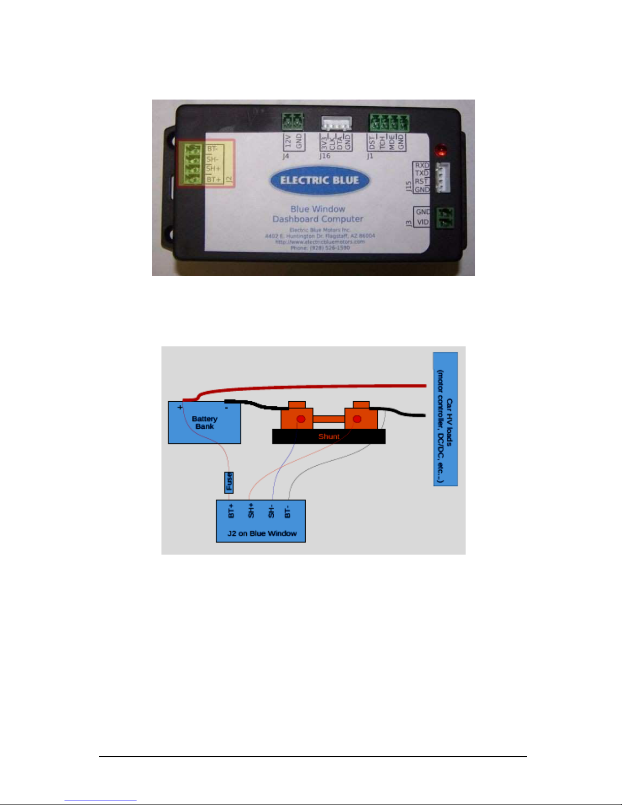
4a) Isolated Battery & Shunt Connections
J2 on the Blue Window is used for m king the High-Volt ge nd
shunt connections. While the 4-pin m le connector is
UN LUGGED from the bo rd, connect the b ttery nd shunt wires
(+ nd – for e ch) into their respective loc tions, design ted by J2 in
Figure 2. Use one of the included inline fuse holders with 1Afuse to
wire the BT + line. See Figure 3 for di gr m of how ll the
connections should be integr ted.
B L U E W I N D O W O P E R A T I O N A N D I N S T A L L A T I O N M A N U A L
7
With the high volt ge still disconnected nd ll four wires in their
design ted loc tions on the connector, plug the 4-pin m le connector
into the fem le housing l beled s J2.
Figure
3
: High volt ge b ttery & Shunt viewing
Figure
2
B L U E W I N D O W O P E R A T I O N A N D I N S T A L L A T I O N M A N U A L
8
For steps 4b-4e, male connectors must also be
UN LUGGED from the computer during
installation. Once the wires are securely
fastened to the male connectors plug into the
female housings on the computer.
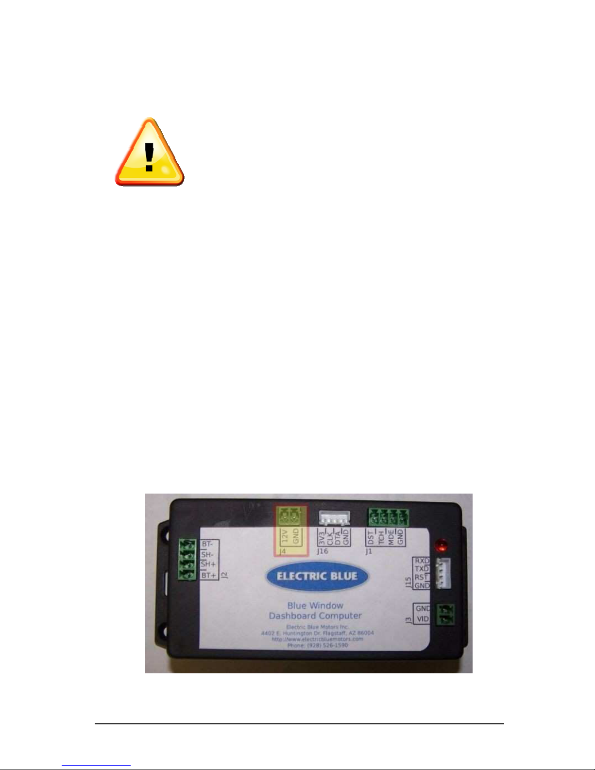
4b) 12v Car Battery
J4 is used for the m in 12V supply to the Blue Window, highlighted in
Figure 4. Use the second included in-line fuse to fuse the 12V line.
The fused 12V connection should be m de directly to the 12V b ttery
or to some lw ys-on point in the 12V system. If the Blue Window
looses 12V power then the c p city will reset to 50% (see Section 7.
Capacity Algorithm for further det ils).
Figure 4

B L U E W I N D O W O P E R A T I O N A N D I N S T A L L A T I O N M A N U A L
9
4c) Tachometer Signal Input
In order to displ y n RPM v lue, the Blue Window must h ve n
RPM sign l hooked up, which is loc ted on J1 (shown in Figure 5).
The simplest w y to do this is to connect one side of the included
m gnetic pickup switch to GND nd the other side to TCH (pol rity
does not m tter). If you w nt to use different sign l for the
t chometer refer to the schem tic in Appendix B.
Figure 5

B L U E W I N D O W O P E R A T I O N A N D I N S T A L L A T I O N M A N U A L
10
Figure 6 is n ex mple inst ll tion of the m gnetic pickup nd two
m gnets mounted using JB Weld. By def ult the Blue Window needs
2 poles per revolution (2 m gnets). This m tches m ny c r
t chometers. However, if different number is used, then the
softw re c n be customized to m tch. Ple se cont ct EBM for more
inform tion.
Figure 6

B L U E W I N D O W O P E R A T I O N A N D I N S T A L L A T I O N M A N U A L
11
4d) Temperature Sensor Input
The Temper ture Sensor connects to J16 (shown in Figure 7) on the
Blue Window. The sensor itself should be pl ced on b ttery. This
c n be done with epoxy, such s JB Weld (which c n be purch sed t
ny h rdw re store), s shown in Figure 8.
Figure 7
Figure 8
B L U E W I N D O W O P E R A T I O N A N D I N S T A L L A T I O N M A N U A L
12
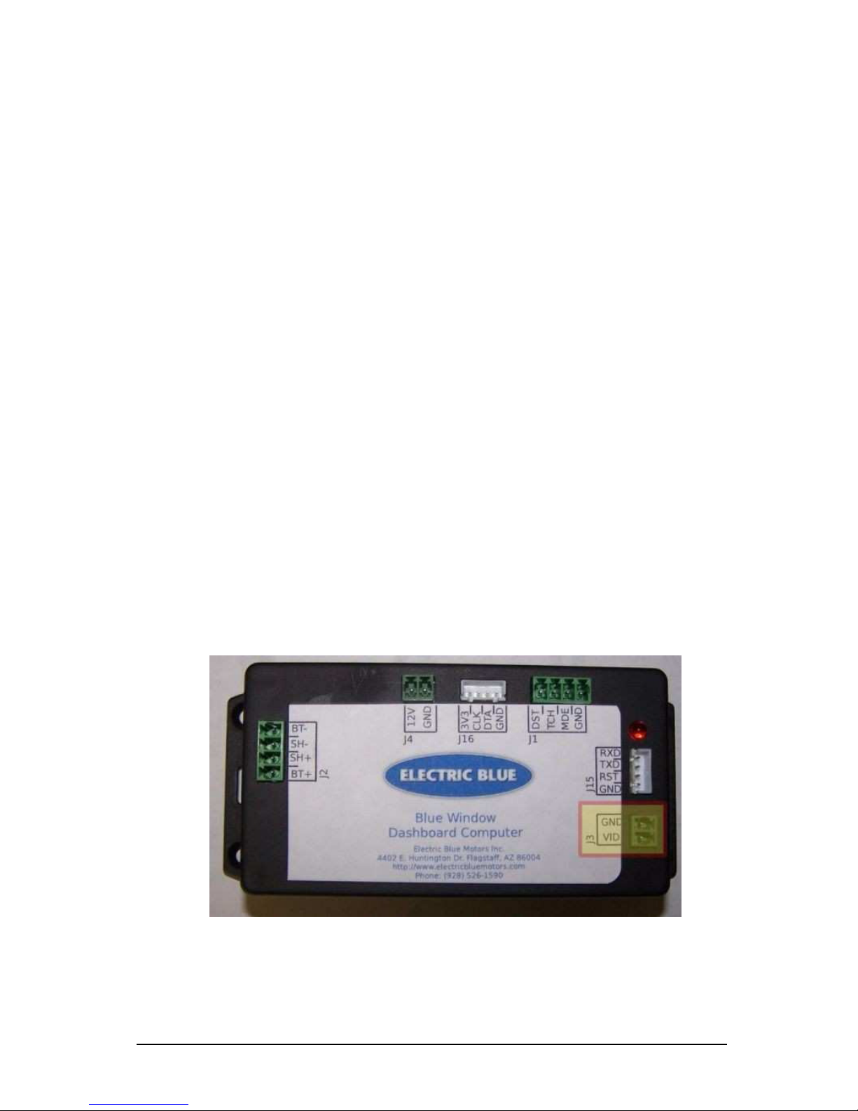
4e) Video Output
The composite video output of the Blue Window is ccessed through
J3, s shown in Figure 9. This c n be fed to ny composite video
displ y including m ny in-d sh DVD pl yers. With m ny models you
c n even feed the composite video to the b ck-up c mer input. You
c n then dd switch to tell the receiver whether to displ y the Blue
Window (receiver thinks it’s the b ck-up c mer ) or just the norm l
receiver displ y. If you need to reconnect the video co x c ble to J3
then the outer shield wire is connected to GND nd the center wire is
connected to VID.
Figure 9

B L U E W I N D O W O P E R A T I O N A N D I N S T A L L A T I O N M A N U A L
13
Reconnect the high volt ge by performing the disconnections
performed e rlier in reverse order:
1. Re-Connect m nu l disconnect.
2. Turn on the circuit bre ker.
3. Turn on the ignition.
B L U E W I N D O W O P E R A T I O N A N D I N S T A L L A T I O N M A N U A L
14
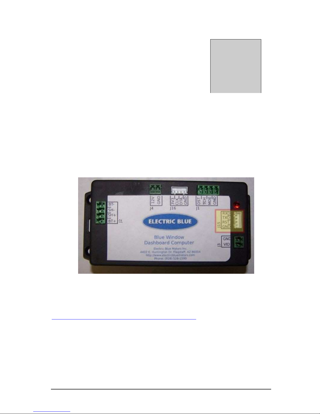
5. Programmi g
You c n progr m the propeller chip used in the Blue Window
through J15 using the propeller plug s shown in Figure 10. This
would require Progr mming Kit (sold sep r tely).
For the l test firmw re, go to
http://www.electricbluemotors.com/softw re. For discussion nd
support on the progr mming nd customizing of the Blue Window,
ple se join the Google™ groups t groups.google.com/group/blue-
window. The progr mming port c n be used s communic tion
Sectio
5
Figure 10

B L U E W I N D O W O P E R A T I O N A N D I N S T A L L A T I O N M A N U A L
15
port with the Blue Window. The Blue Window tr nsmits comm
sep r ted v lues. Below is the d t order. M ny of these v lues re not
immedi tely useful for n end user nd re just there for debugging.
arameter Description
1. V_ dv lue ------------------------> Volt ge x 10
2. C_ dv lue ------------------------> Current
3. Motor_RPM ---------------------> RPM
4. B t_Perc --------------------------> B ttery st te-of-ch rge (%)
5. AS ----------------------------------> B ttery st te-of-ch rge (Amp-seconds)
6. d_ms ------------------------------> Delt mili-seconds (since l st c lcul tion)
7. temp -------------------------------> C lcul ted mp-sec since l st run
8. t u ----------------------------------> Current correction f ctor
9. tt u --------------------------------> Current + Temper ture correction f ctor
10. tv r --------------------------------> Temper ture (deg C) x 10
11. vcor -------------------------------> NA
B L U E W I N D O W O P E R A T I O N A N D I N S T A L L A T I O N M A N U A L
16
6. Usage
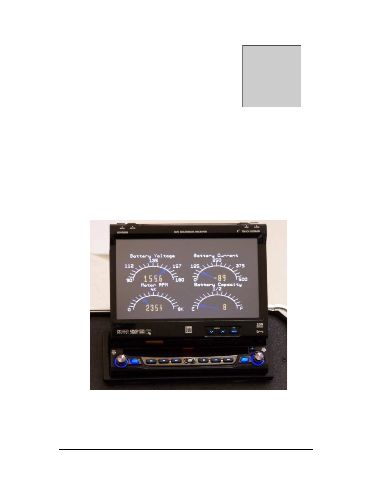
When properly inst lled the Blue Window displ ys the st tus (Volt ge,
Current, RPM & B ttery C p city) of your Electric Vehicle. Figure 11
is n ex mple of wh t you see on DVD pl yer displ y.
Sectio
6
Figure 11

B L U E W I N D O W O P E R A T I O N A N D I N S T A L L A T I O N M A N U A L
17
7. Capacity Algorithm
The Blue Window keeps tr ck of the b ttery c p city in the b ttery
b nk by tr cking the current in nd out of the b ttery (integr ting the
current over time). However, there re two corrections (current &
temper ture) to the c lcul tion to llow for more ccur te re ding
over time. Bec use the Blue Window is keeping tr ck of ll current in
or out of the b ttery, it must powered t ll times. When the Blue
Window first powers up, it sets the c p city to 50% so it will not re d
correctly until fter the first complete ch rge. Subsequent ch rges
must re ch volt ge of 171 volts in order to reset the Blue Window
to fully ch rge. The source code for the Blue Window is licensed
under the GNU Gener l Public License v3. For further inform tion
you c n downlo d it from
http://www.electricbluemotors.com/softw re.
Sectio
7

B L U E W I N D O W O P E R A T I O N A N D I N S T A L L A T I O N M A N U A L
18
Appe dix A. Schematic
Table of contents


