electrify home HomeStation EC2R040JPA10-00 User manual

Version: 2.0.1
Issue Dte: Mrch 10, 2021 /Dte de publiction : 10 mrs 2021
HomeStation
Level 2 Charger
INSTALLATION AND OPERATION MANUAL
HomeStation
Chargeur de niveau2
UIDE D'INSTALLATION ET D'UTILISATION

e l e c t r i f y h o m e .c a
Customer Support / Service l clientèle : 833-531-3226

Contents
Informtion 04
1Copriht 04
2About This Document 04
3Intended Use 04
4Chrer—Intended Use 04
5Importnt Sfet Instructions 04
6EMC Complince Sttement:
FCC Prt 15, Subprt B, Clss B
05
Product Overview 06
1Included Components List 07
2Recommended Tools 07
Instlltion Instructions 08
1Before Instllin 08
2Instlltion Steps 09
3Instlltion with Hrdwirin 10
Opertin Instructions 12
Chrer Sttus 14
1Sttus Indictor 14
2Indictor Definition 14
3Understndin Sttus
Indictor Ptterns
15
4Fults 15
Troubleshootin 16
Specifictions 17
Movin, Trnsporttion,
nd Store
18
Clenin 18
Wrrnt 18
Disposl 18
10
11

04 |HOMESTATION LEVEL 2 CHARGER
Information
Copriht
Copriht © 2021 Electrif Cnd LP. All rihts reserved. This document
is copriht protected. It m not be chned, reproduced, or distributed
without prior reement issued in writin b Electrif Cnd.
About This Document
These instructions describe how to operte nd cre for the chrer properl.
Additionl instructions re provided in the Electrif Cnd pp, nd we
recommend ou view the pp before usin the chrer. For our personl
sfet, follow the opertin instructions exctl. We recommend tht
certified electricin perform ll in-home instlltions, nd this chrer
should not be instlled in n circumstnces without first consultin with
n electricin fmilir with our home, its electricl pnel nd wirin.
Onl qulified, certified electricins should hrdwire this chrer.
Intended Use
These instructions ppl to the chrer nd its use in the USA nd Cnd.
Follow ll federl, provincil, nd locl lws, reultions, ordinnces, codes nd
sfet stndrds.
Chrer—Intended Use
1. This device is intended for indoor nd outdoor use. Do not obscure the lbel
on the chrer. All persons usin the chrer must first red nd understnd
these instructions.
2. This device is intended exclusivel for the chrin of electric vehicles fitted
with Tpe 1 plu (SAE J1772) nd chrin current control vi the pilot sinl
(IEC 61851-1). Do not use the chrer to chre or suppl other devices. Follow
ll federl, provincil, nd locl lws, reultions, ordinnces, nd sfet
stndrds rerdin use of this device.
Importnt Sfet Instructions
READ ALL THE INSTRUCTIONS BEFORE INSTALLIN, OPERATIN,
MAINTAININ, OR USIN THIS PRODUCT. SAVE THESE
INSTRUCTIONS. THE MUST BE PROVIDED TO EACH NEW OWNER.
DANER: RISK OF ELECTRICAL SHOCK.
INSTRUCTIONS PERTAININ TO A RISK OF FIRE OR ELECTRICAL SHOCK.
1. Do not use n dpters, converters, extension cords, or extension cbles
to increse the lenth of the chrin cble or power suppl cord.
2. Do not instll this chrer on FCI circuit breker.
3. Supervise children when device is in use. Children under 16 should not operte
this device. Also, smll prts re dnerous for children. Do not instll in the
presence of children.
4. Do not put finers into the electric vehicle connector.
5. Do not use this product if the power suppl cord or the electric vehicle cble
is fred, hs broken insultion, or shows n other sins of dme.
6. Do not use this product if the enclosure or the electric vehicle connector is
broken, crcked, open, or shows n other indiction of dme.
7. The mbient opertin temperture rne for this device is -22°F (-30°C)
to +122°F (+50°C). Do not operte the chrer outside this opertin rne.
8. To the full extent permitted b lw, Electrif Americ nd Electrif Cnd re
not responsible for phsicl injur, dme to propert or equipment cused
b the instlltion, use, repir, or mintennce of this product (not
pplicble in Quebec).
9. These opertin instructions describe theuse of the chrer in most commonl
used instlltion ndmountin scenrios.If situtions rise in whichitisnotpossible
toperformn opertion followin the procedures provided in this document,

INSTALLATION AND OPERATION MANUAL |05
Importnt Sfet Instructions (continued)
contct Electrif Americ or Electrif Cnd. Electrif Americ nd Electrif
Cnd re not responsible for n dmes tht m occur resultin from
custom instlltions or opertions tht re not described in this document.
10. Personl Protection Equipment: Use of proper personl protection equipment,
includin, but not limited to, ee protection, shock protection, loves, nd other
pproprite protection, is recommended when instllin or servicin n electricl
equipment. To reduce the risk of fire, onl connect this equipment to mximum
50 mperes overcurrent protection device in ccordnce with the Ntionl
Electricl Code, ANSI/NFPA nd the Cndin Electricl Code.
11. Do not use this equipment in n re with hzrdous or flmmble mterils
or vpors.
12. Arcin component in contctor: The chrer includes contctors tht, when
opened or closed, will cuse short durtion rc. The contctor is enclosed
in n pproprite electricl enclosure, but cution is required if this rc occurs in
the presence of flmmble vpors—s the vpors could inite, cretin n
explosion. Store hzrdous nd flmmble vpors nd mterils w from
ll electricl equipment. If hzrdous or flmmble sources re present, llow
sufficient time for ventiltion before opertin the chrer.
13. Do not open the chrer t n time durin instlltion or opertion!
Onl trined personnel should open the chrer.
14. Hndlin live components incorrectl m cuse rievous injuries or deth.
15. If the electricit service to the chrer is dmed, immeditel shut down
the power to the chrer b switchin off the circuit breker nd contct
licensed electricin.
16. Turn off circuit before remountin or replcin the chrer.
17. To reduce the risk of fire, connect onl to circuit provided with the proper
mximum brnch circuit overcurrent protection in ccordnce with the Ntionl
Electricl Code, the Cndin Electricl Code nd locl lws, reultions, codes,
nd stndrds.
18. Ensure tht ll components re dr throuhout the instlltion.
19. Product subject to modifiction without prior notice. This document miht not
contin the ltest chnes to the product’s specifictions or processes described
herein. For the most up-to-dte informtion, plese visit electrifyhome.ca.
EMC Complince Sttement:
IC, CAN ICES-002(B) / NMB-002(B)
IC ID: 26750-R040JPA1000
1. Cnd, Industr Cnd (IC) Notices This device complies with Cnd
licence-exempt RSS stndrd(s). Opertion is subject to the followin two
conditions: (1) this device m not cuse interference, nd (2) this device must
ccept n interference, includin interference tht m cuse undesired
opertion of the device.
2. Rdio Frequenc (RF) Exposure Informtion The rdited output power of the
Wireless Device is below the Industr Cnd (IC) rdio frequenc exposure limits.
The Wireless Device should be used in such mnner such tht the potentil for
humn contct durin norml opertion is minimized. This device hs lso been
evluted nd shown complint with the IC RF Exposure limits under mobile
exposure conditions. (ntenns re reter thn 20cm from person's bod).

06 |HOMESTATION LEVEL 2 CHARGER
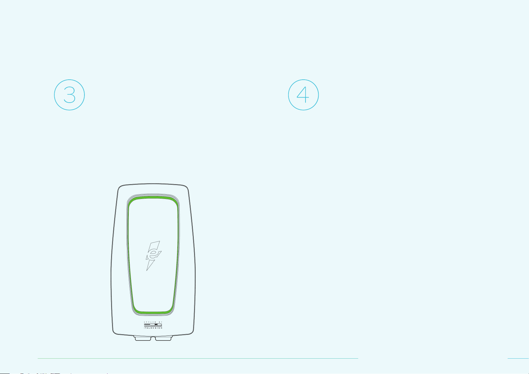
Product Overview
NO. ITEM NO. ITEM
1LED Rin 5Cble Holster
2Cosmetic Cover 6Vehicle Connector
3Plu 7Mountin Brcket
4Middle Cover 8 Bod

INSTALLATION AND OPERATION MANUAL |07
Included Components List Recommended Tools
TOOLS FOR PLU-IN INSTALLATION
1. Level
2. Pencil
3. Electric Drill
4.Phillips-Hed Screwdriver
TOOLS FOR HARDWIRED INSTALLATION
1. Level
2. Pencil
3. Electric Drill
4.Phillips-Hed Screwdriver
5. Dionl Cutter
6.Needle-Nose Pliers
7. Wire Stripper
8. Ferrule Crimpin Tool
Chrer
User mnul x 1
No. 8 wood screws x 4
(2 for brcket, 2 for holster)
Holster cse x 1
T20 Torx screw x 1
(for holster ssembl)
T30 Torx screws x 4
(for brcket ssembl)
Holster inlet x 1
T20 Torx bit x 1
T30 Torx bit x 1
Mountin brcket x 1 Mountin templte x 1

08 |HOMESTATION LEVEL 2 CHARGER
Installation Instructions
Before Instllin
We recommend tht certified electricin perform ll in-home instlltions,
nd this chrer should not be instlled in n circumstnces without first
consultin with n electricin fmilir with our home, its electricl pnel nd
wirin. Onl qulified, certified electricins should hrdwire this chrer.
These instructions describe how to operte nd cre for the chrer properl.
Additionl instructions re provided in the Electrif Cnd pp, nd we recom-
mend ou view the pp before usin the chrer. For our personl sfet, follow
the opertin instructions exctl.
Mke sure to follow ll locl codes nd reultions for sfet nd ccessibilit.
When considerin instlltion loctions, there re few thins to keep in mind:
DETERMINE OUR POWER RATIN
1. Prior to instllin our chrer, work with our electricin to determine the
mpere settin tht best fits our home’s electricl cpcit. This m
determine which tpe of instlltion ou will need nd the best loction for
the chrer.
PICK OUR LOCATION
1. Instll the mountin brcket for the chrer—mesured from the bottom of the
brcket between 31.5 (80 cm) nd 47.2" (120 cm) bove the round.
Confiurtion Instlltion Tpe
16A Hrdwire Onl
32A Plu-In or Hrdwire
40A Plu-In or Hrdwire
1. Instll the holster—mesured from the
bottom between 31.5" (80 cm) nd
43.3" (110 cm) bove the round.
2. To llow for proper irflow nd workin room, the chrer should be locted
12" (30.5 cm) from n other equipment, wlls, or other obstructions.
3. The brcket must be mounted on flt surfce so tht it does not deform
when properl secured.
4. Plu-In Instlltion Note: Prior to mountin the chrer, turn off the circuit
breker for the desired outlet nd plu in the chrer. This will llow for
proper plcement of the chrer.
5. When selectin loction to instll the chrer, mke sure tht the chre
cble cn esil connect to the vehicle when it is prked. Keep in mind where
the vehicle’s chrin port is locted (it vries from vehicle to vehicle) nd
how the vehicle will usull be prked.
6. The best instlltion loctions hve enouh spce to esil store the cble
round the chrer itself (or the holster provided with the chrer), nd will not
interfere with pthws or other items in the re or drivew.
TIP: Be sure the power cord hs
entle curve but is not stretched.

INSTALLATION AND OPERATION MANUAL |09
Instlltion Steps
This product must hve proper electricl round connection. Proper electricl
roundin reduces the risk of electric shock. This product is equipped with
power suppl cble tht includes n equipment roundin conductor. The power
suppl cble must be plued into comptible outlet tht is properl instlled
nd rounded in ccordnce with ll locl codes nd ordinnces.
WARNIN: Improper connection of the power suppl cble cn result in
risk of electric shock. Check with qulified electricin to ensure the
product is properl rounded. Do not modif the power suppl cble provided
with the product. Ensure the proper outlet is instlled b licensed nd
qulified electricin.
INSTALL THE MOUNTIN BRACKET AND CHARER
1. The product is sttionr piece of equipment tht is desined to be
mounted on wll. The mountin templte, included with the product, shows
the proper loction to drill pilot holes for the mountin brcket screws.
2. Usin level, plce the mountin templte in the loction where ou would
like to mount the chrer.
3. Tpe the templte in plce nd mesure the heiht to ensure the chrer is
between 31.5" (80 cm) nd 47.2" (120 cm) bove the round.
NOTE: The brcket must be mounted on flt surfce so tht the brcket
does not deform when properl secured.
4. Instll the mountin brcket securel to the wll,
linin the holes in the brcket with those mrked
on the wll, nd secure the mountin brcket usin
the provided screws or other fsteners tht best
suit our specific instlltion needs.
5. Once the mountin brcket is instlled, plce the chrer into the brcket
nd secure the chrer to the brcket usin the 4 supplied T30 Torx screws.
INSTALL THE HOLSTER
The cble holster is optionl. Instll the holster—mesured from the bottom
between 31.5" (80 cm) nd 43.3" (110 cm) bove the round. Plese select
the proper mountin hrdwre for our prticulr instlltion.
PLU-IN INSTALLATION USIN THE ATTACHED SUPPL POWER PLU
Insert the power plu into the power outlet (NEMA 14-50 receptcle).
AMPERAE CONFIURATION WITH THE ELECTRIF CANADA APP
1. Downlod nd instll the Electrif Cnd pp on our smrtphone
(vilble for iOS nd Android).
2. Ensure tht our phone’s Wi-Fi is turned on. It is not required to be
connected to network.
3. Follow the instructions in the pp to connect to our chrer nd confiure
our mpere settin.

10 |HOMESTATION LEVEL 2 CHARGER
Instlltion with Hrdwirin
These instlltion instructions re intended for certified electricins. Onl
qulified, certified electricins should hrdwire the chrer. In ddition
to the chrer instlltion instructions, follow ll federl, provincil, nd locl
lws, reultions, ordinnces, codes, nd sfet stndrds.
This product must be properl rounded—either to rounded, metl,
permnent wirin sstem or n equipment-roundin conductor run with
the suppl power circuit conductors nd connected to the roundin
terminl on the product.
CAUTION: To reduce the risk of fire, connect onl to circuit provided with 50
mperes mximum brnch circuit overcurrent protection in ccordnce with
the Ntionl Electricl Code, ANSI/NFPA 70, nd the Cndin Electricl Code,
Prt 1, C22.1.
REMOVE THE COSMETIC AND MIDDLE COVERS
1. Remove the screw locted t the bottom of cosmetic cover b usin the
T20 Torx bit.
2. Tilt the cosmetic cover upwrd nd seprte it from the middle cover.
3. Remove the screws usin the T20 Torx bit.
4. Plce the middle cover on the bod of the chrer b hnin the two hooks
on the bck of the middle cover to the ledes t the bottom of the bod.
5. Once the cover hs been removed, open the cble mnement clip on
the riht-hnd side of the enclosure to relese the LED cble ttched to the
cover. This will llow the cover to be hun on the bottom of the enclosure.
REMOVE THE PLU CABLE
1. Remove the plu cble b loosenin the 3 center screws (shown s L1, L2, nd
PE) in the terminl block. Do not loosen the screws securin the terminl block
to the bod.
2. This product hs two mens of strin relief: metl brcket on the interior
of the bod nd blck nut on the outside of the bod.
3. Loosen the left strin relief nut on the outside of the bod.
4. Remove the left strin relief strp from the inside of the bod.
5. Pull the cble down throuh the cble lnd nd remove the strin
relief nut from the plu cble.
FLIP THE COSMETIC COVER UPWARD TO SEPARATE IT FROM THE BOD
1. Insert the new cble throuh the cble lnd nut, then into the bod
of the chrer.
NOTE: The conductor size m be no less thn 6 AW.
Durin instlltion, be sure to use proper personl protective equipment
nd do not touch wirin terminls with our finers.
NOTE: The circuit breker must be rted for 125% of the chosen
opertin current.

INSTALLATION AND OPERATION MANUAL |11
2. Crimp insulted wire ferrules onto ech suppl power wire, includin round.
Follow the ferrule mnufcturer’s instructions for crimpin the ferrules onto
ech wire.
3. Insert ech ferrule terminl wire in the terminl block, ensurin the wires re
locted properl.
4. Tihten terminl block screws to 33–40 in-lb (3.73-4.5 N-M) of torque.
5. Reinstll nd tihten the strin relief strp, ensurin the wires re
not strined between the strin relief strp nd the terminl block.
6. Tihten the strin relief nut to the cble lnd.
MANUAL AMPERAE CONFIURATION (OPTIONAL)
Use this method onl if required b locl code; otherwise, use the Electrif
Cnd pp to set the mpere confiurtion.
1. The mpere of the chrer cn be mnull set b confiurin the DIP
switches s shown t riht. It is lws preferble to confiure the mpere
vi the Electrif Cnd pp.
NOTE: When there is difference between the DIP switch settins nd the
settin in the Electrif Cnd pp, the chrer will issue chre t the
lowest mpere settin.
REATTACH THE COVER
1. Secure the middle cover with the screws removed (s in the previous steps).
2. Attch the cosmetic cover b plcin the top ede of the cosmetic cover over
the middle cover nd entl pushin the cosmetic cover into plce. Loosen the
left strin relief nut on the outside of the bod. Secure the cover with the T20
Torx screws.
AMPERAE CONFIURATION WITH THE ELECTRIF CANADA APP
1. Downlod nd instll the Electrif Cnd pp on our smrtphone (vilble
for iOS nd Android).
2. Ensure tht our phone’s Wi-Fi is turned on. It is not required to be connected to
network.
3. Follow the instructions in the pp to connect to our chrer nd confiure
our mpere settin.
WI-FI SETUP (PLU-IN OR HARDWIRED INSTALLATION)
1. To connect the chrer to Wi-Fi network, downlod nd instll the Electrif
Cnd pp on our smrtphone (vilble for iOS nd Android).
2. Follow the instructions in the pp to set up with Wi-Fi connection.

12 |HOMESTATION LEVEL 2 CHARGER
Insert the vehicle connector into the charging
port on your electric vehicle. The charger will
light up green when a connection is detected.
Once the charger is plugged into the vehicle, the
charger will begin flashing blue as it links with
the vehicle. When the charger is flashing solid blue,
the vehicle is charging.
Operating Instructions
The charger light will dim on the front and remain
blue on the bottom for the entire charging session.
INSTALLATION AND OPERATION MANUAL |13
Charging is complete when the charger turns
green once more.
Press the thumb lever on the vehicle connector
to disconnect from the vehicle.
14 |HOMESTATION LEVEL 2 CHARGER
Charger Status
If ou re experiencin difficult chrin, fult indictor liht, or n other
issue usin the chrer, plese see the Troubleshootin section for ssistnce.
If the issue persists, plese contct Electrif Cnd Customer Support t
833-531-3226.
Sttus Indictor
The chrer is equipped with n interted LED rin to llow for cler
communiction of the chrer’s sttus. For ener efficienc, onl the
bottom section of the LED rin will remin illuminted (for pproximtel
two minutes) since the lst user interction.
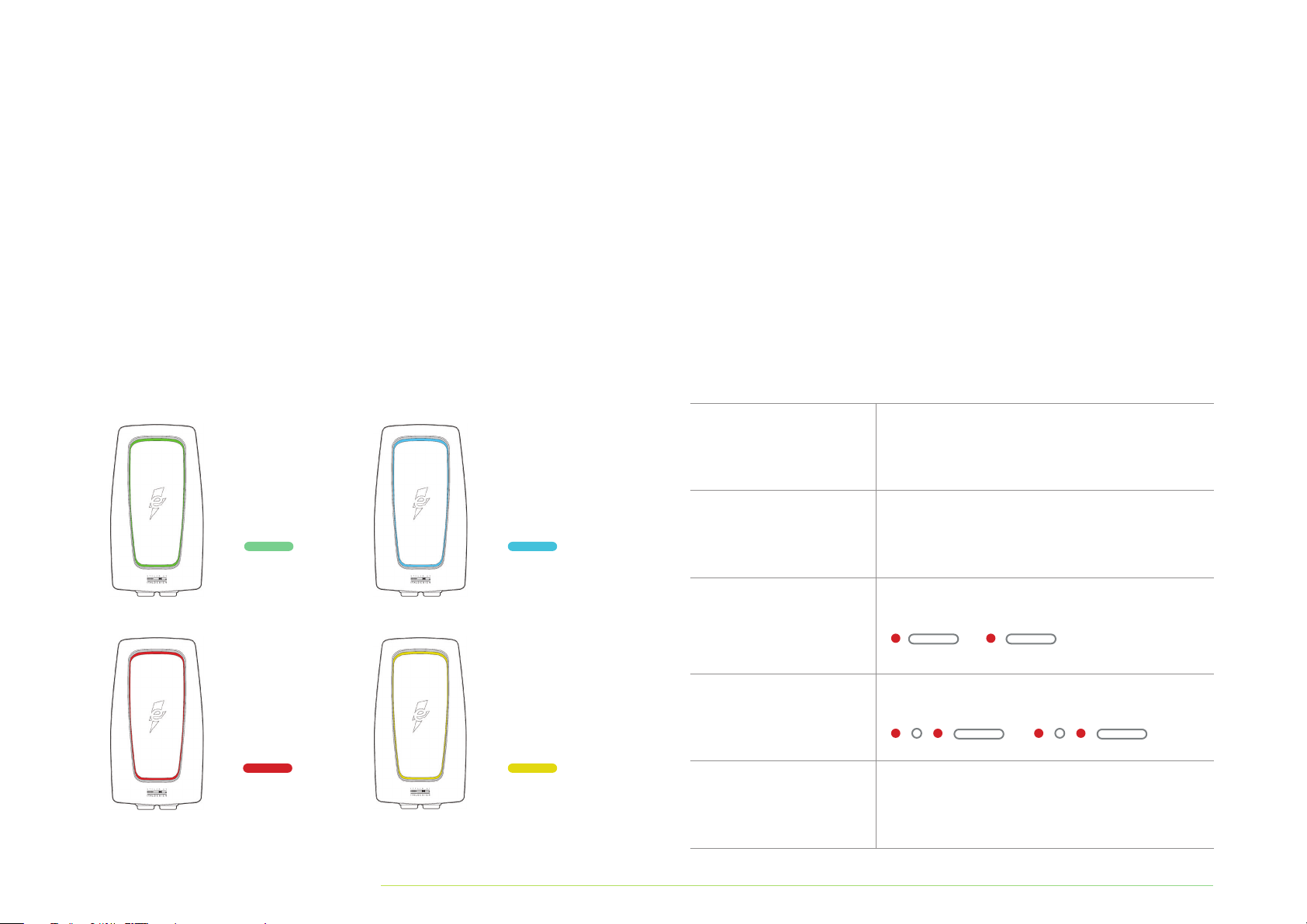
Indictor Definition
LED PATTERN DEFINITION
Slow flshin 2 seconds between flshes.
Fst flshin Less thn 1 second between flshes.
1 flsh
1 second on, 5 seconds off.
2 flshes
1 second on, 1 second off; 1 second on, 5 seconds off.
3+ flshes Follows the sme flshin pttern s
directl bove.
REEN
Stndb
BLUE
Chrin
RED
Fult
ELLOW
Wi-Fi Setup

INSTALLATION AND OPERATION MANUAL |15
Understndin Sttus Indictor Ptterns
LED COLOR INDICATOR DESCRIPTION
No color Power off.
Blue & reen,
lterntin nd fst flshin Initil nd self-test.
reen, solid Stndb.
Blue, fst flshin EV connected.
Blue, slow flshin Preprin to chre.
Blue, solid Chrin.
reen, slow flshin Chrin finished or stopped b user.
ellow, solid First successful connection to Wi-Fi.
Red, constnt nd/or flshin Fult indictor.
See the Troubleshootin section.
Fults
LED INDICATOR DESCRIPTION
Red, 1 flsh Hih or low input volte detected.
Red, 2 flshes round fult detected.
Red, 3 flshes round connection error.
Red, 4 flshes Hih input current detected.
Red, 5 flshes Opertin temperture limit exceeded.
Disconnect the unit from power.
Red, 6 flshes Instlltion error.
Line nd neutrl re swpped.
Red, 7 flshes Vehicle communiction error.
Red, solid Self-test error or enerl error. Disconnect the
chrer from power source nd reconnect it
fter 10 seconds to power ccle the chrer.

16 |HOMESTATION LEVEL 2 CHARGER
Troubleshooting
SITUATION CAUSE ACTION
Sttus indictor does
not illuminte. Chrer is not receivin power.
Ask certified electricin to check tht the power input is connected correctl
nd the power is within opertin rne of the unit.
Disconnect the chrer from power source nd reconnect fter 10 seconds to power
ccle the chrer.
If the problem persists, contct Customer Support t 833-531-3226.
Indictor does not flsh blue fter
pluin in the vehicle connector.
Vehicle btter is full chred.
Plu is not properl connected.
Check if the EV btter is fulll chred.
Check if the vehicle connector is full inserted to the EV.
If the problem persists, contct Customer Support t 833-531-3226.
Indictor strts to flsh red
while chrin.
Chrer hs detected n error.
Chrer hs encountered fult.
Wit until the temporr error is resolved nd the chrer returns to norml condition,
tpicll less thn 10 seconds.
Disconnect the chrer from the vehicle, wit for the error to cler, nd reconnect the
chrer to the vehicle.
If the error persists, disconnect the chrer from power source nd reconnect fter
10 seconds to power ccle the chrer.
If the error is not resolved, contct Customer Support t 833-531-3226.
Indictor illumintes red. Chrer hs detected fult.
Disconnect the chrer from the vehicle, wit for the error to cler, nd reconnect
the chrer to the vehicle.
If the error persists, disconnect the chrer from power source nd reconnect fter
10 seconds to power ccle the chrer.
If the error is not resolved, contct Customer Support t 833-531-3226.

INSTALLATION AND OPERATION MANUAL |17
Specifications
Model EC2R040JPA10-00
Mesurements (H x W x D) 15.75" x 8.66" x 6.75" (pprox.)
Cble Lenth 24 Feet
Instlltion Tpe Fixed Wll Mounted
Weiht 19.85 lbs. (pprox.)
Enclosure Rtin NEMA Tpe 3R
Input Power 208V-240V AC Split Phse
(3-Wire – L1, L2, round)
AC Plu-In Cord NEMA 14-50
Mx. Current Rtin 40 Amps
Output Power Up to 9.6kW (240V AC @ 40A)
Power Meterin Accurc +/- 1% t Full Scle
Chre Connector SAE J1772
Chrin Protocol SAE J1772
User Interfce/HMI LED Liht Rin
Wireless WLAN with 2.4Hz b//n with WPA2
Communiction Protocol CPP 1.6+ JSON Complint
AC Fult Monitor FCI Interted (20mA CCID for AC)
Short Circuit/
Overlod Protection
50A Circuit Breker (not provided with
unit, no FCI) for 40 A Output (Refer to
locl codes for proper breker sizin.)
Vehicle Communiction Pilot Sinl (IEC 61851-1:2017)
Certifictions
CSA C22.2 No. 280-16, CSA C22.2
No. 281.1, CSA C22.2 No. 281.2, ICES
002(B)
Opertin Temperture
-22°F to +122°F (-30°C to +50°C)
Full Lod Therml Overlod
Protection: Output power reduced
t hiher tempertures.
Store Temperture -40°F to +176°F (-40°C to +80°C)
Humidit 5%—95% (Non-Condensin)

18 |HOMESTATION LEVEL 2 CHARGER
Moving, Transportation,
and Storage
WARNIN: Improper movin or store of this device m result in
risk of fire or electric shock.
Do not lift or crr the chrer b the cords. Do not llow the connector
cble to dr or touch the round when movin the chrer. This device
should be stored in dr loction tht’s between -40°F nd +176°F.
Cleaning
The chrer m onl be clened with wter; the use of lukewrm wter
is recommended. Do not use clenin ents continin solvents. Dr the
chrer with clen pper towel or soft cloth prior to use.
Do not use this product if the power cord or the electric vehicle cble is fred,
hs broken insultion, or shows n other sins of dme. Do not use this
productif the enclosure or the electric vehicle connector is broken, crcked,
open, or shows n other indiction of dme.
For further ssistnce, contct us t 833-531-3226.
Warranty
Customer Support cn provide more informtion on the terms of the
wrrnt. However, the followin cses re not covered b the wrrnt:
A. Defects or dme cused b n filure to instll, operte, or cre for
this product s specified in this Instlltion nd Opertion Mnul nd
the Electrif Cnd pp.
B. Costs nd dme cused b repir work which hs not been mde
b n Electrif Cnd–pproved uthorized specilist or electricin.
Disposal
The chrer is n electricl device. Follow ll federl, provincil, nd
locl lws, reultions, ordinnces, nd sfet stndrds rerdin
disposl of this device.

Table des matières
Informtion 20
1Droit d’uteur 20
2À propos de ce document 20
3Utilistion prévue 20
4Chreur—Utilistion prévue 20
5Instructions de sécuritéimportntes 20
6Déclrtion de conformité
électromnétique :
prtie15 des rèles de l FCC,
sous-prtie B, clsse B
21
Aperçu du produit 22
1Liste des composnts inclus 23
2Outils recommndés 23
Instructions d’instlltion 24
1Avnt l’instlltion 24
2Étpes d’instlltion 25
3Instlltion cblée 26
Instructions d’utilistion 28
Étt du chreur 30
1Vont d’étt 30
2Définition du vont 30
3Compréhension des
schéms du vont d’étt
31
4Anomlies 31
Dépnne 32
Spécifictions 33
Déménement,
trnsport et entrepose
34
Nettoe 34
rntie 34
Mise u rebut 34
10
11

20 |BORNE DOMESTIQUE CHARGEUR DE NIVEAU 2
Information
Droit d’uteur
Droit d’uteur © Electrif Cnd LP, 2021. Tous droits réservés. Ce document
est protéé pr le droit d’uteur. Il est interdit de le modifier, de
le copier ou de le distribuer sns l’utoristion écrite d’Electrif Cnd.
À propos de ce document
Ces instructions décrivent l fçon d’utiliser correctement le chreur et d’en
prendre soin. Des instructions supplémentires sont fournies dns l’ppliction
Electrif Cnd, et nous vous recommndons de consulter l’ppliction
vnt d’utiliser le chreur. Pour votre sécurité personnelle, suivez exctement
les instructions d’utilistion. Nous recommndons qu’un électricien certifié
effectue toutes les instlltions domicile, et ce chreur ne doit en ucun
cs être instllé sns consulter u prélble un électricien connissnt bien
votre mison, son pnneu électrique et son cble. Seuls des électriciens
qulifiés et certifiés doivent effectuer le cble du chreur.
Utilistion prévue
Ces instructions s’ppliquent u chreur et son utilistion ux Étts-Unis.
Respecter l’ensemble des lois, rèlements, ordonnnces, codes et normes de
sécurité fédérux, éttiques et locux.
Chreur – Utilistion prévue
1. Cet ppreil est destiné une utilistion l’intérieur et l’extérieur. Ne
msquez ps l’étiquette sur le chreur. Toute personne utilisnt le chreur
doit d’bord lire et comprendre ces instructions.
2. Cet ppreil est destiné exclusivement l rechre de véhicules électriques
équipés d’une prise de tpe 1 (SAE J1772) et u contrôle du cournt de chre
vi le sinl pilote (IEC 61851-1). N’utilisez ps le chreur pour rechrer ou
limenter d’utres ppreils. Respectez l’ensemble des lois, rèlements,
ordonnnces et normes de sécurité fédérux, provinciux et locux reltifs
l’utilistion de cet ppreil.
Instructions de sécurité importntes
LISEZTOUTES LESINSTRUCTIONSAVANTL’INSTALLATION, L’UTILISATION OU
L’ENTRETIEN DECE PRODUIT. CONSERVEZ LES PRÉSENTES INSTRUCTIONS. ELLES
DOIVENT ÊTRE REMISES À CHAQUE NOUVEAU PROPRIÉTAIRE.
DANER : RISQUE DE CHOC ÉLECTRIQUE.
LESINSTRUCTIONSENCAS DERISQUED’INCENDIEOUDECHOCÉLECTRIQUE
1. N’utiliser ucun dptteur, convertisseur ou cble de prolonement ni
ucune rllone pour umenter l lonueur du cble de rechre ou du
cordon d’limenttion.
2. Ne ps instller ce chreur sur un disjoncteur DDFT.
3. Surveiller les enfnts lorsque l’ppreil est utilisé. Les enfnts és de moins de 16
ns ne doivent ps utiliser cet ppreil. De plus, les petites pièces sont dnereuses
pour les enfnts. Ne ps effectuer l’instlltion en présence d’enfnts.
4. Ne ps insérer les doits dns le connecteur du véhicule électrique.
5. Ne ps utiliser ce produit si le cordon d’limenttion ou le cble du véhicule
électrique est effiloché, si son isoltion est brisée ou s’il présente tout utre
sine de domme.
6. Ne ps utiliser ce produit si le boîtier ou le connecteur du véhicule électrique est
cssé ou ouvert, ou s’il présente tout utre sine de domme.
7. L ple de tempérture mbinte de fonctionnement de cet ppreil est de
-30 °C (-22°F) +50 °C (+122 °F). Ne ps utiliser le chreur l’extérieur de
cette ple de fonctionnement.
8. Dns toute l mesure permise pr l loi, Electrif Americ et Electrif Cnd ne
sont ps responsbles des blessures et des dommes mtériels cusés pr
l’instlltion, l’utilistion, l réprtion ou l’entretien de ce produit (ne s’pplique
ps u Québec).
9. Les présentes instructions d’utilistion décrivent l’utilistion du chreur dns les
situtions d’instlltion et de monte les plus courntes. Dns l’éventulité où il
est impossible d’effectuer une opértion conformément ux procédures décrites
dns le présent document, communiquez vec Electrif Americ ou Electrif
Cnd. Electrif Americ et Electrif Cnd ne sont ps responsbles des
Table of contents
Languages:
Popular Batteries Charger manuals by other brands

Hitachi
Hitachi UC 10SFL Safety instructions and instruction manual

Shimano
Shimano Ultegra SM-BCR1 user manual

MZ electronic
MZ electronic MZBC_2460 Instructions for use

Eddie Bauer
Eddie Bauer clim8 Instruction guide

STRIKEMASTER
STRIKEMASTER LITHIUM 24V BATTERY CHARGING BASE quick start guide

Worx
Worx WA3739 manual


