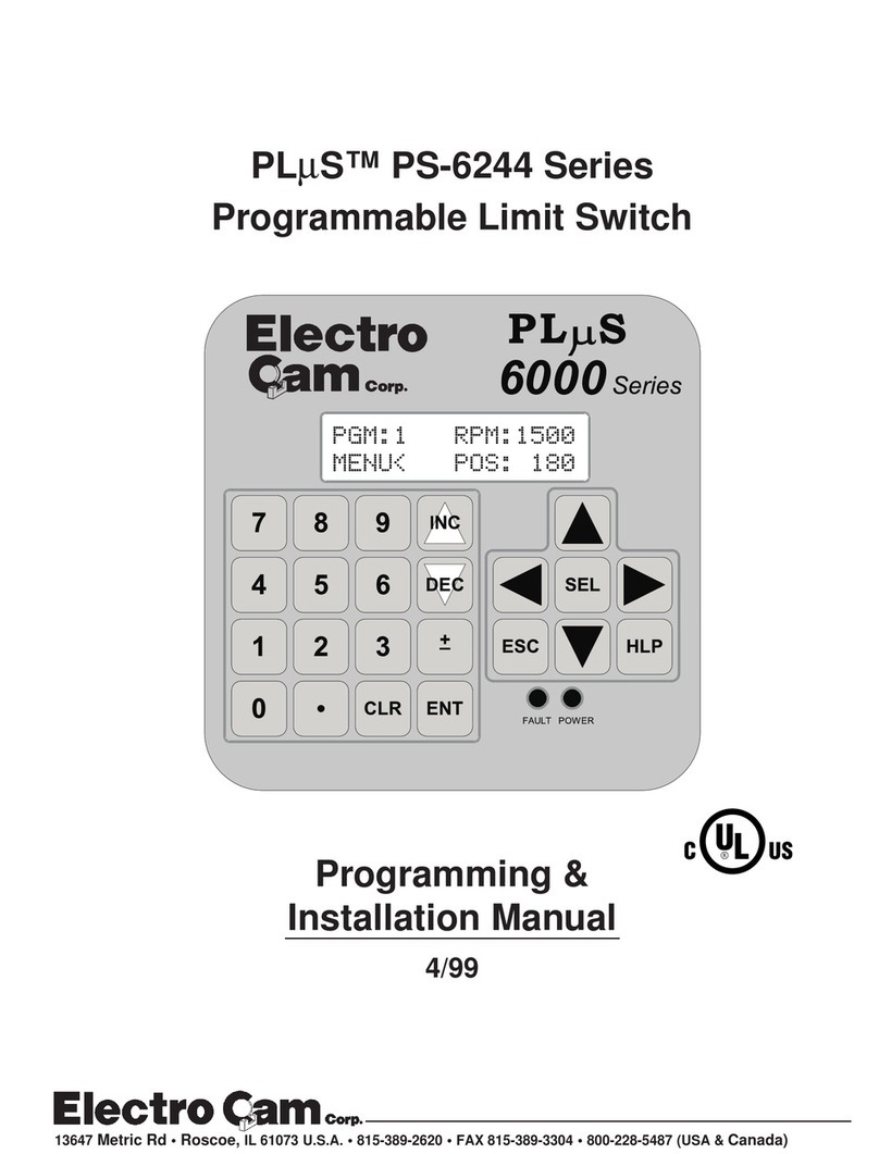
Electro Cam Plus PS-6144 Series User manual

PLµS®PS-6144 Series
Programmable Limit Switch
6000
Series
Programming &
Installation Manual
13647 Metric Rd • Roscoe, IL 61073 USA • 815/389-2620 • FAX 815/389-3304 • 800-228-5487 (U.S.A. and Canada)

Copyright © 2001
All Rights Reserved
Neither this document nor any part may be reproduced or transmitted in
any form or by any means without permission in writing from the publisher.
®,PLµS®,SLIMLINE®, and PLµSNET®are all registered trademarks of


Table of Contents
Pulse Copy................................. 3-22
Rate Setup................................. 3-24
Resolver Type ............................ 3-25
RPM Update Rate...................... 3-25
Scale Factor............................... 3-25
Setpoint Use .............................. 3-26
Setpoints.................................... 3-26
Shaft Position............................. 3-28
Software Version........................ 3-28
Speed Compensation ................ 3-28
Speed Comp Mode.................... 3-29
Timed Outputs ........................... 3-30
Toggle RPM ............................... 3-30
Section 4—Speed Compensation
Introduction..................................... 4-1
Examples........................................ 4-2
Leading/Trailing Speed Comp......... 4-4
Negative Speed Comp.................... 4-6
Programming Guidelines ................ 4-6
Section 5—Output Grouping & Modes
Introduction..................................... 5-1
Mode 0............................................ 5-3
Mode 1............................................ 5-3
Mode 2............................................ 5-4
Mode 3............................................ 5-5
Mode 4............................................ 5-6
Mode 5............................................ 5-7
Speed Comp & Modes ................... 5-8
Section 6—Communications
PLuSNET II Program .................... 6-1
Serial Communications Using
Electro Cam Corp. Protocol ............ 6-3
Error Codes .................................... 6-12
Checksum Calculations .................. 6-12
Serial Communications Using
Modbus ASCII Protocol .................. 6-13
Section 7—Troubleshooting
Controller Diagnostics..................... 7-1
Keypad Diagnostics ........................ 7-2
Resolver Troubleshooting ............... 7-3
General Troubleshooting................. 7-4
Fuse Part Numbers ........................ 7-6
Appendix
Controller Specifications................. A-1
Slimline Module Specifications ....... A-2
Transistor Output Specifications ..... A-3
Resolver Specifications .................. A-3
Factory Defaults.............................. A-3
PS-6144 Setpoint Record............... A-4
Index
Section 1—Introduction
Mechanical Cam Switches.............. 1-1
Programmable Limit Switches ........ 1-1
PS-6144 Description....................... 1-2
Basic Terminology........................... 1-3
PS-6144 Standard Features ........... 1-3
PS-6144 Optional Features ............ 1-4
Section 2—Installation & Wiring
General Mounting & Wiring............. 2-1
Mounting Dimensions ..................... 2-2
Terminals & Components
PS-6144-24M17......................... 2-3
PS-6144-24-X16-M09................ 2-4
Controller Input Wiring .................... 2-5
Output Wiring.................................. 2-8
Keypad Wiring................................. 2-12
DIP Switch Configurations.............. 2-13
Communications Wiring.................. 2-15
Resolver Installation ....................... 2-16
Resolver Dimensions...................... 2-17
Resolver Cables ............................. 2-18
Fuse Tester & Fuse Replacement... 2-19
Output Transistor Replacement ...... 2-20
Section 3—Programming
Keypad Overview............................ 3-1
Menu Tree ...................................... 3-2
Initial Programming......................... 3-3
Functions (Alphabetically)
Analog Output............................ 3-4
Analog Quantity ......................... 3-5
Channel Copy ............................ 3-6
Communications ........................ 3-6
Default Program......................... 3-7
Enable Codes ............................ 3-8
Enable Options .......................... 3-10
Group Position Display............... 3-10
Increasing Direction ................... 3-11
Input Status................................ 3-12
Keyboard Quantity ..................... 3-12
Main Screen............................... 3-13
Memory Tests............................. 3-14
Motion ANDing........................... 3-14
Motion Detection........................ 3-15
Offset ......................................... 3-16
Output Enable ANDing............... 3-18
Output Groups ........................... 3-18
Output Status............................. 3-19
Password ................................... 3-20
Per Channel Enable................... 3-21
Program Copy............................ 3-21
Program Select Mode ................ 3-22

WARRANTY
1. Electro Cam Corp. warrants that for a period of twelve (12) months from the date of shipment to
the original purchaser, its new product to be free from defects in material and workmanship and
that the product conforms to applicable drawings and specifications approved by the Manufacturer.
This warranty period will be extended on Distributor or OEM orders to a maximum of eighteen
months to take into consideration Distributor or OEM shelf time.
2. The remedy obligations of Electro Cam Corp. under this warranty are exclusive and are limited
to the repair, or at its option, the replacement or refund of the original purchase price of any new
apparatus which proves defective or not in conformity with the drawings and specifications. Ship-
ment of the claimed defective product to Electro Cam Corp. shall be at the cost of the consumer.
Shipment of the repaired or replacement product to the consumer shall be at the cost of Electro
Cam Corp. All claims must be made in writing to Electro Cam Corp., 13647 Metric Road, Roscoe,
IL 61073 USA.
3. In no event, and under no circumstances, shall Electro Cam Corp. be liable for:
a. Any product damaged or lost in shipment. Inspection for damage should be made before
acceptance or signing any delivery documents releasing responsibility of the delivering carrier.
b. Product failure or damages due to misuse abuse, improper installation or abnormal conditions
of temperature, dirt or other contaminants as determined at the sole discretion of Electro Cam
Corp.
c. Product failures due to operation, intentional or otherwise, above rated capacities as deter-
mined at the sole discretion of Electro Cam Corp.
d. Non-authorized expenses for removal, inspection, transportation, repair or rework. Nor shall
the manufacturer ever be liable for consequential and incidental damages, or in any amount
greater than the purchase price of the equipment.
4. There are no warranties which extend beyond the description on the face hereof. This warranty
is in LIEU OF ALL OTHER WARRANTIES, EXPRESSED OR IMPLIED INCLUDING (BUT NOT
LIMITED TO) ANY IMPLIED WARRANTIES OF MERCHANTABILITY OR FITNESS FOR A PAR-
TICULAR PURPOSE, ALL OF WHICH ARE EXPRESSLY DISCLAIMED. Any legal proceeding
arising out of the sale or use of this apparatus must be commenced within (18) months of the
date of shipment from the manufacturer.

1-1 Introduction
Mechanical Cam Switches
Mechanical Cams The PS-6144 Programmable Limit Switch electronically simulates mechanical cam
switches. A cam switch consists of a roller limit switch whose arm rides on a cam as
shown in Figure 1. The cam shaft is driven by a machine at a 1:1 ratio, so that the cam
switch turns on and off at specic positions in the machine cycle. Cam limit switches
have the following disadvantages:
• The roller, the cam, and the limit switch wear out.
• The machine must be stopped during adjustment.
• On/off patterns are limited, and changing the pattern may require replacement of one
cam with another. For example, a cam that switches on and off twice in one revolution
would need to be replaced with a different cam if three on/off pulses per revolution
were required.
• They cannot run at high speeds because of contact bounce and excessive mechanical
wear.
Figure 1—Basic Cam Switch
Programmable Limit Switches
PS-6144ʼs & Resolvers The PS-6144 Programmable Limit Switch uses a resolver (see Figure 2 on page 2)
instead of a cam to indicate machine position. A resolver uses xed and rotating coils
of wire to generate an electronic signal that represents shaft position. The resolver is
usually coupled to a machine shaft at a 1:1 ratio so that one resolver shaft rotation cor-
responds to one machine cycle. Resolvers have no brushes, contacts, or any frictional
moving parts to wear out.
Based on the resolver signal, the PS-6144 Programmable Limit Switch turns electrical
circuits, or “Outputs,” on and off, simulating the mechanical roller limit switch. Because
the combination PS-6144/resolver system is completely electronic and has no frictional
parts, it offers several advantages over mechanical cam switches:
• Long service life with no parts to wear out.
• “On” and “off” points can be adjusted instantly from the keypad; there are no cams to
rotate or replace.
• Adjustment is possible with the machine running or stopped.
• Programmable logic allows complex switching functions that are impossible with
mechanical cams.
• Operation at speeds up to 3000 RPM.

1-2 Introduction
PS-6144 Description
Controller & Keypad PS-6144 Series Programmable Limit Switches consist of two main components, the
controller and the keypad/display. The controller houses the microprocessor, associated
circuitry, and all of the I/O circuits. This eliminates the need for external I/O racks.
A separate 1/4 DIN keypad/display provides a complete user interface from which every
aspect of the controllerʼs operation can be monitored and programmed. Multiple keypads
can be connected to a single controller. In addition, when interfaced to a PLC or other
computer, the controller can be used without a keypad/display. When properly mounted
with the gasket provided, the keypad/display meets NEMA 4 standards. A clear silicon
rubber boot assembly is available to provide NEMA 4X protection for installations where
harsh washdown chemicals are used.
The PS-6144 Series is available in two models, the PS-6144-24-X16-M09 and the PS-
6144-24M17. Both are described in Figure 3.
The PS-6144-24-X16-M09 has 25 total outputs:
• 16 transistor outputs are built into the controller.
• Outputs 17 through 25 can accept AC or DC output
modules for driving “real world” devices such as
solenoids, valves, or glue guns.
• Outputs 24 & 25 will also accept an analog module
that generates a control signal proportional to RPM.
The PS-6144-24M17 has 17 total outputs:
• Outputs 1 through 17 can accept AC or DC output
modules for driving “real world” devices such as
solenoids, valves, or glue guns.
• Outputs 16 & 17 will also accept an analog module
that generates a control signal proportional to RPM.
PS-6144-24-X16-M09 Controller—Up to 25
Outputs
PS-6144-24M17 Controller—Up to 17 Outputs
Figure 2—PS-6144 Programmable Limit Switch and Resolver
PS-6000 Series
Keypad/Display
Electro Cam Corp.
Foot Mount Resolver
With Side/Top Connection
PS-6144
Controller
Figure 3—PS-6144 Models
Programmable Limit Switches

1-3 Introduction
Basic Terminology
The following terms will be used throughout this manual to explain PS-6144 installation,
programming and operation:
Channels Each Channel (CHN) in the PS-6144 controller contains “on” and “off” setpoints for one
360° revolution of the resolver shaft. Channels are one of two types:
Output Channels—These channels use a switching transistor or an output module to
turn an external circuit on or off. One or two output channels in a controller may also
use an analog output module to generate a control signal that is proportional to RPM.
Group Channels—These channels control the interaction between groups of outputs
and an input received from a sensor or other controlling device. See Section 5 for details
on Group Channels.
Setpoints “Setpoints” are the points within one rotation of the resolver at which a channel turns
on or off. Setpoints can be programmed into a channel through the keypad/display, or
they can be downloaded from a computer or PLC through serial communications. The
PS-6144 can turn any given channel on and off multiple times within one rotation.
Pulses A “pulse” is the “on” period between the time a channel is turned on and off. The “on”
setpoint is the leading edge of the pulse, and the “off” setpoint is the trailing edge.
When multiple pairs of setpoints are programmed into one channel, the channel is said
to have multiple pulses.
Programs Suppose that 15 output channels on a cartoner are programmed with setpoints to fold
and glue a certain size carton. These settings could be stored as a “program.” The 15
output channels could then be re-programmed with different setpoints for a different size
carton. This second set of setpoints could also be stored as a program. To change carton
sizes, an operator could simply activate the correct program, and the corresponding
setpoints would take effect.
Standard PS-6144ʼs can store up to 48 programs. The active program can be selected
through the keypad/display, mechanical switches, direct PLC interface, or serial com-
munication messages.
Inputs (hardware inputs) In addition to accepting a signal from the resolver, the PS-6144 can accept up to 16
input signals from mechanical switches, relay contacts, DC two- or three-wire sensors,
solid state DC output modules, or PLC DC outputs. The PS-6144 hardware inputs are
dedicated to specic functions involving program selection and controlling output chan-
nels based on sensor signals.
Groups and Modes Output channels can be combined into “groups”, and each group can be associated
with an input terminal in any of six different “modes” of operation. For example, some
modes activate the group only when the corresponding input has signaled that product
is present. Glue control is a typical application where outputs are disabled until product
is sensed. See Section 5 for details.
PS-6144 Standard Features
Scale Factor The user can program the number of increments per revolution, or “Scale Factor.” For
example, to make the controller display position in degrees, a Scale Factor of 360 is
used. For some applications, Scale Factor may be set to dene increments in terms of
linear distance, such as one increment equals 0.1" of travel. Standard controls have a
maximum of 1024 increments per revolution, while “-H” option (high resolution) controls
have a maximum of 4096 increments per revolution.
Programming Access Three levels of programming access are provided: Operator, Setup, and Master. Each
level can be assigned a password that must be entered to allow programming at that
level. In addition, the Operator and Master levels can be activated on an individual
keypad through hardware terminals on the back. Careful use of programming access
levels can provide key personnel the exibility they need in programming the controller,
while protecting settings against accidental or unauthorized changes.

1-4 Introduction
Speed Compensation Speed compensation advances the setpoints for an output as machine speed increases.
This eliminates the need to manually adjust the setpoints for xed-response devices
when machine speeds are changed. Speed compensation provides greater accuracy,
higher production speeds, and reduced downtime for machine adjustment.
Motion ANDing Two speed ranges can be programmed into the controller, and outputs can be ANDed
with either speed range so that they will be disabled unless the machine speed is within
the range. A common use for this feature is disabling outputs to glue valves to turn off
glue ow if the machine stops.
Timed Outputs Timed outputs are programmed like standard outputs to turn on and off at specic points
of resolver rotation. However, once a timed output is on, it will remain on for a specied
time period, regardless of RPM. If the programmed “off” position is reached before the
time period passes, the output will turn off. Timed outputs are used to drive devices
such as pneumatic cylinders which require a xed time to perform a task, regardless of
machine speed.
Analog Outputs PS-6144 controllers can drive two analog output modules whose output signals will be
linearly proportional to RPM. The analog signal level at zero RPM can be programmed,
as well as the RPM that corresponds to maximum signal. No measuring equipment
is required for initial setup, and calibration is not needed. Typical uses for the analog
output are to control glue pressure as machine speeds change, or to match speeds of
other equipment to the machine being controlled by the PS-6144.
Serial Communication Using Electro Cam Corp.ʼs PLuSNET software for IBM-PC compatible computers, the
controllerʼs entire program can be saved to a disk le or loaded from a disk le to the
controller. The program can be printed or edited using the computer. Individual com-
mands may also be sent to the controller to change settings while running.
PS-6144 Optional Features
(-F) Large Program Memory Depending on the number of outputs used, standard controls can store 48 programs
consisting of not more than 1258 total output pulses. Controls with the “-F” option can
store up to 256 programs consisting of not more than 4589 output pulses.
(-G) Gray Code Output This option provides eight bits of position information on outputs one through eight.
This “gray code” output can provide position information to a PLC or other electronic
control device without the use of expensive PLC accessory cards. The PLC can then
make control decisions that do not demand a fast response, while other PLuS outputs
directly control devices that must operate accurately at high machine speeds.
(-G10) Gray Code Output This option provides ten bits of position information on outputs one through ten.
(-H) High Resolution Controls with this option can divide one resolver revolution into as many as 4096 in-
crements. Standard controls use 1024 increments maximum. The “-H” Option allows
higher Scale Factors to be used. For example, a Scale Factor of 3600 would allow
programming in 0.1 degree increments. Or, for an application in which one revolution
equals 24" of linear travel, a Scale Factor of 2400 would result in increments equal to
.01" of travel.
(-L) Leading/Trailing The “-L” option allows the “on” and “off” edges of output pulses to be
Edge Speed Comp speed compensated by different amounts. This option is used for devices whose “on”
and “off” response times are signicantly different. High speed gluing is a common
application requiring separate leading/trailing edge speed compensation. See Section
4 for details.
(-MSV) Master/Slave Master/Slave resolver mode for multiple controllers used with one resolver.
(-MB) Modbus™ Modbus™ ASCII protocol for serial communications.
(-V) Vibration Coating Vibration protective coating for extra protection against shock and vibration.
(-W) Washdown Boot Keypads with the “-W” option are rated NEMA 4X and are shipped with a clear silicon
rubber boot tted over and around the keyboard area. In addition to preventing con-
tamination from harsh chemicals, the boot also protects the keyboard from grease, oil,
dirt and normal wear that could otherwise shorten the life of the keyboard.
PS-6144 Standard Features (Cont'd)

2-1 Installation & Wiring
General Mounting & Wiring
Controller The controller body mounts on a DIN rail as shown in Figure 4.
Keypad/Display Mount the keypad/display to a panel using the four studs on the back of the keyboard.
Enclosures are available from Electro Cam if an appropriate mounting location does
not exist.
DIP Switches For convenience, set the DIP switches on the side of the controller and keypad
to their proper positions before mounting the units in a panel. See page 2-13 for
DIP switch information.
Environment 1. Allow space at both sides and the top of controller for terminal blocks to be unplugged.
2. Ambient temperature range is 0° to 55°C (32° to 130°F).
3. Locate the controller and keypad away from devices that generate electrical noise,
such as contactors and drives.
4. Use the keypad/display gasket provided to prevent contaminants from getting into
the cabinet.
Terminal Blocks All terminal blocks can be unplugged from the controller. Each block is keyed so it cannot
be plugged into the wrong socket. All terminals are labelled on each block.
Wiring Guidelines Follow normal wiring practices associated with the installation of electronic controls.
Some guidelines are:
1. Route input and output wiring away from high voltage, motor drive, and other high
level control signals.
2. Use shielded cables for resolver, input, transistor output, and communication circuits.
Also shield module output circuits that are driving low current electronic input circuits.
3. Ground shielded cables at the PS-6144 end only (except for resolver cable). Use
any of the screws on the controller back for grounding.
4. Use appropriate suppression devices where module outputs are directly driving
inductive loads.
Power Supply Wiring Connect a 20 to 30 VDC power supply to TB 8 (Fig. 5 or 6). Reversing the polarity will
blow the 1-1/4 amp power fuse.The controller will not be damaged, but you must correct
the polarity and replace the fuse before the controller will operate.
To insure electrical noise immunity, connect a good electrical ground to the ground
terminal on the power supply terminal block.
Module Mounting A phillips head screw holds each module in place. Individual modules can be removed
and installed without affecting the other modules on the unit.
Disconnect power to the controller before changing modules.

2-2 Installation & Wiring
Mounting Dimensions
Figure 4—Mounting Dimensions

2-3 Installation & Wiring
Terminals & Components—PS-6144-24M17
Figure 5—PS-6144-24M17 Terminals & Components
Top View
Front View Right Side View
Left Side View
Terminal
Block Function ECC Part #1
TB 1 Inputs #9–16 PS-9006-0024
TB 2 Auxiliary power output PS-9006-0018
TB 3 Inputs #1–8 PS-9006-0023
TB 4 Resolver connector PS-5300-01-TER
TB 5 Keypad port connector PS-9006-0029
TB 6 Module outputs #13-17 PS-9006-0031
TB 7 Module outputs #9-12 PS-9006-0030
TB 8 Power for controller PS-9006-0026
TB 9 Module outputs #1-4 PS-9006-0033
TB 10 Module outputs #5-8 PS-9006-0034
Terminal Block Details
1Keyed to prevent accidental insertion into wrong sockets.
-
-
-
-
-
-
-
-
Yellow

2-4 Installation & Wiring
Terminal
Block Function ECC Part #1
TB 1 Inputs #9–16 PS-9006-0024
TB 2 Auxiliary power output PS-9006-0018
TB 3 Inputs #1–8 PS-9006-0023
TB 4 Resolver connector PS-5300-01-TER
TB 5 Keypad connector PS-9006-0029
TB 6 Module outputs #21–25 PS-9006-0028
TB 7 Module outputs #17–20 PS-9006-0027
TB 8 Power for controller PS-9006-0026
TB 9 Transistor outputs #1–8, sinking PS-9006-0019
Transistor outputs #1–8, sourcing PS-9006-0021
TB 10 Transistor outputs #9–16, sinking PS-9006-0020
Transistor outputs #9–16, sourcing PS-9006-0022
TB 11 Power for transistor outputs PS-9006-0017
Terminals/Components PS-6144-24-X16-M09
Figure 6—PS-6144-24-X16-M09 Terminals & Components
Top View
Terminal Block Details
1Keyed to prevent accidental insertion into wrong sockets.
Left Side View
Right Side View
Front View
Yellow
-
-
-
--
-
-
-

2-5 Installation & Wiring
Controller Input Wiring
Input Terminals Hardware inputs can be used to select a program of setpoints or activate groups of
outputs based on sensor signals according to mode logic as described in Section 5.
The 16 inputs on the PS-6144 are arranged on two terminal strips, TB 1 and TB 3, as
shown in Figure 7. Each input is optically isolated and can be powered from an external
DC power source or the Auxiliary Power terminals located on TB 2.
Sinking or Sourcing Each terminal strip TB 1 and TB 3 can be wired to accept sinking or sourcing input
signals, but all eight inputs on that strip will require the same type of signal. Many types
of hardware can drive these inputs, including mechanical switches, relay contacts, DC
3-wire sensors, solid state DC output modules, and PLC DC outputs. 2-wire DC sensors
can also be used, but may require a load resistor in parallel with the input.Typical wiring
diagrams are shown in Figure 7.
Input Functions The following are the input terminals and their corresponding functions:
Program Select (1–8)
The on/off status of these terminals selects which program of setpoints is controlling
the outputs. Binary, BCD, or Gray Code formats can drive these terminals as shown in
Figure 8.
When all program select inputs are off, the “Default” program will become active as
programmed through DEFAULT PROGRAM function.
Group Inputs (9–14)
These inputs work in conjunction with groups of outputs according to mode logic as
discussed in Section 5.Typically, photo eyes and other sensors will operate these inputs.
First Cycle Enable (15)
Mode 5 uses this input to allow the first machine cycle to operate the corresponding
outputs. See Section 5 for details.
Output Enable (16)
Any of the outputs (except analog) can be ANDed with this input through OUTPUT
ENABLE ANDING. Outputs that are ANDed will operate only when this input is on.This
can be used in conjunction with Motion ANDing and output modes.

2-6 Installation & Wiring
Controller Input Wiring (cont’d)
Figure 7—Controller Input Wiring (See Figures 5 & 6 for Terminal Block Locations)
-
-
Sourcing Devices
(+VDC is being switched)
Sinking Devices
(DC common is being switched)
Term. Function
1-8 Program Select
9 Group 1 Input
10 Group 2 Input
11 Group 3 Input
12 Group 4 Input
13 Group 5 Input
14 Group 6 Input
15 First Cycle Enable
16 Output Enable
Input Wiring Guidelines
• Voltage from TB 2 will be the same as the voltage supplied to the controller.
• Each input powered from TB 2 will draw 11 mA at 24 VDC. TB 2 is fused at 1/4 amp.
• Inputs will operate with voltages from 10 to 30 VDC.
• An external power supply can be used instead of TB 2 to power inputs.
• A combination of mechanical and solid state devices can be used.
• TB 1 can be wired for sourcing while TB 3 is wired for sinking, and vice versa.
-
-

2-7 Installation & Wiring
Controller Input Wiring (cont’d)
Figure 8—Program Select Terminals for Various Formats
BCD Format
Binary Format Gray Code Format
Input Terminal: 6 5 4 3 2 1
Value: 32 16 8 4 2 1
Program: Default 0 0 0 0 0 0
10 0 0 0 0 1
20 0 0 0 1 0
30 0 0 0 1 1
40 0 0 1 0 0
5 0 0 0 1 0 1
60 0 0 1 1 0
70 0 0 1 1 1
80 0 1 0 0 0
90 0 1 0 0 1
10 0 0 1 0 1 0
11 0 0 1 0 1 1
12 0 0 1 1 0 0
13 0 0 1 1 0 1
14 0 0 1 1 1 0
15 0 0 1 1 1 1
16 0 1 0 0 0 0
17 0 1 0 0 0 1
18 0 1 0 0 1 0
19 0 1 0 0 1 1
20 0 1 0 1 0 0
21 0 1 0 1 0 1
22 0 1 0 1 1 0
23 0 1 0 1 1 1
24 0 1 1 0 0 0
25 0 1 1 0 0 1
26 0 1 1 0 1 0
27 0 1 1 0 1 1
28 0 1 1 1 0 0
29 0 1 1 1 0 1
30 0 1 1 1 1 0
31 0 1 1 1 1 1
32 1 0 0 0 0 0
33 1 0 0 0 0 1
34 1 0 0 0 1 0
35 1 0 0 0 1 1
36 1 0 0 1 0 0
37 1 0 0 1 0 1
38 1 0 0 1 1 0
39 1 0 0 1 1 1
40 1 0 1 0 0 0
41 1 0 1 0 0 1
42 1 0 1 0 1 0
43 1 0 1 0 1 1
44 1 0 1 1 0 0
45 1 0 1 1 0 1
46 1 0 1 1 1 0
47 1 0 1 1 1 1
48 1 1 0 0 0 0
Input Terminal: 6 5 4 3 2 1
Value: MSB LSB
Program: Default 0 0 0 0 0 0
10 0 0 0 0 1
20 0 0 0 1 1
3 0 0 0 0 1 0
40 0 0 1 1 0
50 0 0 1 1 1
60 0 0 1 0 1
70 0 0 1 0 0
80 0 1 1 0 0
9 0 0 1 1 0 1
10 0 0 1 1 1 1
11 0 0 1 1 1 0
12 0 0 1 0 1 0
13 0 0 1 0 1 1
14 0 0 1 0 0 1
15 0 0 1 0 0 0
16 0 1 1 0 0 0
17 0 1 1 0 0 1
18 0 1 1 0 1 1
19 0 1 1 0 1 0
20 0 1 1 1 1 0
21 0 1 1 1 1 1
22 0 1 1 1 0 1
23 0 1 1 1 0 0
24 0 1 0 1 0 0
25 0 1 0 1 0 1
26 0 1 0 1 1 1
27 0 1 0 1 1 0
28 0 1 0 0 1 0
29 0 1 0 0 1 1
30 0 1 0 0 0 1
31 0 1 0 0 0 0
32 1 1 0 0 0 0
33 1 1 0 0 0 1
34 1 1 0 0 1 1
35 1 1 0 0 1 0
36 1 1 0 1 1 0
37 1 1 0 1 1 1
38 1 1 0 1 0 1
39 1 1 0 1 0 0
40 1 1 1 1 0 0
41 1 1 1 1 0 1
42 1 1 1 1 1 1
43 1 1 1 1 1 0
44 1 1 1 0 1 0
45 1 1 1 0 1 1
46 1 1 1 0 0 1
47 1 1 1 0 0 0
48 1 0 1 0 0 0
Units10's
Input Terminal: 7 6 5 4 3 2 1
Value: 40 20 10 8 4 2 1
Program: Default 0 0 0 0 0 0 0
10 0 0 0 0 0 1
20 0 0 0 0 1 0
30 0 0 0 0 1 1
40 0 0 0 1 0 0
50 0 0 0 1 0 1
60 0 0 0 1 1 0
70 0 0 0 1 1 1
80 0 0 1 0 0 0
90 0 0 1 0 0 1
10 0 0 1 0 0 0 0
11 0 0 1 0 0 0 1
12 0 0 1 0 0 1 0
13 0 0 1 0 0 1 1
14 0 0 1 0 1 0 0
15 0 0 1 0 1 0 1
16 0 0 1 0 1 1 0
17 0 0 1 0 1 1 1
18 0 0 1 1 0 0 0
19 0 0 1 1 0 0 1
20 0 1 0 0 0 0 0
21 0 1 0 0 0 0 1
22 0 1 0 0 0 1 0
23 0 1 0 0 0 1 1
24 0 1 0 0 1 0 0
25 0 1 0 0 1 0 1
26 0 1 0 0 1 1 0
27 0 1 0 0 1 1 1
28 0 1 0 1 0 0 0
29 0 1 0 1 0 0 1
30 0 1 1 0 0 0 0
31 0 1 1 0 0 0 1
32 0 1 1 0 0 1 0
33 0 1 1 0 0 1 1
34 0 1 1 0 1 0 0
35 0 1 1 0 1 0 1
36 0 1 1 0 1 1 0
37 0 1 1 0 1 1 1
38 0 1 1 1 0 0 0
39 0 1 1 1 0 0 1
40 1 0 0 0 0 0 0
41 1 0 0 0 0 0 1
42 1 0 0 0 0 1 0
43 1 0 0 0 0 1 1
44 1 0 0 0 1 0 0
45 1 0 0 0 1 0 1
46 1 0 0 0 1 1 0
47 1 0 0 0 1 1 1
48 1 0 0 1 0 0 0
For BCD, calculate the program selected by
adding up the values for each of the inputs that
are on. For example, if Inputs 5, 3, and 1 are on,
Program #15 is active (10 + 4 + 1).
• Only three of the normal four BCD digits for
10’s are used.
• 9 is the largest valid value for the units
digit. A units digit combination larger than 9
will set the units digit to 9.
Electro Cam 8-position Gray Code selector
switches are available as accessories for PS-
6144 and other PLuS controls.
For Binary, calculate the program selected by
adding up the values for each of the inputs that
are on. For example, if Inputs 5, 3 and 1 are on,
Program #21 is active (16 + 4 + 1).
Notes Common to All Three Formats
• Because the standard PS-6144 has 48 programs available, any program select value larger than 48 selects program number 48.
• The Default Program is determined by programming the DEFAULT PROGRAM function, Section 3.

2-8 Installation & Wiring
Output Wiring
Output Types The outputs available depend on the PS-6144 Model:
Output Model Model
Type 6144-24M17 6144-24-X16-M09
Transistor None Outputs 1-16
AC/DC/RR Modules Only Outputs 1-15 Outputs 17-23
AC/DC/RR or Analog Modules Outputs 16 & 17 Outputs 24 & 25
The load device to be driven must match the output type.
Power Output Modules Output modules can directly switch inductive loads and resistive loads that require more
current or voltage than the transistor outputs can supply. The modules do not supply
the power for the load; they simply switch it. Each output module has two dedicated
terminals and therefore does not share any common signal with the other modules.This
allows AC and DC modules to be mixed on the same control. DC modules can be wired
to sink or source as shown in Figure 9.
Analog Output Modules Analog output modules generate signals that are proportional to the resolver RPM.
They can be used only in the output positions shown above. Either a 0-10 VDC or 4-20
mA analog module can be used in either module position. ANALOG QTY must be pro-
grammed for the number of analog modules installed. An external power supply is not
needed because the analog modules get the power they source from the controller.The
analog output signal is completely isolated.
Transistor Outputs PS-6144-24-X16-M09 models include 16 transistor outputs to drive the electronic input
circuits of other control devices. The outputs are limited to 30 VDC, 50 mA each and
should not be used to control inductive devices such as solenoids, solenoid valves or
relays.
The control can be ordered with either sinking or sourcing transistor outputs. Both types
require a 10-30 VDC power supply connected to TB 11 to drive the transistor output
circuitry. The transistor output fuse will blow if the power supply polarity is incorrect,
but the circuitry will not be damaged. See Figs. 17 & 18 for fuse and transistor chip
replacement.
Sinking transistor outputs (N16 controls, Figure 10) conduct to the negative terminal
of TB 11. Therefore the common for TB 11 and the load must be electrically the same.
This may require connecting commons together if the power supplied to TB 11 is not
also the load power supply. Electronic counters/ratemeters often fall into this category.
The power supply that powers the load does not have to be the same voltage as the
transistor power supplied to TB 11.
Sourcing transistor outputs (P16 controls, Figure 11) conduct to the positive power
terminal of TB 11.The load is therefore powered from the same supply that is providing
the transistor power.

2-9 Installation & Wiring
Output Wiring (cont’d)
PS-6144-24M17
Figure 9—Wiring for Output Modules
Sourcing
Most applications will not need the varistor or R-C suppressor shown
above. However, when other switching devices are in series or parallel
with the AC module, voltage spikes may damage the module. Use one
of the following two methods to suppress voltage spikes.
• For infrequent switching, connect a varistor (MOV) across the terminals.
• For continuous switching, wire an R-C suppressor in parallel with the
load.
Most applications will not need the diodes shown above. However, highly
inductive DC loads may damage modules by generating voltage spikes
when switched off. Suppress these voltage spikes using one of these
two methods:
• Connect a Zener diode across the terminals. This will not significantly
increase the load turn off time. Voltage rating of the diode must be
greater than the normal circuit voltage.
• Connect a reverse-biased diode across the load.This may increase the
load turn off time.
Sinking
PS-6144-24-X16-M09
• Analog output modules source the analog signal.
• No external supply is required.
• Analog output signals are isolated.
Analog Output
-
---
-
-
-
-
Electro Cam
DC Output
AC Output

2-10 Installation & Wiring
Output Wiring (cont’d)
Figure 10—Wiring for Sinking Transistor Outputs (See Figure 6 for Terminal Block Locations)
Model PS-6144-24-N16-M09
-
-
-
Please Note:
• Outputs are rated at 30 VDC, 50 mA.
• Transistor outputs should not be used to switch inductive devices such as solenoids or relays.
• Sinking outputs conduct to the negative terminal of TB 11 when “on.”
• The power supply shown in “Load with Built-In Power Supply” does not have to be the same
voltage as the power supply connected to TB 11.
This manual suits for next models
7
Table of contents
Other Electro Cam Switch manuals
Popular Switch manuals by other brands
Indu-Sol
Indu-Sol PROmesh P9+ user manual
StarTech.com
StarTech.com 35BAYFWUSB Spec sheet

Rowley
Rowley AUTOMATION RTMWCR1C quick start guide

H3C
H3C CR19000-16 installation guide
PCB Piezotronics
PCB Piezotronics IMI SENSORS EX686B74 Installation and operating manual
NETGEAR
NETGEAR XS728T ProSAFE installation manual
